
DL2
MULTICHANNEL ELECTRONIC
DATA LOGGER
OPERATING MANUAL
Version: 180530EN
This operating manual is also available on CD-ROM.

DL2
2
Information from the Manufacturer
Before installation, carefully read all the instructions, especially those
concerned with safety.
The recorder has been manufactured according to the requirements of relevant
EU directives.
These instructions must be stored in a safe place near the installation of the
device at all times.
All functions of the recorder are subject of modifications for the benefit of
technical progress.

DL2
3
TABLE OF CONTENTS
1 SAFETY INFORMATION .......................................................................................... 7
2 DL2 DELIVERY CONTENT, ACCESSORIES AND STORAGE ............................. 10
2.1 Basic components .......................................................................................... 10
2.2 Storage........................................................................................................... 10
2.3 Accessories (optional) .................................................................................... 10
3 GENERAL PRODUCT OVERVIEW ........................................................................ 11
3.1 Purpose .......................................................................................................... 11
3.2 Basic functions ............................................................................................... 11
3.3 Available options ............................................................................................ 12
3.4 Device configuration ....................................................................................... 12
3.5 Galvanic separation in the device .................................................................. 13
4 DL2 AVAILABLE I/O MODULES ........................................................................... 14
4.1 DL2 base set .................................................................................................. 14
4.2 IN6I(24V) – six channel 0/4-20mA input type module .................................... 14
4.3 IN6I – six channel 0/4-20mA input type module ............................................. 14
4.4 IN6RTD (IN3RTD) – six (three) channel RTD / R input type module ............. 14
4.5 IN6TC - six channel mV type input module ................................................... 15
4.6 IN6V – six channel voltage type input module ................................................ 15
4.7 IN3 – three channel universal type input module ........................................... 15
4.8 IN6D – six channel binary inputs module ....................................................... 15
4.9 IN2RS485 (24V) – two RS485 port input module (Modbus RTU client) ......... 16
4.10 IN2RS485 – two RS485 port input module (Modbus RTU client) ................... 16
4.11 OUT6RL – six channel relay outputs module ................................................. 16
4.12 OUT3 – three channel analogue outputs module ........................................... 16
5 MECHANICAL INSTALLATION ............................................................................. 17
6 ELECTRICAL INSTALLATION .............................................................................. 19
6.1 Power supply connection (MODULE M) ......................................................... 19
6.2 I/O modules – wiring diagrams (SLOT A and B) ............................................ 20
6.2.1 IN6I(24V) – six channel 0/4-20mA input type module .............................. 20
6.2.2 IN6I – six channel 0/4-20mA input type module ...................................... 21
6.2.3 IN6RTD – six channel RTD / R input type module ................................... 21
6.2.4 IN3RTD – three channel RTD / R input type module ............................... 22
6.2.5 IN6TC - six channel mV type input module ............................................. 23
6.2.6 IN6V – six channel voltage type input module ......................................... 23
6.2.7 IN3 – three channel universal type input module ..................................... 24

DL2
4
6.2.8 IN6D – six channel binary inputs module ................................................. 26
6.2.9 IN2RS485 (24V) – two RS485 port input module (Modbus RTU client) .. 27
6.2.10 IN2RS485 – two RS485 port input module (Modbus RTU client) ............ 28
6.2.11 OUT6RL – six channel relay outputs module .......................................... 28
6.2.12 OUT3 – three channel analogue outputs module .................................... 29
6.3 Wiring diagrams for module M ....................................................................... 30
6.3.1 Wiring diagram for the analog output ....................................................... 30
6.3.2 Wiring diagram for the relay outputs ........................................................ 30
6.3.3 Connection of RS-485 data transmission line .......................................... 31
6.3.4 Ethernet port ............................................................................................ 31
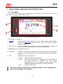
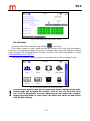
7 FRONT PANEL AND MAIN FUNCTION BUTTONS .............................................. 32
7.1 Front panel ..................................................................................................... 32
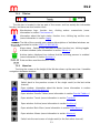
7.1.1 Title bar .................................................................................................... 33
7.1.2 Menu bar ................................................................................................. 33
8 FIRST START UP AND KEY ACTIVITIE ................................................................ 34
8.1 Access control, login and change of user password ...................................... 34
8.1.1 Access control ......................................................................................... 34
8.1.2 Login ........................................................................................................ 34
8.1.3 Changing the password ........................................................................... 35
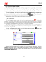
8.2 Change of the language ................................................................................. 35
8.3 Recommended order for configuration of the device ...................................... 35
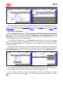
8.4 Reading and saving files using the USB port ................................................. 37
8.5 Factory settings .............................................................................................. 38
9 TECHNICAL SPECIFICATIONS............................................................................. 39
10 ENTITY LAUNCHING THE PRODUCT ON EUROPEAN UNION MARKET .......... 46
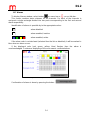
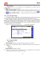
11 USER SCREENS ............................................................................................... 49
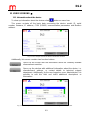
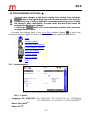
11.1 Information about the device .......................................................................... 49
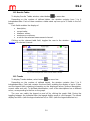
11.2 Results Tables ............................................................................................... 50
11.3 Trends ............................................................................................................ 50
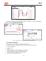
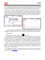
11.4 Single result window ...................................................................................... 51
11.5 Archive ........................................................................................................... 52
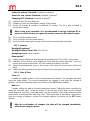
11.6 Main Menu ..................................................................................................... 53
11.7 Alarms ............................................................................................................ 54
12 PROGRAMMING SETTINGS ............................................................................. 55
12.1 General settings ............................................................................................. 55
12.1.1 General .................................................................................................... 55

DL2
5
12.1.2 Display ..................................................................................................... 56
12.1.3 Date & Time ............................................................................................. 56
12.1.4 Service..................................................................................................... 57
12.2 Input and output settings ................................................................................ 57
12.2.1 Module M (MAIN) .................................................................................... 57
12.2.2 Programming options for the individual modules ..................................... 58
12.3 Communication settings ................................................................................. 61
12.3.1 Ethernet port ............................................................................................ 61
12.3.2 RS-485 port ............................................................................................. 61
12.4 Channels settings ........................................................................................... 62
12.4.1 Inputs ....................................................................................................... 62
12.4.2 General .................................................................................................... 63
12.4.3 Alarm ....................................................................................................... 64
12.4.4 Totalizers ................................................................................................. 65
12.5 Screen settings .............................................................................................. 65
12.5.1 Results Tables ......................................................................................... 66
12.5.2 Trends ..................................................................................................... 66
12.6 Archive settings .............................................................................................. 67
13 ARCHIVE ........................................................................................................... 68
13.1 Start, resume and stop archiving .................................................................... 68
13.2 Archive settings .............................................................................................. 68
13.3 Archive files types .......................................................................................... 68
13.4 Way of creating an archive file ....................................................................... 68
13.5 Time interval of archiving data ....................................................................... 68
13.6 Archive files organization ............................................................................... 69
13.6.1 Data archive ............................................................................................ 69
13.6.2 Totalizer archive ...................................................................................... 70
13.6.3 Event archive ........................................................................................... 70
13.7 Copying archive files from the device ............................................................. 71
13.7.1 Copying archive files to USB flash memory ............................................. 71
13.7.2 Copying archive files using device web server ........................................ 71
14 ADDITIONAL FUNCTIONS ................................................................................ 72
14.1 Additional channel functions ........................................................................... 72
14.1.1 Math channels ......................................................................................... 72
14.1.2 User characteristics ................................................................................. 73
14.1.3 Copying channel settings ........................................................................ 74

DL2
6
14.2 Print screen .................................................................................................... 74
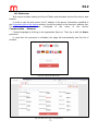
14.3 Web server ..................................................................................................... 75
14.4 Software for PC .............................................................................................. 76
14.4.1 DL2 Config ............................................................................................... 76
14.4.2 DL2-RP .................................................................................................... 77
15 FAILURE SYMBOLS ......................................................................................... 78
16 MODBUS RTU / MODBUS TCP TRANSMISSION PROTOCOL ....................... 79
16.1 General information ........................................................................................ 79
16.1.1 Data types ............................................................................................... 79
16.2 Registers addresses ...................................................................................... 79
16.2.1 Addresses table of Process values .......................................................... 79
16.2.2 Addresses table of Totalizer 1 ................................................................. 80
16.2.3 Addresses table of Totalizer 2 ................................................................. 80
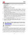
Sections marked with symbol are available only in the CD-ROM version of this
manual attached to the device.

DL2
7
1 SAFETY INFORMATION
Safe operation of this product can only be guaranteed if it is properly installed,
commissioned, used and maintained by qualified personnel in compliance with the
operating instructions. General installation and safety instructions for pipeline and plant
construction, as well as the proper use of tools and safety equipment must also be
complied with.
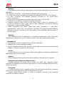
Symbols
Equipment protected throughout by double insulation or reinforced
insulation.
Functional earth (ground) terminal, to enable the product to function
correctly. Not used to provide electrical safety.
Caution, risk of electric shock.
Caution, risk of danger, refer to accompanying documentation.
Caution, Electrostatic Discharge (ESD) sensitive circuit. Do not touch or
handle without proper electrostatic discharge precautions.
!
Important comments and information.
Warning
This product is designed and constructed to withstand the forces encountered during
normal use. Use of the product contrary to its intended purpose or incorrect installation of
the product, any product modifications or repairs incompatible with the following
instructions could:
cause damage to the product / property,
cause injury or fatality to personnel,
void your warranty,
invalidate the marking.
!
Isolate the mains supply before opening the product as hazardous
voltages may be exposed.

DL2
8
Warning
This product complies with the requirements of the following directives and harmonized
standards:
EMC Directive 2014/30/EC to the following standards and specifications:
For EMC immunity for industrial environments according to EN 61326-1:2013 Table 2.
For EMC conductive and radiated emissions according to EN 61326-1:2013
Class A equipment.
The product may be exposed to interference above the limits of EN 61326 if:
The product or its wiring is located near a radio transmitter.
Excessive electrical noise occurs on the mains supply. Power line protectors (AC)
should be installed if mains supply noise is likely. Protectors can combine filtering,
suppression, surge and spike arresters.
Cellular telephones and mobile radios may cause interference if used within
approximately 1 metre (39") of the product or its wiring. The actual separation distance
necessary will vary according to the surroundings of the installation and the power of
the transmitter.
Warning
This device is an Class A equipment. In a residential environment, it may cause radio
interference. In such cases, you can request from its users with appropriate measures.
Intended use
Check that the product is suitable for use with the application.
Determine the correct installation situation.
Prior to installation Metronic AKP products, should take into account any environmental
limitations of devices, specified in the manual.
Access
Ensure safe access and if necessary a safe working platform (suitably guarded) before
attempting to work on the product.
Lighting
Ensure adequate lighting, particularly where detailed or intricate work is required.
Hazardous environment around the product
Consider: explosion risk areas, lack of oxygen (e.g. tanks, pits), dangerous gases,
extremes of temperature, hot surfaces, fire hazard (e.g. during welding), excessive noise,
moving machinery.
The system
Consider the effect on the complete system of the work proposed: will any proposed
action put any other part of the system or any personnel at risk?
Dangers might include isolation of vents or protective devices or the rendering
ineffective of controls or alarms.

DL2
9
Tools and consumables
Before starting work ensure that you have suitable tools and / or consumables
available.
Protective clothing
Consider whether you and / or others in the vicinity require any protective clothing to
protect against the hazards of, for example, chemicals, high / low temperature, radiation,
noise, falling objects, and dangers to eyes and face.
Permits to work
All work must be carried out or be supervised by a suitably competent person.
Installation and operating personnel should be trained in the correct use of the product
according to the Installation and Maintenance Instructions. Where a formal 'permit to work'
system is in force it must be complied with. Where there is no such system, it is
recommended that a responsible person should know what work is going on and, where
necessary, arrange to have an assistant whose primary responsibility is safety.
Post 'warning notices' if necessary.
Cleaning and maintenance
Metronic AKP products require no maintenance beyond periodic battery replacement.
Expected battery life is 10 years after the expiry of which must be returned to the
manufacturer for a replacement.
From time to time you should clean the casing with a dry, soft cloth. When cleaning, do
not use solvents or abrasives. They may cause discoloration or scratch the surfaces of
device.
Disposal
The DL2 contains a battery. On disposal of the unit or component, appropriate
precautions should be taken in accordance with Local / National regulations.
Unless otherwise stated in the Installation and Maintenance Instructions, with the
exception of the battery, this product is recyclable and no ecological hazard is anticipated
with its disposal providing due care is taken.
Returning products
Customers are reminded that under EC Health, Safety and Environment Law, when
returning products to Metronic AKP they must provide information on any hazards and the
precautions to be taken due to contamination residues or mechanical damage which may
present a health, safety or environmental risk. This information must be provided in writing
including Health and Safety data sheets relating to any substances identified as hazardous
or potentially hazardous.

DL2
10
2 DL2 DELIVERY CONTENT, ACCESSORIES AND STORAGE
Prior to dispatch, each Metronic AKP device is inspected and calibrated to
ensure efficient operation.
CAUTION
Upon receipt, each package should be inspected for any potential damage.
The content of the package should also be checked and the actual number of
elements should be compared against the manufacturer's list of items presented in the
consecutive sub-section. In the case of damage or lack of elements, a report should be
drawn up in the presence of the carrier specifying the date of receipt and signature of the
person delivering the package.
2.1 Basic components
The DL2 Data Logger configured to individual customer's order 1 pc.
A set of plug-in type four-pole screw connection 1 set
Fixing clamp 2 pc.
Seal (assembled between case and panel) 1 pc.
A CD with the user instructions and configuration software 1 pc.
Quick start guide - printed 1 pc.
Warranty Card 1 pc.
Certificate of Calibration 1 pc.
2.2 Storage
If the device is to be stored if not used for a period of time and prior to the assembly,
the required storage conditions should be observed. The device should be kept in ambient
temperature range from -30 °C to 70 °C at the relative humidity at 5% to 95% (non-
condensing).
Prior the installation and connecting the device to the power supply make sure that
there is no condensation water inside the device.
2.3 Accessories (optional)
CONV485E
CONV485USB-I
CONV485USB
Power supply unit
USB flash drive

DL2
11
3 GENERAL PRODUCT OVERVIEW
3.1 Purpose
DL2 is a multi-channel microprocessor-based measuring device with electronically
recorded measurement results. The device is intended to measure process signals in
industrial applications and may be used to measure temperature and other physical values
processed into a standard current loop signal 0/4-20mA, e.g. humidity, pressure, flow,
level and chemical composition, etc. The device is perfectly suited for slow rate variable
runs with changes at a few seconds intervals. Process values recording and flexible I/O
configuration, makes the DL2 data logger suitable for monitoring parameters in warehouse
settings or in process lines, where multipoint measurements are required, especially in: the
glass making industry, food processing, refineries, as well as chemical and pharmaceutical
industries. The device has math channels that enable selected mathematical operations
on the measured values, according to the formulas entered by the user. The user
configurable display and browse functions makes the device suitable for use as a paper-
less electronic logger. The device may be connected to a PC or plant control system via
Ethernet or RS-485 communication ports.
Each device is provided with a basic module and can be extended with additional I/O
modules. Details are provided in section DL2 AVAILABLE I/O MODULES.
The device is supplied with 24 VDC source. Detailed information concerning the power
supply is given in consecutive parts of the document, in section Power connection.
3.2 Basic functions
Measurement of the process values
Depending on the needs, the device may be provided with 3 to 12 measurement
inputs/outputs. The product enables setting up to 30 freely programmable channels. For
each of them the current, the maximum and the minimum values of the measurements are
displayed.
Flow measurement
Each measurement input (incl. binary inputs) and each calculated value have two
independent totalizers assigned. Totalizers can measure slow variable flows, etc.
Totalizers for pulse inputs can provide precise pulses count.
Alarms and control
Two alarm thresholds may be set for every channel. Binary outputs can be assigned to
alarm thresholds. Two modes are available for alarms: latched and non-latched. 4 alarm
relays are available as a standard. Next 6 relays may be installed as an I/O module.
Analog output
One 4-20 mA output is available as a standard. Next 3 outputs may be installed as an
I/O module.
Math channels
Within the math channels, selected mathematical operations are available: addition,
subtraction, division, multiplication, raising to the power of 2 and 3, and square root. The
formula entered in the math channel can contain up to 200 characters.

DL2
12
Results recording
Process values, math channels and totalizers can be recorded into internal flash
memory with the capacity of 2 GB. Data are saved as text files and protected with encoded
checksum. Apart from the measured values, the recorder also saves events (power loss,
resetting, exceeded threshold values, etc.) and authorised operations.
Displaying the results
Measured and calculated results can be displayed on the 4” colour LCD screen.
Depending on the configuration, results are displayed as digits or graphs. The results can
be also displayed collectively as tables or trend charts. Measurement screens can be
browsed sequentially or set to a selected channel.
Communication with a computer system
The recorder can be connected to a master computer system by means of:
a built-in RS-485 serial port; Modbus RTU protocol,
Ethernet port; available Modbus TCP protocol.
Software for PC
DL2 - dedicated software (DL2_config.exe) enables device configuration through the
use of the computer. The software enables intuitive use and has an interface which is very
similar to the interface of the device. The software can be installed on the computers with
the MS Win operating system.
The REPORT software (DL2-RP.exe) for archived data enables visualization and
analysis, using the computer. The DL2-RPplus.exe program enables online transfer of
archived data.
3.3 Available options
DL2 is a data recorder created with a view to enabling the best possible adaptation of
the device to the individual needs of the customer. Each device is composed of the base
module to which depending on the metrological needs additional, carefully selected, input
and output modules can be attached. Depending on the needs, the device may have
installed up to two additional modules. Each of them is optionally provided with 3 or 6
measurement channels.
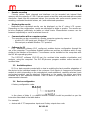
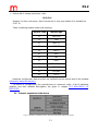
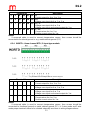
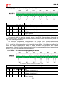
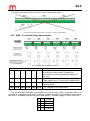
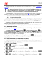
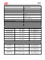
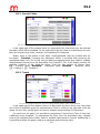
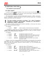
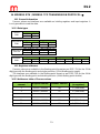
3.4 Device configuration
A factory configuration code:
In the place of letter X, a suitable module number should be provided as per the
instruction described in the table below.
For example:
device with 6 TC temperature inputs and 6 relay outputs has code:
DL2-31-81

DL2
13
device with 6 voltage inputs has code:
DL2-41-0
Number 0 in this code mean, that in the device is only one module (it is installed on
SLOT A).
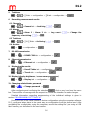
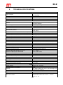
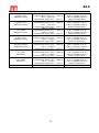
Table containing module codes with marking:
Module code
Module type
11
IN6I(24V)
12
IN6I
21
IN6RTD
22
IN3RTD
31
IN6TC
41
IN6V
51
IN3
61
IN6D
71
IN2RS485(24V)
72
IN2RS485
81
OUT6RL
91
OUT3
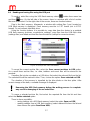
Hardware configuration data may also be verified from the device level in the window
Information about the device.
The device is configured by the manufacturer to customer's order. A list of individual
modules and their detailed descriptions are given in chapter DL2 AVAILABLE I/O
MODULES.
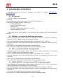
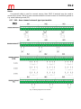
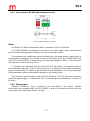
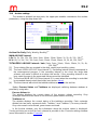
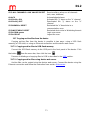
3.5 Galvanic separation in the device
Fig. 3.1 Galvanic separation in DL2 (functional separation 500VAC @ 1min).

DL2
14
4 DL2 AVAILABLE I/O MODULES
Individual electrical connection diagrams are given in section ELECTRICAL
INSTALLATION.
4.1 DL2 base set
Each DL2 device is composed of:
housing,
front panel with touchscreen colour LCD and USB port (type - A),
the basic M module, which is made up of:
4 solid state relays,
one 4-20 mA analog output,
Ethernet port,
RS-485 communication interface connector,
Power supply from 24 VDC.
Depending on the client needs, in the device can be installed up to two input/output
modules.
4.2 IN6I(24V) – six channel 0/4-20mA input type module
standard current loop inputs 0-20mA or 4-20mA for passive or active transducers
(internal 24 VDC voltage source for loop power supply),
linear current measurement within the range or sub-range of -20 .. +20 mA,
galvanic separation from the remaining device circuits, no separation among the input
channels,
each input has a separate four-pole plug-in terminal block,
two colour LED diode informing about the module's operating status.
4.3 IN6I – six channel 0/4-20mA input type module
standard current loop inputs 0-20mA or 4-20mA for active transducers (no internal
24 VDC voltage source for loop power supply),
linear current measurement within the range or sub-range of -20 .. +20 mA,
galvanic separation from the remaining device circuits, no separation among the input
channels,
each input has a separate four-pole plug-in terminal block,
two colour LED diode informing about the module's operating status.
4.4 IN6RTD (IN3RTD) – six (three) channel RTD / R input type module
inputs dedicated for temperature measurements using the Pt, Ni, Cu, KTY type sensors
(see technical data for complete list of sensor types),
linear measurement of the resistance within the range or sub-range 0 .. 4000 Ω,
galvanic separation from the remaining device circuits, no separation among the input
channels,
each input has a separate four-pole plug-in terminal block,
two colour LED diode informing about the module's operating status.

DL2
15
4.5 IN6TC - six channel mV type input module
inputs dedicated for temperature measurements with thermocouples (see technical data
for complete list of sensor types),
compensation of cold junction with a fixed value or a measurement using another
channel,
linear measurement of the voltage within the range or sub-range -140 .. +140 mV,
galvanic separation from the remaining device circuits, no separation among the input
channels,
each input has a separate four-pole plug-in terminal block,
two colour LED diode informing about the module's operating status.
4.6 IN6V – six channel voltage type input module
standard voltage type inputs: 0-10V, 2-10V, 0-5V, and 1-5V,
linear measurement of the voltage within the range or sub-range -10 .. +10 V,
galvanic separation from the remaining device circuits, no separation among the input
channels,
each input has a separate four-pole plug-in terminal block,
two colour LED diode informing about the module's operating status.
4.7 IN3 – three channel universal type input module
software configurable input type:
current loop 0/4-20mA (active transducers),
temperature measurements using the Pt, Ni, Cu, KTY type sensors,
temperature measurements using thermocouples,
voltage type inputs 0 .. 10 V, -10 .. +10 V,
linear current measurement within the range or sub-range of -20 .. +20 mA,
linear measurement of the resistance within the range or sub-range 0 .. 4000 Ω,
linear measurement of the voltage within the range or sub-range -140 .. +140 mV,
-10 .. +10 V,
galvanic separation from the remaining device circuits, no separation among the input
channels,
each input has a separate four-pole plug-in terminal block,
two colour LED diode informing about the module's operating status.
4.8 IN6D – six channel binary inputs module
dedicated to measure frequency, pulse counting or state tracking,
frequency range of 0.1 .. 1000 Hz (pulse counting in range 0 .. 100 Hz),
0 .. 4 VDC / 5.5 .. 34 VDC (3.6 mA) according to EN61131-2 characteristics),
other switching current level at 0.45mA, 1.55mA or 2.44mA can be selected with
jumpers located on the module PCB,
accepts passive pulse transmitter (contact or transistor configuration OC), the source
voltage or current pulses,
galvanic separation from the remaining device circuits, no separation among the input
channels,
each input has a separate three-pole plug-in terminal block,
each input has a LED diode to indicate the input state level,
two colour LED diode informing about the module's operating status.

DL2
16
4.9 IN2RS485 (24V) – two RS485 port input module (Modbus RTU client)
developed to read process values from instruments and sensors over the RS-485 bus
according to the Modbus RTU protocol,
up to 25 digital values can be read by one module, available formats: unsigned or
signed 16 bit or 32 bit integer, signed 64 bit integer, 32 bit or 64 bit floating point,
2 independent and galvanically separated RS485 ports,
each port has a four-pole plug-in terminal block,
extra 24 VDC /max 200 mA voltage source power supply for external transducers,
a two-colour LED diode informing about the module's operating status.
4.10 IN2RS485 – two RS485 port input module (Modbus RTU client)
developed to read process values from instruments and sensors over the RS-485 bus
according to the Modbus RTU protocol,
up to 25 digital values can be read by one module, available formats: unsigned or
signed 16 bit or 32 bit integer, signed 64 bit integer, 32 bit or 64 bit floating point,
2 independent and galvanically separated RS485 ports,
each port has a four-pole plug-in terminal block,
a two-colour LED diode informing about the module's operating status.
4.11 OUT6RL – six channel relay outputs module
galvanically separated from each other 24 VAC or 36 VDC,
0.5 A solid state relays (SSR),
each port has a four-pole plug-in terminal block,
a two-colour LED diode informing about the module's operating status.
4.12 OUT3 – three channel analogue outputs module
Universal type analogue outputs, each can work as a current source or a voltage source
in the following ranges:
0-20 mA (active current loop source),
4-20 mA (active current loop source),
0-24 mA (active current loop source),
0-5 V (voltage source),
0-10 V (voltage source).
12 bits D/A converter resolution,
each channel has two four-pole plug-in terminal blocks, one is for connecting the current
loop receiver, the other one for the voltage receiver (it is not possible to use both current
and voltage source at the same time for the channel),
a two-colour LED diode informing about the module's operating status.
CAUTION
If module IN6I(24V) or IN2RS485(24V) installed and operating as a power supply
source for external devices, ambient temperature is limited to 0° .. +40° C. In all other
configurations the ambient temperature range is 0° .. +50° C.
Detailed technical descriptions of individual modules are given in section
TECHNICAL SPECIFICATIONS.

DL2
17
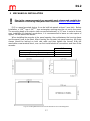
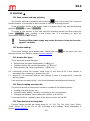
5 MECHANICAL INSTALLATION
!
Prior to the commencement of any assembly work, please read carefully the
information concerning safety described in section SAFETY INFORMATION.
DL2 is a panel-mounted device. It can be built into panels at least 1 mm thick. Before
installation, a 138
(+1)
mm X 68
(+0,7)
mm rectangular opening must be cut out in the panel.
The mounting depth of the device (with connected terminals) is 127 mm. In order to ensure
easy installation of electrical connections, it is recommended to leave an extra space of
approx. 30 mm behind the device.
When installing the recorder in the panel opening, the seal between the housing frame
and the panel have to be fitted. After inserting the recorder into panel opening, the fixing
clamps should be latched on both side walls and then tighten the screws. With the
removable screw terminal block, one can first install electrical connections and then fit the
recorder.
DL2
Mounting cut-out in panel – width
138
(+1)
mm
Mounting cut-out in panel – height
68
(+0,7)
mm
Depth of mounting with connectors
127 mm
Fig. 5.1 Housing dimensions and cut-out dimensions of an assembly panel.

DL2
18
!
The recorder cannot be exposed to direct heat generated by other
equipment.
When assembled, the operating device cannot be affected by interference
from other components (contacts, power relays, inverters).

DL2
19
6 ELECTRICAL INSTALLATION
!
Prior the commencement of any connection works, please read the safety
information given in section SAFETY INFORMATION.
Power supply voltage and all signal wires are connected to plug-in screw terminals,
situated at the back plate of the device. Maximum wires cross-section area is 1.5 mm
2
.
Both wire and cord cables can be used. Wires should be stripped 8 mm to 10 mm at the
end. If cables with a larger cross-section are used, it is recommended to use an
intermediate terminal block in the measurement cabinet between the facility wiring and the
recorder.
DL2 is a modular device. Always M module is installed (see: section DL2 base set).
Depending on the requirements, up to two I/O modules marked A and B are installed (see
detailed information in section DL2 AVAILABLE I/O MODULES).
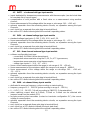
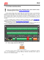
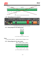
The drawing below shows a rear plate of the base module M and two modules with six
channels. Depending on the device version the rear panel may look different.
Fig. 6.1 Model view of the rear plate of DL2.
6.1 Power supply connection (MODULE M)
Fig. 6.2 Power wiring diagram.
The device requires 24 VDC power supply at minimum 12 W. If supplied from 230/110
VAC, it is recommended to use high efficiency industrial switching power supply at
minimum 15 W of delivered power.

DL2
20
To ensure safety, the recorder's supply must satisfy the conditions
applicable to lower voltage sources SELV (Safety Extra Low-
Voltage), supplied with the 24 VDC as per the IEC60950-1.
In order to eliminate interference, it is recommended to connect the ground wire to the
terminal block (terminal no. 15). It is so called functional ground. This connection is not
required due to safety requirements.
Power consumption depends on the quantity and type of input and output modules. It
should be taken into account that the maximum permissible ambient temperature depends
on device configuration, details are described in section TECHNICAL SPECIFICATION.
6.2 I/O modules – wiring diagrams (SLOT A and B)
Detailed information concerning individual modules is given in section
DL2 AVAILABLE I/O MODULES.
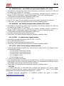
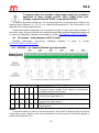
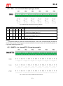
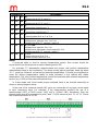
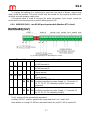
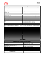
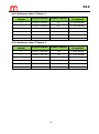
6.2.1 IN6I(24V) – six channel 0/4-20mA input type module
Fig. 6.3 IN6I(24V) module output transducer wiring diagram.
Terminal No
Description
1
5
9
13
17
21
+24V OUT (22 mA max)
Transducer power supply. Each output is protected by
resetable polymer 50 mA fuse.
2
6
10
14
18
22
I+
Current loop signal input (+)
3
7
11
15
19
23
I-
Current loop signal input (-)
4
8
12
16
20
24
GND A
Signal ground
Notes:
If screened cable is used to connect transducer, then GND A terminal may be used to
connect the screen. But it is more recommended to connect screen to functional ground or
metal cabinet ground (PE).
Page is loading ...
Page is loading ...
Page is loading ...
Page is loading ...
Page is loading ...
Page is loading ...
Page is loading ...
Page is loading ...
Page is loading ...
Page is loading ...
Page is loading ...
Page is loading ...
Page is loading ...
Page is loading ...
Page is loading ...
Page is loading ...
Page is loading ...
Page is loading ...
Page is loading ...
Page is loading ...
Page is loading ...
Page is loading ...
Page is loading ...
Page is loading ...
Page is loading ...
Page is loading ...
Page is loading ...
Page is loading ...
Page is loading ...
Page is loading ...
Page is loading ...
Page is loading ...
Page is loading ...
Page is loading ...
Page is loading ...
Page is loading ...
Page is loading ...
Page is loading ...
Page is loading ...
Page is loading ...
Page is loading ...
Page is loading ...
Page is loading ...
Page is loading ...
Page is loading ...
Page is loading ...
Page is loading ...
Page is loading ...
Page is loading ...
Page is loading ...
Page is loading ...
Page is loading ...
Page is loading ...
Page is loading ...
Page is loading ...
Page is loading ...
Page is loading ...
Page is loading ...
Page is loading ...
Page is loading ...
-
 1
1
-
 2
2
-
 3
3
-
 4
4
-
 5
5
-
 6
6
-
 7
7
-
 8
8
-
 9
9
-
 10
10
-
 11
11
-
 12
12
-
 13
13
-
 14
14
-
 15
15
-
 16
16
-
 17
17
-
 18
18
-
 19
19
-
 20
20
-
 21
21
-
 22
22
-
 23
23
-
 24
24
-
 25
25
-
 26
26
-
 27
27
-
 28
28
-
 29
29
-
 30
30
-
 31
31
-
 32
32
-
 33
33
-
 34
34
-
 35
35
-
 36
36
-
 37
37
-
 38
38
-
 39
39
-
 40
40
-
 41
41
-
 42
42
-
 43
43
-
 44
44
-
 45
45
-
 46
46
-
 47
47
-
 48
48
-
 49
49
-
 50
50
-
 51
51
-
 52
52
-
 53
53
-
 54
54
-
 55
55
-
 56
56
-
 57
57
-
 58
58
-
 59
59
-
 60
60
-
 61
61
-
 62
62
-
 63
63
-
 64
64
-
 65
65
-
 66
66
-
 67
67
-
 68
68
-
 69
69
-
 70
70
-
 71
71
-
 72
72
-
 73
73
-
 74
74
-
 75
75
-
 76
76
-
 77
77
-
 78
78
-
 79
79
-
 80
80


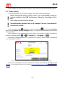
Ask a question and I''ll find the answer in the document
Finding information in a document is now easier with AI
Related papers
Other documents
-
Mitsubishi Electric ME96SSEA-MB User manual
-
Dynisco UPR900 Process Indicator User manual
-
Endres+Hauser ORSG45 Operating instructions
-
TOA V-1068B Specification Data
-
Sierra 240/241 Series Modbus User manual
-
Endres+Hauser BA ORSG35 Operating instructions
-
 Ditel KOS1620 Technical Manual
-
Crowcon GM Addressable Controllers User manual
-
Comet T2218 Quick start guide
-
WIKA T91.10 tag:model:T91.20 Operating instructions
