Page is loading ...


Contents page
1 General Information 1
1.1 At a Glance 1
1.1.1 General remarks 1
1.1.2 Protections for the TEC element 3
1.2 Safety 4
1.3 Ordering codes and Accessories 6
2 Getting Started 7
2.1 Unpacking 7
2.2 Preparation 7
2.3 Preparation 8
2.3.1 Operating elements on front panel 8
2.3.2 Operating elements on rear panel 9
2.4 Starting up 10
3 Operating the TED200 11
3.1 Connecting components 11
3.1.1 Connecting the TEC element 12
3.1.2 Control LED for TEC ON mode 13
3.1.3 Connecting a temperature sensor 13
3.2 Operating the temperature controller 17
3.3 Setting the TEC current limit "ILIM" 18
3.4 Adjusting the temperature control loop 19
3.5 Analog tuning of the temperature 21
3.6 Analog temperature control output 22
3.7 Over-temperature-protection of the TED200 22
4 Maintenance and Repair 23
4.1 Maintenance 23
4.2 Line Voltage Setting 24
4.3 Replacing the mains fuse 26
4.4 Internal Fuse Replacement 27
4.5 Calibrating the temperature sensor 28
4.6 Switching off the I-share of the temperature control loop 29
4.7 Troubleshooting 31
5 Appendix 33
5.1 Warranty 33
5.2 Certifications and compliances 34
5.3 Technical data 36
5.4 Thorlabs “End of Life” policy (WEEE) 38


We aim to develop and produce the best solution for your application in the
field of optical measurement technique. To help us to come up to your
expectations and develop our products permanently we need your ideas and
suggestions. Therefore, please let us know about possible criticism or ideas.
We and our international partners are looking forward to hearing from you.
Thorlabs GmbH
This part of the instruction manual contains specific information on how to operate a
temperature module TED200. A general description is followed by explanations of
how to operate the unit manually.
Attention
This manual contains “WARNINGS” and “ATTENTION” label in this
form, to indicate dangers for persons or possible damage of equip-
ment.
Please read these advises carefully!
NOTE
This manual also contains “NOTES” and “HINTS” written in this form.


1.1 At a Glance
Temperature controller TED200 / page 1
1 General Information
1.1 At a Glance
1.1.1 General remarks
The thermoelectric Temperature Controller TED200 by Thorlabs GmbH is an
extremely precise temperature controller for laser diodes and detectors.
The TED200 is excellently suited for:
• wavelength stabilization of laser diodes
• noise reduction of detectors
• wavelength tuning by regulating the temperature
• modulation of wavelength by tuning the temperature
The unit is easy to use due to the clearly arranged operating elements on the front
panel. The operating parameters are shown by an illuminated 41/2-digit LCD display,
the measurement value shown is selected via keys.
The gain (P-share) the integral share and the differential share of the PID
temperature control loop can be set free and reproducible.
Different temperature sensors can be used with the temperature controller TED200
(thermistor, or temperature IC sensors: AD 590, AD592, LM135, LM 335). With a
thermistor the temperature display is shown as resistance value in kΩ, if the TED200
is operated with a temperature sensor IC the temperature is shown in °C.
The output for the TEC current can be switched on or off via key from the front panel.
The temperature sensor and the TEC element are connected by a 9-pin D-sub plug
at the rear of the unit.
At the output jack a control signal is available to drive an external LED to indicate
TEC ON mode when the TEC current loop is activated.

1.1 At a Glance
Temperature controller TED200 / page 2
The set value of the temperature can be changed with a knob at the front panel or via
an analog input at the rear of the unit.
An analog voltage proportional to the actual value of the temperature is available at
the rear of the unit for monitoring purposes.
The unit has been designed for safe operation with environmental temperatures of
more than 40 °C provided that a free air circulation through the ventilation slots at the
rear and at both sides of the unit is maintained.
In case of overheating caused by too high environmental temperatures or closed
ventilation slots the unit automatically switches the output off to avoid damages.
The LED "OTP" (over-temperature-protection) indicates the over-temperature.
After temperature drop of about 10 °C the LED "OTP" extinguishes and the output
current can be switched on again by pressing the key "ON".
If an error occurs (OTP or OPEN) the corresponding LED lights up and a beeper
gives a short warning signal.
The installed mains filter and the careful shielding of the transformer provide a low
ripple at the output.
If laser diode mounts of the LDH series and the corresponding cables by Thorlabs
GmbH are used damages caused by wrong connections are impossible.

1.1 At a Glance
Temperature controller TED200 / page 3
1.1.2 Protections for the TEC element
To protect the connected TEC element the temperature control system TED200
includes the following protective circuits:
• Limit of the TEC current in all operating modes
Protection against thermal destruction.
• Protection of the sensor
Protection against use of incorrect temperature sensors / protection against line
interruption of the temperature sensor.
• Contact protection of the TEC element (open circuit)
Protection against cable damage, bad contact or TEC element with too high
resistance.
• Control LED for TEC current on
Protection against accidental turning off the cooling.
• Over-temperature protection
Protection against thermal failure of the module.
• Mains filter
Protection against line transients or interference’s.
• Line failure protection
After turning on or in case of power failure or line damage the temperature control
must explicitly be switched on anew since it cannot be taken for granted that all
components of the measurement set-up are still working faultlessly.

1.2 Safety
Temperature controller TED200 / page 4
1.2 Safety
Attention
All statements regarding safety of operation and technical data in
this instruction manual will only apply when the unit is operated
correctly.
Before applying power to your TED200 system make sure that the
protective conductor of the 3 conductor mains power cord is cor-
rectly connected to the protective earth contact of the socket outlet!
Improper grounding can cause electric shock with damages to your
health or even death!
Also make sure that the line voltage setting marked on the rear panel
agrees with your local supply and that the corresponding fuses are
inserted. If not, please have a service technician change the voltage
(see section 4.2).
Changing of the mains fuse can be done by the customer (see
section 4.3).
The unit must only be operated with duly shielded connection cables.
Only with written consent from Thorlabs GmbH may changes to
single components be carried out or components not supplied by
Thorlabs GmbH be used.
This precision device is only dispatchable if duly packed into the
complete original packaging including the plastic form parts. If
necessary, ask for a replacement package.
Attention

1.2 Safety
Temperature controller TED200 / page 5
Mobile telephones, cellular phones or other radio transmitters are
not to be used within the range of three meters of this unit since the
electromagnetic field intensity may then exceed the maximum
allowed disturbance values according to EN 50 082-1.
Attention
The temperature controller TED200 must not be operated in explo-
sion endangered environments!

1.3 Ordering codes and Accessories
Temperature controller TED200 / page 6
1.3 Ordering codes and Accessories
Ordering-code Short description
TED200 thermoelectric Temperature Controller, TEC current 0 ... ± 2 A,
working with thermistors and temperature IC sensors (AD 590, AD
592, LM135 and LM 335) as temperature sensor, illuminated 4½-
digit LCD-display
Shielded cables:
CAB420 cable to connect the Temperature Controller to a Thorlabs GmbH
Laser Diode Mount.

2.1 Unpacking
Temperature controller TED200 / page 7
2 Getting Started
2.1 Unpacking
Inspect the shipping container for damage.
If the shipping container seems to be damaged, keep it until you have inspected the
contents and you have inspected the TED200 mechanically and electrically.
Verify that you have received the following items:
1. 1 TED200
2. 1 power cord, connector according to ordering country
3. 1 operation manual
4. 1 Connection cable CAB 420
2.2 Preparation
Prior to starting operation with a laser diode controller TED200, check if the line
voltage specified on the letter plate agrees with your local supply and if the
appropriate fuse is inserted. (To change the line voltage see 4.2 on page 24)
Connect the unit to the line with the provided mains cable. Turn the unit on by means
of the line switch (L10).
Via the connector jack of the chassis ground (R4) the external optical build-up can be
connected to ground potential, if required. The ground pin of the laser diode is
internally connected to chassis ground.

2.3 Preparation
Temperature controller TED200 / page 8
2.3 Preparation
2.3.1 Operating elements on front panel
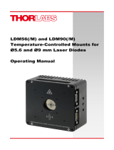
Figure 1 Operating elements on front panel
1 LED for an AD 590, AD 592, LM135 or LM335 sensor
2 LED for a thermistor sensor
3 4½-digit LCD display
4 Temperature display in °C
5 Resistance display in kΩ
6 Current display in A
7 LED for TEC element not or wrong connected"
8 LED "over-temperature-protection"
9 LED "TEC output switched on"
10 On/off switch for temperature control loop
11 Setting the set temperature "TSET"
12 Mains power control switch (ON / OFF)
13 Setting the current limit "ILIM" for the TEC element
14 LED to display the actual temperature "TACT´"
15 LED to display the TEC current "ITEC"
16 LED to display the set temperature "TSET"
17 LED to display the current limit "ILIM"
18 Selecting the measurement value for display (toggle switch down)
19 Selecting the measurement value for display (toggle switch up)
20 Setting the gain of the control loop (P-share)
21 Setting the I-share of the control loop
22 Setting the D-share of the control loop
I
12 13 14 15 1617 18 19 20 21 22
O
1234567891011

2.3 Preparation
Temperature controller TED200 / page 9
2.3.2 Operating elements on rear panel
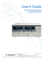
Figure 2 Operating elements on rear panel
R1 Analog control input "TUNE IN"
R2 Analog control output "CTL OUT"
R3 Fan
R4 Chassis ground
R5 9-pin D-sub jack for the TEC element and the temperature sensor
R6 Selecting the temperature sensor and the thermistor resistance range
R7 Serial number of the unit
R8 Letterplate for line voltage
R9 Mains socket and fuse holder

2.4 Starting up
Temperature controller TED200 / page 10
2.4 Starting up
Prior to starting operation with the thermoelectric Temperature Controller TED200,
check if the line voltage specified on the letter plate agrees with your local supply and
if the appropriate fuse is inserted. If not see chapter 4.2 to set the appropriate line
voltage. Connect the unit to the line with the provided mains cable.
Turn on the unit using the mains power control switch at the front panel.
The LC-display (3, Figure 1) must get visible and a LED must light to indicate the
selected measurement value (14 to 17).
With the keys (18) and (19) you can select the desired measurement value at any
time.
Independent of the switch position (R6) the setting and measurement range with
thermistors is between 0 and 19.99 kΩ or 0 and 199.9 kΩ respectively. When the AD
590, AD 592, LM135 or LM335 is used as a temperature sensor the measurement
range is between -45 °C and + 145 °C. The actual control range depends on the
sensor ratings and the individual thermal setup.
The unit TED200 is immediately ready to use after turning on. The rated accuracy is
however reached after a warming-up time of approx. 10 minutes.

3.1 Connecting components
Temperature controller TED200 / page 11
3 Operating the TED200
3.1 Connecting components
Connecting TEC element and temperature sensor
If Laser Diode Heads (LDH) by Thorlabs GmbH are used, the output "TE OUTPUT"
(R5) of the Temperature Controller TED200 must be connected to the 9-pin plug
"TEC DRIVER" of the LDH with a shielded cable CAB420.
With other equipment connect the TEC element and the temperature sensor
according to Figure 3.
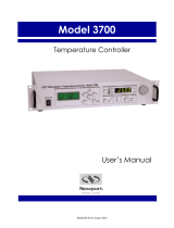
Figure 3 Output pinning of the 9-pole D-SUB jack (male)
Pin Connection
TEC element, status indication:
4 TEC (+)
5 TEC (-), status-LED (-)
1 Status-LED (+) (for TEC ON/OFF indication)
Temperature sensor:
2 Thermistor (-)
3 Thermistor (+), ground
7 Transducer AD 590/592 (-), LM 135/335 (+)
9 Transducer AD 590/592 (+), LM135/335 (+)
6 N.C.
8 AGND LM 135/335
1-2-3-4-
5
6-7-8-9

3.1 Connecting components
Temperature controller TED200 / page 12
3.1.1 Connecting the TEC element
Connect the thermoelectric cooler between pin 4 (TEC anode) and pin 5 (TEC
cathode) of the 9-pin D-sub plug (R5, see Figure 2).
Attention
An reverse poled TEC element may lead to thermal runaway and
destruction of the connected components.
Check the TEC polarity as follows:
Turn on the Temperature Controller TED200
Connect the temperature sensor to the plug "TE OUTPUT" (R5)
(refer to 3.1.3, "Connecting a temperature sensor" on page 13).
Select a suitable current limit "ILIM" for the TEC element
(refer to 3.3, Setting the TEC current limit "ILIM" on page 18).
Switch the LCD display to the measurement range "TSET" and set the desired set
temperature with the tuning knob.
By pressing the key "ON" switch on the TED200 output current. The LED "ON" (9,
see Figure 1) lights up.
Switch the LCD display to the measurement range "TACT".
If the TEC module is connected with right polarity, the difference between the set
temperature "TSET" and the actual temperature "TACT" will decrease. If the control
loop parameters are set well (refer to chapter 3.4), the actual temperature must be in
accordance with the set temperature in a short time.
If the TEC module is connected with wrong polarity, the difference between set
temperature and actual temperature will increase continuously. Then switch off the
TEC current by pressing key "ON" (9) and change the TEC module wiring at the D-
sub plug (R5).

3.1 Connecting components
Temperature controller TED200 / page 13
3.1.2 Control LED for TEC ON mode
If a LED is connected between pin 1 and pin 5 as shown in Figure 4 this LED lights
up when the TEC current output is switched on (TEC ON mode).
Figure 4 TEC ON monitoring
3.1.3 Connecting a temperature sensor
The Temperature Controller TED200 can be used with a standard thermistor, with an
AD 590, AD 592, LM 135 or an LM 335 as temperature sensor. The temperature
sensor is selected with switch (R6) at the rear of the unit (see Figure 2).
The LED's (1) or (2) resp. indicate the selected sensor.
If no temperature sensor is connected or if the temperature sensor does not
correspond to the sensor type selected with switch (R6) the LCD display (3) indicates
overflow when "TACT" measurement value is shown and the LED "OPEN" (7) lights
up in TEC OFF mode.
The temperature sensor is connected to the 9-pin D-sub plug "TE OUTPUT" (R5) at
the rear of the TED200 depending on the sensor type used.
NOTE
Additionally to the AD 590 or AD592 temperature sensor the TED200 also
works with an LM 335 sensor. If an LM 335 is used as temperature sensor
also select "AD 590" with the switch (R6). Thus also the LED "AD 590" (1)
lights up. The LM 335 sensor must be connected according to
Figure 7.

3.1 Connecting components
Temperature controller TED200 / page 14
3.1.3.1 Connecting a thermistor
The thermistor must be connected between pin 2 and pin 3 of the 9-pin D-sub plug
(R5, Figure 2). The polarity is unimportant if the thermistor is floating. If one pin of the
thermistor is grounded (for example in a laser module), this pin has to be connected
to pin 3.
If the Temperature Controller TED200 is operated with a thermistor as temperature
sensor the thermistor resistance at set temperature "TSET" must be set in kΩ.
Figure 5 Connecting a thermistor
When the actual temperature "TACT" is chosen for display the thermistor resistance is
shown. The switch (R6, Figure 2) selects the resistance range of the thermistor. In
position "L" (Low) the maximum thermistor range is 20 kΩ and the measurement
current 100 µA. In position "H" (High) the maximum thermistor resistance is 200 kΩ
and the measurement current 10 µA.
The dependency of resistance on temperature and vice versa of an NTC-thermistor
is described by the formula:
val
val
TT
B
B
R
R
T
TB
RTeRTR val
+
=⇔∗=
−
)ln(*
*
)()(
0
0
0
)
11
(
00
(temperatures in Kelvin)
with: R0: Thermistor nominal resistance at temperature T0
T
0: Nominal temperature (typ. 298.15 K = 25°C)
B
val: Energy constant
2
3
/