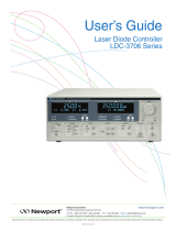
ILX Lightwave LDC-3700C Series User manual

Type
User manual
User’s Guide
Laser Diode Controller
LDC-3700C Series
70041001 April 2009
ILX Lightwave Corporation · 31950 Frontage Road · Bozeman, MT, U.S.A. 59715 · U.S. & Canada: 1-800-459-9459 · International Inquiries: 406-556-2481 · Fax 406-586-9405
ilx.custhelp.com · www.ilxlightwave.com
TABLE OF CONTENTS
04_09 LDC-3700C Series i

TABLE OF CONTENTS
Safety Information and the Manual . . . . . . . . . . . . . . . . . . . . . . . . . . . . . . . . . ix
General Safety Considerations . . . . . . . . . . . . . . . . . . . . . . . . . . . . . . . . . . . . ix
Safety Marking Symbols . . . . . . . . . . . . . . . . . . . . . . . . . . . . . . . . . . . . . . . . . x
Limitations . . . . . . . . . . . . . . . . . . . . . . . . . . . . . . . . . . . . . . . . . . . . . . . . . . xi
Returning an Instrument . . . . . . . . . . . . . . . . . . . . . . . . . . . . . . . . . . . . . . . xi
Claims for Shipping Damage . . . . . . . . . . . . . . . . . . . . . . . . . . . . . . . . . . . .xii
Comments, Suggestions, and Problems . . . . . . . . . . . . . . . . . . . . . . . . . . . xiii
Chapter 1 Introduction and Specifications
Product Overview . . . . . . . . . . . . . . . . . . . . . . . . . . . . . . . . . . . . . . . . . . . . . . . . 1
Initial Inspection . . . . . . . . . . . . . . . . . . . . . . . . . . . . . . . . . . . . . . . . . . . . . . . 1
Installing the LDC-3700C . . . . . . . . . . . . . . . . . . . . . . . . . . . . . . . . . . . . . . . . . . 2
Grounding Requirements . . . . . . . . . . . . . . . . . . . . . . . . . . . . . . . . . . . . . . . 2
AC Line Power Requirements . . . . . . . . . . . . . . . . . . . . . . . . . . . . . . . . . . . 2
USB . . . . . . . . . . . . . . . . . . . . . . . . . . . . . . . . . . . . . . . . . . . . . . . . . . . . . . . 2
GPIB Connector . . . . . . . . . . . . . . . . . . . . . . . . . . . . . . . . . . . . . . . . . . . . . . 3
The GPIB Address . . . . . . . . . . . . . . . . . . . . . . . . . . . . . . . . . . . . . . . . . . . . 3
Tilt-Foot Adjustment . . . . . . . . . . . . . . . . . . . . . . . . . . . . . . . . . . . . . . . . . . . 3
Rack Mounting . . . . . . . . . . . . . . . . . . . . . . . . . . . . . . . . . . . . . . . . . . . . . . . 3
Operating the LDC-3700C Laser Diode Controller . . . . . . . . . . . . . . . . . . . . . 3
How to Obtain Repair Services . . . . . . . . . . . . . . . . . . . . . . . . . . . . . . . . . . . . 5
Laser Current Source Specifications1 . . . . . . . . . . . . . . . . . . . . . . . . . . . . . . . . 6
Temperature Controller Specifications1 . . . . . . . . . . . . . . . . . . . . . . . . . . . . . . 8
General LDC-3700C Specifications . . . . . . . . . . . . . . . . . . . . . . . . . . . . . . . . . . 9
Available Options and Accessories . . . . . . . . . . . . . . . . . . . . . . . . . . . . . . 11
TABLE OF CONTENTS
ii LDC-3700C Series
Chapter 2 Operations
Applying Power to your LD Controller . . . . . . . . . . . . . . . . . . . . . . . . . . . . . . 13
The Power On Sequence . . . . . . . . . . . . . . . . . . . . . . . . . . . . . . . . . . . . . 13
The Power On State . . . . . . . . . . . . . . . . . . . . . . . . . . . . . . . . . . . . . . . . . . . 14
37x4C Series Default Configuration: . . . . . . . . . . . . . . . . . . . . . . . . . . . . . 14
Connecting to the Laser Controller . . . . . . . . . . . . . . . . . . . . . . . . . . . . . . . . . 15
Connecting the Laser Current Source . . . . . . . . . . . . . . . . . . . . . . . . . . . . 17
Interlock Connections . . . . . . . . . . . . . . . . . . . . . . . . . . . . . . . . . . . . . . . . 17
Photodiode Connections . . . . . . . . . . . . . . . . . . . . . . . . . . . . . . . . . . . . . . 17
Setting the PD bias . . . . . . . . . . . . . . . . . . . . . . . . . . . . . . . . . . . . . . . . . . 18
Grounding Considerations . . . . . . . . . . . . . . . . . . . . . . . . . . . . . . . . . . . . . 18
Connecting to the TE Controller . . . . . . . . . . . . . . . . . . . . . . . . . . . . . . . . . . . 19
TEC Grounding Considerations . . . . . . . . . . . . . . . . . . . . . . . . . . . . . . . . . 19
Operating from the Front Panel . . . . . . . . . . . . . . . . . . . . . . . . . . . . . . . . . . . . 20
The Laser Controller Display . . . . . . . . . . . . . . . . . . . . . . . . . . . . . . . . . . . 20
Operating a Laser in Constant Current “I” Mode . . . . . . . . . . . . . . . . . . . . . 20
Set Up the Controller . . . . . . . . . . . . . . . . . . . . . . . . . . . . . . . . . . . . . . . . . 20
Set the Range . . . . . . . . . . . . . . . . . . . . . . . . . . . . . . . . . . . . . . . . . . . . . . 21
Select the Laser Display . . . . . . . . . . . . . . . . . . . . . . . . . . . . . . . . . . . . . . 21
Adjusting the Set Point . . . . . . . . . . . . . . . . . . . . . . . . . . . . . . . . . . . . . . . 21
Set Current Source Limit . . . . . . . . . . . . . . . . . . . . . . . . . . . . . . . . . . . . . . 22
Set Compliance Voltage Limit . . . . . . . . . . . . . . . . . . . . . . . . . . . . . . . . . . 23
Automatic Shutoff Conditions for Laser Output . . . . . . . . . . . . . . . . . . . . . 24
Operating a Laser in Constant Power Mode, P . . . . . . . . . . . . . . . . . . . . . . 24
Entering Photodiode Responsivity values . . . . . . . . . . . . . . . . . . . . . . . . . 24
LASER Error Indicators . . . . . . . . . . . . . . . . . . . . . . . . . . . . . . . . . . . . . . . 28
Operating the TE Controller from the Front Panel . . . . . . . . . . . . . . . . . . . . . 29
The TEC display . . . . . . . . . . . . . . . . . . . . . . . . . . . . . . . . . . . . . . . . . . . . 29
Operating the Controller in Temperature Mode, T . . . . . . . . . . . . . . . . . . . . 29
Setting up the Temperature Controller . . . . . . . . . . . . . . . . . . . . . . . . . . . 29
Temperature Controller Sensor Selection . . . . . . . . . . . . . . . . . . . . . . . . . 30
Setting Temperature Sensor Constants . . . . . . . . . . . . . . . . . . . . . . . . . . 31
Setting TE Control Loop Gain . . . . . . . . . . . . . . . . . . . . . . . . . . . . . . . . . . 32
Setting Temperature Controller Limits . . . . . . . . . . . . . . . . . . . . . . . . . . . . 33
Adjusting the Temperature Set Point . . . . . . . . . . . . . . . . . . . . . . . . . . . . . 34
Operating the Controller in Resistance (Sensor) Mode, R . . . . . . . . . . . . 35
Operating the Controller in Constant Current Mode, ITE . . . . . . . . . . . . . . . . . . .35
Automatic Shut Off Conditions for TEC Output . . . . . . . . . . . . . . . . . . . . . 35
TEC Error Indicators . . . . . . . . . . . . . . . . . . . . . . . . . . . . . . . . . . . . . . . . . 36
Functions and Features . . . . . . . . . . . . . . . . . . . . . . . . . . . . . . . . . . . . . . . . . . 37
TABLE OF CONTENTS
04_09 LDC-3700C Series iii
Saving and Recalling from the Front Panel . . . . . . . . . . . . . . . . . . . . . . . . . 37
Using the Laser Compliance Voltage Adjustment . . . . . . . . . . . . . . . . . . . . 38
Using the LDC-3700C Controller’s Trigger Function . . . . . . . . . . . . . . . . . . 38
Modulating the Controller Laser Current Source . . . . . . . . . . . . . . . . . . . . . 39
Boosting the TE Controller . . . . . . . . . . . . . . . . . . . . . . . . . . . . . . . . . . . . . . 41
Chapter 3 Remote Operation
USB Operations . . . . . . . . . . . . . . . . . . . . . . . . . . . . . . . . . . . . . . . . . . . . . . . . . 43
USB Driver Installation . . . . . . . . . . . . . . . . . . . . . . . . . . . . . . . . . . . . . . . . . 43
Basic GPIB Concepts . . . . . . . . . . . . . . . . . . . . . . . . . . . . . . . . . . . . . . . . . . . . 44
Data and Interface Messages . . . . . . . . . . . . . . . . . . . . . . . . . . . . . . . . . . . . 44
Talkers, Listeners, and Controllers . . . . . . . . . . . . . . . . . . . . . . . . . . . . . . 44
GPIB Cable Connections . . . . . . . . . . . . . . . . . . . . . . . . . . . . . . . . . . . . . . 45
The GPIB Connector . . . . . . . . . . . . . . . . . . . . . . . . . . . . . . . . . . . . . . . . . 45
Reading the GPIB Address . . . . . . . . . . . . . . . . . . . . . . . . . . . . . . . . . . . . 46
Changing the GPIB Address . . . . . . . . . . . . . . . . . . . . . . . . . . . . . . . . . . . 46
Changing Operation from Local to Remote . . . . . . . . . . . . . . . . . . . . . . . . . . 47
Command Syntax . . . . . . . . . . . . . . . . . . . . . . . . . . . . . . . . . . . . . . . . . . . . . . . 48
Letters . . . . . . . . . . . . . . . . . . . . . . . . . . . . . . . . . . . . . . . . . . . . . . . . . . . . 48
White Space . . . . . . . . . . . . . . . . . . . . . . . . . . . . . . . . . . . . . . . . . . . . . . . 48
Terminators . . . . . . . . . . . . . . . . . . . . . . . . . . . . . . . . . . . . . . . . . . . . . . . . 49
Command Separators . . . . . . . . . . . . . . . . . . . . . . . . . . . . . . . . . . . . . . . . 49
Parameters . . . . . . . . . . . . . . . . . . . . . . . . . . . . . . . . . . . . . . . . . . . . . . . . 49
Command Tree Structure . . . . . . . . . . . . . . . . . . . . . . . . . . . . . . . . . . . . . 50
Syntax Summary . . . . . . . . . . . . . . . . . . . . . . . . . . . . . . . . . . . . . . . . . . . . 51
IEEE488.2 Common Commands . . . . . . . . . . . . . . . . . . . . . . . . . . . . . . . . . 53
LDC-3700C Commonly Used Commands . . . . . . . . . . . . . . . . . . . . . . . . . . 54
Status Reporting . . . . . . . . . . . . . . . . . . . . . . . . . . . . . . . . . . . . . . . . . . . . . . 55
Event and Condition Registers . . . . . . . . . . . . . . . . . . . . . . . . . . . . . . . . . 55
Operation Complete Definition . . . . . . . . . . . . . . . . . . . . . . . . . . . . . . . . . . 56
Output Off Registers . . . . . . . . . . . . . . . . . . . . . . . . . . . . . . . . . . . . . . . . . 58
Command Timing . . . . . . . . . . . . . . . . . . . . . . . . . . . . . . . . . . . . . . . . . . . . . 61
Sequential/Overlapped Commands . . . . . . . . . . . . . . . . . . . . . . . . . . . . . . 61
Query Response Timing . . . . . . . . . . . . . . . . . . . . . . . . . . . . . . . . . . . . . . 61
TABLE OF CONTENTS
iv LDC-3700C Series
Chapter 4 Command Reference
Remote Command Reference Summary . . . . . . . . . . . . . . . . . . . . . . . . . . . . . 64
Command Reference . . . . . . . . . . . . . . . . . . . . . . . . . . . . . . . . . . . . . . . . . . . . 69
Chapter 5 Calibration and Troubleshooting
Calibration Overview . . . . . . . . . . . . . . . . . . . . . . . . . . . . . . . . . . . . . . . . . . . . 135
Recommended Equipment . . . . . . . . . . . . . . . . . . . . . . . . . . . . . . . . . . . . . 136
Local Calibration of the LDC-3700C Temperature Controller . . . . . . . . . 139
Calibrating the Thermistor . . . . . . . . . . . . . . . . . . . . . . . . . . . . . . . . . . . . 139
AD590 Sensor Calibration . . . . . . . . . . . . . . . . . . . . . . . . . . . . . . . . . . . . 140
LM335 Sensor Calibration . . . . . . . . . . . . . . . . . . . . . . . . . . . . . . . . . . . . 140
ITE Current Calibration . . . . . . . . . . . . . . . . . . . . . . . . . . . . . . . . . . . . . . 141
Local Calibration of the Laser Current Source . . . . . . . . . . . . . . . . . . . . . 142
Current Source Calibration . . . . . . . . . . . . . . . . . . . . . . . . . . . . . . . . . . . . . 142
IPD Current Calibration . . . . . . . . . . . . . . . . . . . . . . . . . . . . . . . . . . . . . . . 144
Laser Forward Voltage Measurement Calibration . . . . . . . . . . . . . . . . . . 146
Remote Calibration of the LDC-3700C Controller . . . . . . . . . . . . . . . . . . . 147
Thermistor Calibration . . . . . . . . . . . . . . . . . . . . . . . . . . . . . . . . . . . . . . . 147
AD590 Sensor Calibration . . . . . . . . . . . . . . . . . . . . . . . . . . . . . . . . . . . . 148
LM335 Sensor Calibration . . . . . . . . . . . . . . . . . . . . . . . . . . . . . . . . . . . . 148
ITE Current Calibration . . . . . . . . . . . . . . . . . . . . . . . . . . . . . . . . . . . . . . . 149
TEC Voltage Calibration . . . . . . . . . . . . . . . . . . . . . . . . . . . . . . . . . . . . . . . 150
Current Source Calibration . . . . . . . . . . . . . . . . . . . . . . . . . . . . . . . . . . . 151
IPD Current Calibration . . . . . . . . . . . . . . . . . . . . . . . . . . . . . . . . . . . . . . . 153
Laser Forward Voltage Measurement Calibration . . . . . . . . . . . . . . . . . . 154
Troubleshooting . . . . . . . . . . . . . . . . . . . . . . . . . . . . . . . . . . . . . . . . . . . . . . . 155
Error Messages . . . . . . . . . . . . . . . . . . . . . . . . . . . . . . . . . . . . . . . . . . . . . 157
LIST OF FIGURES
04_09 LDC-3700C Series v

LIST OF FIGURES
Figure 1.1 LDC 3700C Series Controller Front View . . . . . . . . . . . . .4
Figure 1.2 LDC-3700C Rear Panel . . . . . . . . . . . . . . . . . . . . . . . . . .4
Figure 2.1 Laser Diode Connection Configurations . . . . . . . . . . . . .16
Figure 2.2 Back Panel LD Connector . . . . . . . . . . . . . . . . . . . . . . . .17
Figure 2.3 Rear Panel TEC Connector . . . . . . . . . . . . . . . . . . . . . . .19
Figure 2.4 LDC-3700C Series Rear Panel . . . . . . . . . . . . . . . . . . . .39
Figure 2.5 Rear Panel TEC Connector . . . . . . . . . . . . . . . . . . . . . . .41
Figure 3.1 GPIB Cable Connections . . . . . . . . . . . . . . . . . . . . . . . .45
Figure 3.2 GPIB Connector Diagram . . . . . . . . . . . . . . . . . . . . . . . .46
Figure 3.3 Command Path Structure . . . . . . . . . . . . . . . . . . . . . . . .51
Figure 3.4 Common Command Diagrams . . . . . . . . . . . . . . . . . . . .53
Figure 3.5 Status Reporting Scheme . . . . . . . . . . . . . . . . . . . . . . . .57
Figure 3.6 LASER Output Off Register . . . . . . . . . . . . . . . . . . . . . . .59
Figure 3.7 TEC Output Off Register . . . . . . . . . . . . . . . . . . . . . . . . .59
Figure 5.1 IPD Calibration Circuit . . . . . . . . . . . . . . . . . . . . . . . . . . .137
LIST OF FIGURES
vi LDC-3700C Series
LIST OF TABLES
04_09 LDC-3700C Series vii

LIST OF TABLES
Table 1.1 Options and Accessories . . . . . . . . . . . . . . . . . . . . . . . . . .11
Table 2.1 Laser Error Indicators. . . . . . . . . . . . . . . . . . . . . . . . . . . . .28
Table 2.2 SENSOR SELECT Switch Positions . . . . . . . . . . . . . . . . .31
Table 2.3 TEC Error Indicators . . . . . . . . . . . . . . . . . . . . . . . . . . . . .36
Table 3.1 Substitute Parameter Names . . . . . . . . . . . . . . . . . . . . . .50
Table 3.2 Invalid Syntax Command Strings. . . . . . . . . . . . . . . . . . . .52
Table 3.3 LDC-3700C Commonly Used Commands. . . . . . . . . . . . .54
Table 3.4 Default Settings for Output Off Registers. . . . . . . . . . . . . .58
Table 4.1 Remote Command Summary Reference List. . . . . . . . . . .64
Table 5.1 Recommended Test Equipment. . . . . . . . . . . . . . . . . . . .136
Table 5.2 Required Calibration Components. . . . . . . . . . . . . . . . . .138
Table 5.3 Symptoms and Actions . . . . . . . . . . . . . . . . . . . . . . . . . .155
Table 5.4 Error Code Classifications . . . . . . . . . . . . . . . . . . . . . . . .157
Table 5.5 Error Messages . . . . . . . . . . . . . . . . . . . . . . . . . . . . . . . .157
LIST OF TABLES
viii LDC-3700C Series
LDC-3700C Series ix
S
AFETY
AND
W
ARRANTY
I
NFORMATION
The Safety and Warranty Information section provides details about cautionary
symbols used in the manual, safety markings used on the instrument, and
information about the Warranty including Customer Service contact information.
Safety Information and the Manual
Throughout this manual, you will see the words Caution and Warning indicating
potentially dangerous or hazardous situations which, if not avoided, could result in
death, serious or minor injury, or damage to the product. Specifically:
!
CAUTION
Caution indicates a potentially hazardous situation which can result in minor or
moderate injury or damage to the product or equipment.
WARNING
Warning indicates a potentially dangerous situation which can result in serious injury or
death.
WARNING
Visible and/or invisible laser radiation. Avoid direct exposure to the beam.
General Safety Considerations
If any of the following conditions exist, or are even suspected, do not use the
instrument until safe operation can be verified by trained service personnel:
Visible damage
Severe transport stress
Prolonged storage under adverse conditions
Failure to perform intended measurements or functions
If necessary, return the instrument to ILX Lightwave, or authorized local ILX
Lightwave distributor, for service or repair to ensure that safety features are
maintained (see the contact information on page xiii).
SAFETY SYMBOLS
x LDC-3700C Series
All instruments returned to ILX Lightwave are required to have a Return
Authorization Number assigned by an official representative of ILX Lightwave
Corporation. See Returning an Instrument on page xi for more information.
S
AFETY
S
YMBOLS
This section describes the safety symbols and classifications.
Technical specifications including electrical ratings and weight are included within
the manual. See the Table of Contents to locate the specifications and other
product information. The following classifications are standard across all ILX
Lightwave products:
Indoor use only
Ordinary Protection: This product is NOT protected against the harmful ingress of moisture.
Class I Equipment (grounded type)
Mains supply voltage fluctuations are not to exceed ±10% of the nominal supply voltage.
Pollution Degree II
Installation (overvoltage) Category II for transient overvoltages
Maximum Relative Humidity: <80% RH, non-condensing
Operating temperature range of 0°C to 40°C
Storage and transportation temperature of -40°C – 70°C
Maximum altitude: 3000 m (9843 ft)
This equipment is suitable for continuous operation.
Safety Marking Symbols
This section provides a description of the safety marking symbols that appear on
the instrument. These symbols provide information about potentially dangerous
situations which can result in death, injury, or damage to the instrument and other
components.
WARRANTY
LDC-3700C Series xi
W
ARRANTY
ILX LIGHTWAVE CORPORATION warrants this instrument to be free from
defects in material and workmanship for a period of one year from date of
shipment. During the warranty period, ILX will repair or replace the unit, at our
option, without charge.
Limitations
This warranty does not apply to fuses, lamps, defects caused by abuse,
modifications, or to use of the product for which it was not intended.
This warranty is in lieu of all other warranties, expressed or implied, including any
implied warranty of merchantability or fitness for any particular purpose. ILX
Lightwave Corporation shall not be liable for any incidental, special, or
consequential damages.
If a problem occurs, please contact ILX Lightwave Corporation with the
instrument's serial number, and thoroughly describe the nature of the problem.
Returning an Instrument
If an instrument is to be shipped to ILX Lightwave for repair or service, be sure to:
1Obtain a Return Authorization number (RA) from ILX Customer Service.
2Attach a tag to the instrument identifying the owner and indicating the required service or
repair. Include the instrument serial number from the rear panel of the instrument.
Caution,
refer to
manual
Earth
ground
Te r m i n a l
Alternating
current
Visible and/or
invisible laser
radiation
Caution, risk
of electric
shock
Protective
Conductor
Te r m i n a l
Caution, hot
surface
Frame or
chassis
Te r m i n a l
On: In position of a bistable push control.
The slash (I) only denotes that mains are on.
Off: Out position of a bistable push control.
The circle (O) only denotes that mains are off.
or
(I)
or
(O)
WARRANTY
xii LDC-3700C Series
3Attach the anti-static protective caps that were shipped with the instrument and place the
instrument in a protective anti-static bag.
4Place the instrument in the original packing container with at least 3 inches (7. 5 cm) of
compressible packaging material. Shipping damage is not covered by this warranty.
5Secure the packing box with fiber reinforced strapping tape or metal bands.
6Send the instrument, transportation pre-paid, to ILX Lightwave. Clearly write the return
authorization number on the outside of the box and on the shipping paperwork. ILX
Lightwave recommends you insure the shipment.
If the original shipping container is not available, place your instrument in a
container with at least 3 inches (7.5 cm) of compressible packaging material on all
sides.
Repairs are made and the instrument returned transportation pre-paid. Repairs
are warranted for the remainder of the original warranty or for 90 days, whichever
is greater.
Claims for Shipping Damage
When you receive the instrument, inspect it immediately for any damage or
shortages on the packing list. If the instrument is damaged, file a claim with the
carrier. The factory will supply you with a quotation for estimated costs of repair.
You must negotiate and settle with the carrier for the amount of damage.
WARRANTY
LDC-3700C Series xiii
Comments, Suggestions, and Problems
To ensure that you get the most out of your ILX Lightwave product, we ask that
you direct any product operation or service related questions or comments to ILX
Lightwave Customer Support. You may contact us in whatever way is most
convenient:
Phone . . . . . . . . . . . . . . . . . . . . . . . . . . . (800) 459-9459 or (406) 586-1244
Fax . . . . . . . . . . . . . . . . . . . . . . . . . . . . . . . . . . . . . . . . . . . . . (406) 586-9405
Email. . . . . . . . . . . . . . . . . . . . . . . . . . . . . . . . . . . .[email protected]
Or mail to:
ILX Lightwave Corporation
P. O. Box 6310
Bozeman, Montana, U.S.A 59771
www.ilxlightwave.com
When you contact us, please have the following information:
If ILX Lightwave determines that a return to the factory is necessary, you are
issued a Return Authorization (RA) number. Please mark this number on the
outside of the shipping box.
You or your shipping service are responsible for any shipping damage when
returning the instrument to ILX Lightwave; ILX recommends you insure the
shipment. If the original shipping container is not available, place your instrument
Model Number:
Serial Number:
End-user Name:
Company:
Phone:
Fax:
Description or sketch of what
is connected to the ILX
Lightwave instrument:
Description of the problem:
WARRANTY
xiv LDC-3700C Series
in a container with at least 3 inches (7.5cm) of compressible packaging material
on all sides.
We look forward to serving you even better in the future!
LDC-3700C Series 1
CHAPTER 1

INTRODUCTION AND SPECIFICATIONS
This chapter is an introduction to the LDC-3700C Series Laser Diode Controllers
and contains unpacking information, instructions on how to install and apply
power, maintenance information, specifications, and listings of the LDC-3700C
options and accessories.
Product Overview
The LDC-3700C Series Laser Diode Controllers are a combination current
source/temperature controller. The current source provides a high stability output
with a fully redundant current limit and multiple laser protection features. The
built-in temperature controller can work with most temperature sensors and TE
modules to deliver precise laser temperature control over a wide range of
temperatures. The LDC-3700C Series' fast, sophisticated USB or GPIB
communications lets you automate your experiment.
Initial Inspection
When you receive your LDC-3700C Controller, verify that the following items were
shipped with the instrument:
LDC-3700C Laser Diode Controller
LDC-3700C Series Manual
Power Cord
Shipping Kit
INTRODUCTION AND SPECIFICATIONS
Installing the LDC-3700C
2 LDC-3700C Series
CHAPTER 1
Installing the LDC-3700C
This section provides information about the necessary requirements to install the
LDC-3700C and how to begin operating the instrument.
Grounding Requirements
The LDC-3700C Laser Diode Controller comes with a three conductor AC power
cable. The power cable must be plugged into an approved three-contact electrical
outlet or used with a three-contact to two-contact adapter with the grounding wire
connected to an electrical ground (safety ground). The LDC-3700C supplied
power cable meets all applicable national safety standards.
AC Line Power Requirements
You can operate the LDC-3700C Series Controllers from a single phase power
source delivering nominal line voltages of 100, 120, 220, 230-240 VAC (all values
RMS) from 50 to 60 Hz. The line power voltage can vary ±10%. Maximum power
consumption is 360 VA (Volt-Amps). The instrument's operational voltage is
configured at the factory and cannot be changed. However, check to make sure
the voltage printed on the back panel of the instrument matches the power-line
voltage in your area.
Before connecting the LDC-3700C Laser Diode Controller to a power source, verify that
the AC power source matches the setting of the LDC-3700C's voltage printed on the rear
panel of the instrument.
To avoid electrical shock hazard, connect the instrument to properly earth-grounded
electrical receptacles only. Failure to observe this precaution can result in severe injury
or death.
USB
The USB connector is located on the back rear panel, directly below the GPIB
connector. This USB connector is the square "B"-style connector. A standard USB
A/B cable is required to communicate with the instrument. To communicate to the
instrument using USB, please install the Virtual Com Port Driver found on the
accompanying CD or website prior to connecting the unit to the PC. Please refer
to Chapter 3 for more detailed instructions on operating the instrument through
USB.
INTRODUCTION AND SPECIFICATIONS
Installing the LDC-3700C
04_09 LDC-3700C Series 3
CHAPTER 1
GPIB Connector
The IEEE 488.2 GPIB interface connector is located on the rear panel, directly
above the power input module and fuse (See Figure 1.2 on page 4). Attach the
GPIB cable to the 24-pin connector located on the rear panel. The connector is
tapered to ensure proper orientation. Finger tighten the two screws on the cable
connector.
A total of 15 devices can be connected together on the same GPIB interface bus.
The cables have single male/female connectors on each end so that several
cables can be stacked. This allows more than one cable to be attached to any
one device. However, the maximum length of the GPIB cables must not exceed
20 meters (65 feet) total, or 2 meters (6.5 feet) per device.
The GPIB Address
The talk and listen addresses on the LDC-3700C Series Laser Diode Controller
are identical. This GPIB address is read locally by pressing the GPIB LOCAL
switch with the address displayed on the "TEC" display. The controller comes
from the factory configured with the GPIB address set to 1. You can change the
LDC-3700C's GPIB address locally (via front panel). A procedure for changing
the address can be found in the section Changing the GPIB Address on page 46.
Tilt-Foot Adjustment
The LDC-3700C Series Laser Diode Controller comes standard with folding front
legs and two rear feet for use as a bench top instrument. Extending the front feet
so that the instrument front panel sits up makes it easier to view the LED displays.
To use them, place the unit on a stable base and rotate the front legs downward
until they lock into position.
Rack Mounting
The LDC-3700C Series Laser Diode Controller can be mounted in a standard
19-inch rack with the optional rack mount kits. The kits contain a rack mount
flange and hardware for mounting on either side of the enclosure. All rack mount
accessory kits contain detailed mounting instructions.
Operating the LDC-3700C Laser Diode Controller
Now that the LDC-3700C Laser Diode Controller is installed and ready for use,
you can begin to learn about its operation. The following figures are front and rear
photographic copies showing the functional keypad groupings, rear panel
connectors, and so on. Use these figures to familiarize yourself with the
LDC-3700C Controller. After that, use Chapter 2 for fundamentals of operating
the controller.
INTRODUCTION AND SPECIFICATIONS
Installing the LDC-3700C
4 LDC-3700C Series
CHAPTER 1
Figure 1.1 LDC 3700C Series Controller Front View
Figure 1.2 LDC-3700C Rear Panel
Potentially lethal voltages exist within the LDC-3700C Series Laser Diode Controller. To
avoid electric shock, do not perform any maintenance on the instrument. Qualified
service personnel are required to wear protective eyeglasses and anti-static wrist bands
while working on the LDC-3700C Series Laser Diode Controller circuit boards. High
voltages are present on and around the controller's printed circuit boards.
There are no user serviceable parts in the instrument, including the external fuses in the
AC power entry module. Contact ILX Customer Service for information about servicing
the instrument.
  • Page 1 1
  • Page 2 2
  • Page 3 3
  • Page 4 4
  • Page 5 5
  • Page 6 6
  • Page 7 7
  • Page 8 8
  • Page 9 9
  • Page 10 10
  • Page 11 11
  • Page 12 12
  • Page 13 13
  • Page 14 14
  • Page 15 15
  • Page 16 16
  • Page 17 17
  • Page 18 18
  • Page 19 19
  • Page 20 20
  • Page 21 21
  • Page 22 22
  • Page 23 23
  • Page 24 24
  • Page 25 25
  • Page 26 26
  • Page 27 27
  • Page 28 28
  • Page 29 29
  • Page 30 30
  • Page 31 31
  • Page 32 32
  • Page 33 33
  • Page 34 34
  • Page 35 35
  • Page 36 36
  • Page 37 37
  • Page 38 38
  • Page 39 39
  • Page 40 40
  • Page 41 41
  • Page 42 42
  • Page 43 43
  • Page 44 44
  • Page 45 45
  • Page 46 46
  • Page 47 47
  • Page 48 48
  • Page 49 49
  • Page 50 50
  • Page 51 51
  • Page 52 52
  • Page 53 53
  • Page 54 54
  • Page 55 55
  • Page 56 56
  • Page 57 57
  • Page 58 58
  • Page 59 59
  • Page 60 60
  • Page 61 61
  • Page 62 62
  • Page 63 63
  • Page 64 64
  • Page 65 65
  • Page 66 66
  • Page 67 67
  • Page 68 68
  • Page 69 69
  • Page 70 70
  • Page 71 71
  • Page 72 72
  • Page 73 73
  • Page 74 74
  • Page 75 75
  • Page 76 76
  • Page 77 77
  • Page 78 78
  • Page 79 79
  • Page 80 80
  • Page 81 81
  • Page 82 82
  • Page 83 83
  • Page 84 84
  • Page 85 85
  • Page 86 86
  • Page 87 87
  • Page 88 88
  • Page 89 89
  • Page 90 90
  • Page 91 91
  • Page 92 92
  • Page 93 93
  • Page 94 94
  • Page 95 95
  • Page 96 96
  • Page 97 97
  • Page 98 98
  • Page 99 99
  • Page 100 100
  • Page 101 101
  • Page 102 102
  • Page 103 103
  • Page 104 104
  • Page 105 105
  • Page 106 106
  • Page 107 107
  • Page 108 108
  • Page 109 109
  • Page 110 110
  • Page 111 111
  • Page 112 112
  • Page 113 113
  • Page 114 114
  • Page 115 115
  • Page 116 116
  • Page 117 117
  • Page 118 118
  • Page 119 119
  • Page 120 120
  • Page 121 121
  • Page 122 122
  • Page 123 123
  • Page 124 124
  • Page 125 125
  • Page 126 126
  • Page 127 127
  • Page 128 128
  • Page 129 129
  • Page 130 130
  • Page 131 131
  • Page 132 132
  • Page 133 133
  • Page 134 134
  • Page 135 135
  • Page 136 136
  • Page 137 137
  • Page 138 138
  • Page 139 139
  • Page 140 140
  • Page 141 141
  • Page 142 142
  • Page 143 143
  • Page 144 144
  • Page 145 145
  • Page 146 146
  • Page 147 147
  • Page 148 148
  • Page 149 149
  • Page 150 150
  • Page 151 151
  • Page 152 152
  • Page 153 153
  • Page 154 154
  • Page 155 155
  • Page 156 156
  • Page 157 157
  • Page 158 158
  • Page 159 159
  • Page 160 160
  • Page 161 161
  • Page 162 162
  • Page 163 163
  • Page 164 164
  • Page 165 165
  • Page 166 166
  • Page 167 167
  • Page 168 168
  • Page 169 169
  • Page 170 170
  • Page 171 171
  • Page 172 172
  • Page 173 173
  • Page 174 174
  • Page 175 175
  • Page 176 176

ILX Lightwave LDC-3700C Series User manual

Type
User manual

Ask a question and I''ll find the answer in the document

Finding information in a document is now easier with AI