Page is loading ...

90026356 RevG August 2016
Temperature Controller
User’s Manual
Model 3700

ii Preface
EU Declaration of Conformity
We declare that the accompanying product, identified with the mark,
complies with requirements of the Electromagnetic Compatibility Directive,
2004/108/EC and the Low Voltage Directive 2006/95/EC.
Model Number: 3700
Year mark affixed: 2009
Type of Equipment: Electrical equipment for measurement, control and
laboratory use in industrial locations.
Manufacturer: Newport Corporation
1791 Deere Avenue
Irvine, CA 92606
Standards Applied:
Compliance was demonstrated to the following standards to the extent
applicable:
BS EN61326-1: 2006 “Electrical equipment for measurement, control and
laboratory use – EMC requirements”.
BS EN 61010-1:2010 “Safety requirements for electrical equipment for
measurement, control and laboratory use”.
Todd McFarland
Senior Electrical Engineer
31950 E Frontage Rd
Bozeman, MT, USA

Preface iii iii
Warranty
Newport Corporation warrants that this product will be free from defects in
material and workmanship and will comply with Newport’s published
specifications at the time of sale for a period of one year from date of
shipment. If found to be defective during the warranty period, the product
will either be repaired or replaced at Newport's option.
To exercise this warranty, write or call a local Newport office or
representative, or contact Newport headquarters in Irvine, California. Prompt
assistance and return instructions will be given. Send the product, freight
prepaid, to the indicated service facility. Repairs will be made and the
instrument returned freight prepaid. Repaired products are warranted for the
remainder of the original warranty period or 90 days, whichever first occurs.
Limitation of Warranty
The above warranties do not apply to products which have been repaired or
modified without Newport’s written approval, or products subjected to
unusual physical, thermal or electrical stress, improper installation, misuse,
abuse, accident or negligence in use, storage, transportation or handling. This
warranty also does not apply to fuses, batteries, or damage from battery
leakage.
THIS WARRANTY IS IN LIEU OF ALL OTHER WARRANTIES,
EXPRESSED OR IMPLIED, INCLUDING ANY IMPLIED WARRANTY
OF MERCHANTABILITY OR FITNESS FOR A PARTICULAR USE.
NEWPORT CORPORATION SHALL NOT BE LIABLE FOR ANY
INDIRECT, SPECIAL, OR CONSEQUENTIAL DAMAGES RESULTING
FROM THE PURCHASE OR USE OF ITS PRODUCTS.
First printing 2013
© 2013 by Newport Corporation, Irvine, CA. All rights reserved. No part of
this manual may be reproduced or copied without the prior written approval
of Newport Corporation.
This manual has been provided for information only and product
specifications are subject to change without notice. Any change will be
reflected in future printings.
Newport Corporation
1791 Deere Avenue
Irvine, CA, 92606
USA
Part No. 90026356 August 2016

iv Preface
Confidentiality & Proprietary Rights
Reservation of Title:
The Newport programs and all materials furnished or produced in connection
with them ("Related Materials") contain trade secrets of Newport and are for
use only in the manner expressly permitted. Newport claims and reserves all
rights and benefits afforded under law in the Programs provided by Newport
Corporation.
Newport shall retain full ownership of Intellectual Property Rights in and to
all development, process, align or assembly technologies developed and other
derivative work that may be developed by Newport. Customer shall not
challenge, or cause any third party to challenge the rights of Newport.
Preservation of Secrecy and Confidentiality and Restrictions to Access:
Customer shall protect the Newport Programs and Related Materials as trade
secrets of Newport, and shall devote its best efforts to ensure that all its
personnel protect the Newport Programs as trade secrets of Newport
Corporation. Customer shall not at any time disclose Newport's trade secrets
to any other person, firm, organization, or employee that does not need
(consistent with Customer's right of use hereunder) to obtain access to the
Newport Programs and Related Materials. These restrictions shall not apply
to information (1) generally known to the public or obtainable from public
sources; (2) readily apparent from the keyboard operations, visual display, or
output reports of the Programs; 3) previously in the possession of Customer
or subsequently developed or acquired without reliance on the Newport
Programs; or (4) approved by Newport for release without restriction.
Trademarks
The Newport logo is a registered trademark of Newport Corporation in
Austria, Barbados, Benelux, Canada, the People’s Republic of China,
Denmark, France, Germany, Great Britain, Ireland, Japan, the Republic of
Korea, Spain, Sweden, and the United States. Newport is a registered
trademark of Newport Corporation in Austria, Barbados, Benelux, the
People’s Republic of China, Denmark, France, Germany, Ireland, Japan, the
Republic of Korea, Spain, and Sweden.
Service Information
This section contains information regarding factory service for the source.
The user should not attempt any maintenance or service of the system or
optional equipment beyond the procedures outlined in this manual. Any
problem that cannot be resolved should be referred to Newport Corporation.

Preface v v
Technical Support Contacts
North America & Asia
Europe
Newport Corporation Service Dept.
1791 Deere Ave. Irvine, CA 92606
Telephone: (949) 253-1694
Telephone: (800) 222-6440 x31694
Newport/MICRO-CONTROLE S.A.
Zone Industrielle
45340 Beaune la Rolande, FRANCE
Telephone: (33) 02 38 40 51 56
Asia
Newport Opto-Electronics
Technologies
中国 上海市 爱都路 253号 第3号楼 3层
C部位, 邮编 200131
253 Aidu Road, Bld #3, Flr 3, Sec C,
Shanghai 200131, China
Telephone: +86-21-5046 2300
Fax: +86-21-5046 2323
Newport Corporation Calling Procedure
If there are any defects in material or workmanship or a failure to meet
specifications, promptly notify Newport's Returns Department by calling 1-800-222-
6440 or by visiting our website at www.newport.com/returns within the warranty
period to obtain a Return Material Authorization Number (RMA#). Return the
product to Newport Corporation, freight prepaid, clearly marked with the RMA# and
the product will either be repaired or replaced it at our discretion. Newport is not
responsible for damage occurring in transit and is not obligated to accept products
returned without an RMA#.
E-mail: rma.serv[email protected]
When calling Newport Corporation, please provide the customer care representative
with the following information:
Your Contact Information
Serial number or original order number
Description of problem (i.e., hardware or software)
To help our Technical Support Representatives diagnose the problem, please note
the following conditions:
Is the system used for manufacturing or research and development?
What was the state of the system right before the problem?
Has this problem occurred before? If so, how often?
Can the system continue to operate with this problem? Or is the system non-
operational?
Is there anything that was different before this problem occurred?

vi Preface
This page is intentionally left blank

Preface vii vii
Table of Contents
EU Declaration of Conformity ............................................................... ii
Warranty ................................................................................................ iii
Technical Support Contacts ................................................................... v
Table of Contents ................................................................................. vii
List of Figures and Tables ...................................................................... x
1 Safety Precautions 11
1.1 Definitions and Symbols ............................................................ 11
1.1.1 General Warning or Caution ...........................................11
1.1.2 Electric Shock ..................................................................11
1.1.3 European Union CE Mark ...............................................12
1.1.4 Alternating voltage symbol .............................................12
1.1.5 On ....................................................................................12
1.1.6 Off ....................................................................................12
1.1.7 Fuses ................................................................................13
1.1.8 USB .................................................................................13
1.1.9 Frame or Chassis .............................................................13
1.1.10 Waste Electrical and Electronic Equipment (WEEE) .....13
1.1.11 Control of Hazardous Substances ....................................14
1.2 Warnings and Cautions ............................................................... 14
1.2.1 General Warnings ..........................................................155
1.2.2 General Cautions .............................................................15
1.2.3 Summary of Warnings and Cautions ...............................16
1.3 Location of Labels and Warnings ............................................... 17
1.3.1 Rear Panel ........................................................................17
2 General Information 19
2.1 Introduction ................................................................................ 19
2.1.1 High-Power Temperature Controller for TE Cooling
Needs ...............................................................................19
2.2 Available Options and Accessories ............................................ 20
2.3 Specifications ............................................................................. 21
3 Getting Started 25
3.1 Unpacking and Handling ............................................................ 25
3.2 Inspection for Damage ............................................................... 25
3.3 Parts List ..................................................................................... 26

viii Preface
3.4 Choosing and Preparing a Suitable Work Surface ..................... 26
3.5 Electrical Requirements .............................................................. 26
3.6 Power Supplies ........................................................................... 27
4 System Operation 29
4.1 General Features ......................................................................... 29
4.2 TEC Safety Features ................................................................... 29
4.2.1 Conditions Which Will Automatically Shut Off the TEC
Output ..............................................................................29
4.3 Front Panel .................................................................................. 30
4.3.1 Power ON / OFF Switch ..................................................30
4.3.2 OUTPUT ON Switch and Indicator ................................30
4.3.3 ERROR Indicator LED ....................................................31
4.3.4 LIMIT Indicator LED ......................................................31
4.3.5 MODE Switch .................................................................32
4.3.6 DISPLAY Section ...........................................................33
4.3.7 Control Knob ...................................................................34
4.4 Menu Section .............................................................................. 34
4.4.1 Setup / Enter ....................................................................34
4.4.2 Esc ...................................................................................34
4.4.3 Cursor Arrow Keys ..........................................................34
4.4.4 Display Elements .............................................................35
4.5 Rear Panel ................................................................................... 45
4.5.1 USB Interface ..................................................................45
4.5.2 Chassis GND ...................................................................45
4.5.3 AC Power Cord ...............................................................45
4.5.4 Fuses ................................................................................45
4.5.5 TEC Output Connector ....................................................46
4.5.6 I/O Signals Connector .....................................................47
4.6 I/O Signals .................................................................................. 48
4.6.1 ON / OFF Output .............................................................48
4.6.2 Fault .................................................................................49
4.6.3 TTL Input ........................................................................49
4.6.4 TTL Output ......................................................................49
4.6.5 Auxiliary Thermistor Input / Auxiliary Thermistor Input
(Return) ............................................................................49
4.6.6 Analog Output / Analog Output (Return) .......................50
4.6.7 Chassis Ground ................................................................50

Preface ix ix
5 Computer Interfacing 51
5.1 General Guidelines ..................................................................... 51
5.2 Computer Interface Terminology ............................................... 51
5.2.1 <…> Delimiting Punctuation ..........................................51
5.2.2 <CR> Carriage Return .....................................................51
5.2.3 <LF> Line Feed ...............................................................51
5.2.4 (;) Semicolons ..................................................................51
5.2.5 Command Termination ....................................................52
5.2.6 Response Termination .....................................................52
5.3 Controller Operation Mode ........................................................ 52
5.4 USB Communication .................................................................. 52
5.5 Commands and Queries .............................................................. 53
6 Principles of Operation 83
6.1 Introduction ................................................................................ 83
6.2 TEC Handling Precautions ......................................................... 83
6.3 TEC Controller Operation .......................................................... 85
6.3.1 Thermistor and Thermistor Current Selection .................85
6.3.2 AD590 and LM335 ..........................................................89
6.3.3 RTD Sensors ....................................................................93
7 Tips and Techniques 95
7.1 Introduction ................................................................................ 95
7.2 TEC Limits ................................................................................. 95
7.2.1 Current Limit ...................................................................95
7.2.2 Voltage Limit ...................................................................95
7.2.3 Operating at or Near Io and Vte Limits ...........................95
7.3 Grounding a TEC ....................................................................... 96
8 Maintenance and Service 97
8.1 Enclosure Cleaning ..................................................................... 97
8.2 Obtaining Service ....................................................................... 97
8.3 Service Form .............................................................................. 98
9 Appendix A – Error Messages 99
9.1 Introduction ................................................................................ 99
9.2 Error Description ........................................................................ 99

x Preface
List of Figures
Figure 1 General Warning or Caution Symbol .......................................... 11
Figure 2 Electrical Shock Symbol ............................................................... 11
Figure 3 CE Mark ......................................................................................... 12
Figure 4 Alternating Voltage Symbol ......................................................... 12
Figure 5 On Symbol ...................................................................................... 12
Figure 6 Off Symbol ..................................................................................... 12
Figure 7 Fuse Symbol ................................................................................... 13
Figure 8 USB Symbol ................................................................................... 13
Figure 9 Frame or Chassis Terminal Symbol ............................................ 13
Figure 10 WEEE Directive Symbol ............................................................... 13
Figure 11 RoHS Compliant Symbol .............................................................. 14
Figure 12 Rear Panel Labels and Warnings ................................................ 17
Figure 13 Front Panel Layout ........................................................................ 30
Figure 14 A Sample Title Screen ................................................................... 35
Figure 15 A Sample Measurement Screen ................................................... 35
Figure 16 A Sample Setup Screen ................................................................. 36
Figure 17 Model 3700 Menu Structure ......................................................... 37
Figure 18 A Sample Set Limits Sub-menu .................................................... 39
Figure 19 A Sample Set PID Gains Sub-menu ............................................. 40
Figure 20 A Sample Customize PID Gains Sub-menu ................................ 40
Figure 21 A Sample Sensor Constants Sub-menu ....................................... 41
Figure 22 A Sample System Parameters Sub-menu .................................... 42
Figure 23 A Sample Save Parameters Sub-menu ........................................ 43
Figure 24 A Sample Recall Parameters Sub-menu ...................................... 43
Figure 25 A Sample Measurement Screen when Errors Present ............... 44
Figure 26 A Sample Setup Screen when Errors Present ............................. 44
Figure 27 Rear Panel ...................................................................................... 45
Figure 28 Thermistor Temperature Range .................................................. 86
Figure 29 Thermistor Resistance verus Temperature ................................. 88
Figure 30 AD590 Nonlinearity .......................... Error! Bookmark not defined.0
List of Tables
Table 1 Error and Limit LED Status Definition ...................................... 31
Table 2 Setpoint Display ............................................................................. 33
Table 3 R/Temp Display ............................................................................. 34
Table 4 Setpoint Labels ............................................................................... 39
Table 5 TEC Connector Pin-out (Viewed looking at Rear Panel ........... 46
Table 6 I/O Signals Connector Pin Assignments ...................................... 47
Table 7 Command Summary ................................................................... 554
Table 8 HWCONFIG Register ................................................................... 60
Table 9 Analog Output Mode Register ..................................................... 61
Table 10 Thermistor Constants ...................... 8Error! Bookmark not defined.
Table 11 RTD Constants .................................... Error! Bookmark not defined.

90026356 RevG August 2016
1 Safety Precautions
1.1 Definitions and Symbols
The following terms and symbols are used in this documentation and also
appear on the Model 3700 Temperature Controller where safety-related
issues occur.
1.1.1 General Warning or Caution
General Warning or Caution Symbol Figure 1
The Exclamation Symbol in the figure above appears on the product and in
Warning and Caution tables throughout this document. This symbol
designates that documentation needs to be consulted to determine the nature
of a potential hazard, and any actions that have to be taken.
1.1.2 Electric Shock
Electrical Shock Symbol Figure 2
The Electrical Shock Symbol in the figure above appears throughout this
manual. This symbol indicates a hazard arising from dangerous voltage.
Any mishandling could result in irreparable damage to the equipment, and
personal injury or death.

12 Safety Precautions
1.1.3 European Union CE Mark
CE Mark Figure 3
The presence of the CE Mark on Newport Corporation equipment means that
this instrument has been designed, tested and certified as complying with all
applicable European Union (CE) regulations and recommendations.
1.1.4 Alternating voltage symbol
Alternating Voltage Symbol Figure 4
This international symbol implies an alternating voltage or current.
1.1.5 On
I
On Symbol
Figure 5
The symbol in the figure above represents a power switch position on the
Model 3700 Temperature Controller. This symbol represents a Power On
condition.
1.1.6 Off
Off Symbol Figure 6
The symbol in the figure above represents a power switch position on the
Model 3700 Temperature Controller. This symbol represents a Power Off
condition.
~

Safety Precautions 13 13
1.1.7 Fuses
Fuse Symbol Figure 7
The symbol in the figure above identifies the fuse location on the Model 3700
Temperature Controller.
1.1.8 USB
USB Symbol Figure 8
The symbol in the figure above identifies the USB connector location on the
Model 3700 Temperature Controller.
1.1.9 Frame or Chassis
Frame or Chassis Terminal Symbol Figure 9
The symbol in the figure above appears on the Model 3700 Temperature
Controller. This symbol identifies the frame or chassis terminal
1.1.10 Waste Electrical and Electronic Equipment (WEEE)
WEEE Directive Symbol Figure 10
This symbol on the product or on its packaging indicates that this product
must not be disposed of with regular waste. Instead, it is the user
responsibility to dispose of waste equipment according to the local laws. The
separate collection and recycling of the waste equipment at the time of

14 Safety Precautions
disposal will help to conserve natural resources and ensure that it is recycled
in a manner that protects human health and the environment. For information
about where the user can drop off the waste equipment for recycling, please
contact a local Newport Corporation representative.
1.1.11 Control of Hazardous Substances
RoHS Compliant Symbol Figure 11
This label indicates the products comply with the EU Directive 2002/95/EC
that restricts the content of six hazardous chemicals.
1.2 Warnings and Cautions
The following are definitions of the Warnings, Cautions and Notes that are
used throughout this manual to call attention to important information
regarding personal safety, the safety and preservation of the equipment or an
important tip.
WARNING
Situation has the potential to cause bodily harm or death.
CAUTION
Situation has the potential to cause damage to property or
equipment.
NOTE
Additional information the user or operator should consider.

Safety Precautions 15 15
1.2.1 General Warnings
Observe these general warnings when operating or servicing this equipment:
Heed all warnings on the unit and in the operating instructions.
Do not use this equipment in or near water.
This equipment is grounded through the grounding conductor of the
power cord.
Route power cords and other cables so that they are not likely to be
damaged.
Disconnect power before cleaning the equipment. Do not use liquid or
aerosol cleaners; use only a damp lint-free cloth.
Lockout all electrical power sources before servicing the equipment.
To avoid fire hazard, use only the specified fuse(s) with the correct type
number, voltage and current ratings as referenced in the appropriate
locations in the service instructions or on the equipment. Only qualified
service personnel should replace fuses.
To avoid explosion, do not operate this equipment in an explosive
atmosphere.
Qualified service personnel should perform safety checks after any
service.
1.2.2 General Cautions
Observe these cautions when operating this equipment:
If this equipment is used in a manner not specified in this manual, the
protection provided by this equipment may be impaired.
To prevent damage to equipment when replacing fuses, locate and correct
the problem that caused the fuse to blow before re-applying power.
Do not block ventilation openings.
Do not position this product in such a manner that would make it difficult
to disconnect the power cord.
Position the equipment so that access to the mains disconnect On/Off
switch is readily available.
Use only the specified replacement parts.
Follow precautions for static sensitive devices when handling this
equipment.
This product should only be powered as described in the manual.
There are no user-serviceable parts inside the Model 3700 Temperature
Controller.
Adhere to good laser safety practices when using this equipment.

16 Safety Precautions
1.2.3 Summary of Warnings and Cautions
The following general warning and cautions are applicable to this instrument:
WARNING
Before operating the Model 3700 Temperature Controller, please
read and understand all of Section 1.
WARNING
Do not attempt to operate this equipment if there is evidence of
shipping damage or suspect the unit is damaged. Damaged
equipment may present additional personal hazards. Contact
Newport technical support for advice before attempting to plug
in and operate damaged equipment.
WARNING
To avoid electric shock, connect the instrument to properly
earth-grounded, 3-prong receptacles only. Failure to observe
this precaution can result in severe injury.
WARNING
Before cleaning the enclosure of the Model 3700 Temperature
Controller, disconnect the AC power cord must be disconnected
from the wall socket.
CAUTION
There are no user serviceable parts inside the Model 3700
Temperature Controller. Work performed by persons not
authorized by Newport Corporation will void the warranty. For
instructions on obtaining warranty repair or service, please refer
to Section 8.
The Model 3700 is intended for use in an industrial environment.
Use of this product in other environments, such as residential,
may result in electromagnetic compatibility difficulties due to
conducted as well as radiated disturbances.

Safety Precautions 17 17
1.3 Location of Labels and Warnings
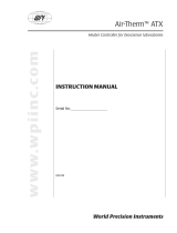
1.3.1 Rear Panel
Rear Panel Labels and Warnings Figure 12
CE Label
MAX Power
Model, Serial
Number and
WEEE symbol
Fuse Label
RoHS Label
Chassis Ground

18 Safety Precautions
This page is intentionally left blank

90026356 RevG August 2016
2 General Information
2.1 Introduction
Model 3700 Temperature Controller is a result of Newport’s continuing
commitment to deliver innovative solutions that enable its customers’
success. It offers reliable, high output power at a very competitive price.
The ergonomic layout and intuitive front panel controls make this versatile
instrument extremely easy to use. A wide range of TEC temperature control
and user safety features were thoroughly analyzed and designed into this
instrument which complies with CE standards.
Key Product Features:
USB Plug-and-Play Interface
Temperature Controller
336 Watt output power
Ultra stable bipolar output
Support for thermistors, AD590, LM335, and Pt RTD sensors.
2.1.1 High-Power Temperature Controller for TE Cooling Needs
The 300 Watt Temperature Controller is designed to meet the most
demanding thermoelectric (TE) cooling needs. It can be operated in one of
the following three modes:
Constant Temperature
Constant Resistance / Reference
Constant TE Current
Short-term stability is better than 0.001°C, while long-term stability is better
than 0.002°C. Four sensor types are compatible with this TEC:
Thermistors
AD590 series

20 General Information
LM335 series
100Ω Platinum RTDs
With the sensor’s calibration constants, the actual temperature is displayed in
°C on the front panel.
Intuitive Controls and LCD Display
Improved data presentation and system control are achieved using a
combination of LCD and 7-segment LED displays. The LCD display shows
the entire system configuration as well as TEC status and the LED display
provides high readability and quick temperature setting capability. “Menu
Keys” guide the user through initial system setup routines and operation.
Real-time control of an output is accomplished either by entering the set
point via the cursor keys or control knob. SETUP/ENTER and ARROW
keys access saved system configurations and repetitive procedures. All
controls are clearly marked and instructions easily understood for simple
operation.
Support for Remote Data Collection
All control and measurement functions are accessible via the USB interface.
As the user’s instrumentation needs change, the Model 3700 Temperature
Controller will adapt the user’s new applications giving the ultimate in
flexible laboratory equipment.
2.2 Available Options and Accessories
3150-02 Temperature Controller Cable
3150-04 Temperature Controller/Mount Cable
Newport Corporation also supplies temperature controlled mounts and other
accessories. Please consult with a representative for additional information.
/