Page is loading ...

User’s Guide
32 Watt Temperature Control Module
TCM-39032
ILX Lightwave Corporation P. O. Box 6310 Bozeman, MT, U.S.A.59771 :· · · 1-800-459-9459 · ·
www.ilxlightwave.com
U.S.& Canada International Inquiries: 406-586-1244 Fax 406-586-9405
E-mail: support@ilxlightwave.com
70011703_R00_06/03


TABLE OF CONTENTS
4_03 TCM-39032 i
TABLE OF CONTENTS
Safety Information and the Manual . . . . . . . . . . . . . . . . . . . . . . . . . . . . . . . . . iii
General Safety Considerations . . . . . . . . . . . . . . . . . . . . . . . . . . . . . . . . . . . . iii
Safety Marking Symbols . . . . . . . . . . . . . . . . . . . . . . . . . . . . . . . . . . . . . . . . . iv
Comments, Suggestions, and Problems . . . . . . . . . . . . . . . . . . . . . . . . . . . .vii
Chapter 1 Introduction and Specifications
Product Overview . . . . . . . . . . . . . . . . . . . . . . . . . . . . . . . . . . . . . . . . . . . . . . . . 1
Specifications
1
. . . . . . . . . . . . . . . . . . . . . . . . . . . . . . . . . . . . . . . . . . . . . . . . . . . 2
Installation . . . . . . . . . . . . . . . . . . . . . . . . . . . . . . . . . . . . . . . . . . . . . . . . . . . . . . 4
Chapter 2 Operation
SENSOR SELECT Switches . . . . . . . . . . . . . . . . . . . . . . . . . . . . . . . . . . . . . . . . 6
TEC Connector . . . . . . . . . . . . . . . . . . . . . . . . . . . . . . . . . . . . . . . . . . . . . . . . . . 7
TEC Grounding Considerations . . . . . . . . . . . . . . . . . . . . . . . . . . . . . . . . . . . . . 7
TEC Interlock . . . . . . . . . . . . . . . . . . . . . . . . . . . . . . . . . . . . . . . . . . . . . . . . . . . . 7
Booster Operation . . . . . . . . . . . . . . . . . . . . . . . . . . . . . . . . . . . . . . . . . . . . . . . . 8
Chapter 3 Calibration
Recommended Equipment . . . . . . . . . . . . . . . . . . . . . . . . . . . . . . . . . . . . . . . . . 9
Environmental Conditions . . . . . . . . . . . . . . . . . . . . . . . . . . . . . . . . . . . . . . . . 10
Warm Up . . . . . . . . . . . . . . . . . . . . . . . . . . . . . . . . . . . . . . . . . . . . . . . . . . . . 10
TEC Calibration Procedures . . . . . . . . . . . . . . . . . . . . . . . . . . . . . . . . . . . . . . . 10
Local Operation Thermistor Calibration . . . . . . . . . . . . . . . . . . . . . . . . . . . . 10

TABLE OF CONTENTS
ii TCM-39032
Remote Operation Thermistor Calibration . . . . . . . . . . . . . . . . . . . . . . . . . . 11
Local Operation AD590 Sensor Calibration . . . . . . . . . . . . . . . . . . . . . . . . . 12
Remote Operation AD590 Sensor Calibration . . . . . . . . . . . . . . . . . . . . . . . 12
Local Operation LM335 Sensor . . . . . . . . . . . . . . . . . . . . . . . . . . . . . . . . . . 13
Remote Operation LM335 Sensor . . . . . . . . . . . . . . . . . . . . . . . . . . . . . . . . 14
Local Operation RTD Sensor Calibration (with TSC-595 Option) . . . . . . . . . 15
Remote Operation RTD Sensor Calibration (with TSC-595 Option) . . . . . . . 16
Local Operation ITE Current Calibration . . . . . . . . . . . . . . . . . . . . . . . . . . . . 17
Remote Operation ITE Current Calibration . . . . . . . . . . . . . . . . . . . . . . . . . . 18

TCM-39032 iii
SAFETY AND WARRANTY INFORMATION
The Safety and Warranty Information section provides details about cautionary
symbols used in the manual, safety markings used on the instrument, and
information about the Warranty including Customer Service contact information.
Safety Information and the Manual
Throughout this manual, you will see the words
Caution
and
Warning
indicating
potentially dangerous or hazardous situations which, if not avoided, could result in
death, serious or minor injury, or damage to the product. Specifically:
Caution indicates a potentially hazardous situation which can result in minor or
moderate injury or damage to the product or equipment.
Warning indicates a potentially dangerous situation which can result in serious injury or
death.
WARNING
Visible and/or invisible laser radiation. Avoid direct exposure to the beam.
General Safety Considerations
If any of the following conditions exist, or are even suspected, do not use the
instrument until safe operation can be verified by trained service personnel:
• Visible damage
• Severe transport stress
• Prolonged storage under adverse conditions
• Failure to perform intended measurements or functions
If necessary, return the instrument to ILX Lightwave, or authorized local ILX
Lightwave distributor, for service or repair to ensure that safety features are
maintained (see the contact information on page vii).
All instruments returned to ILX Lightwave are required to have a Return
Authorization Number assigned by an official representative of ILX Lightwave
Corporation. See Returning an Instrument on page v for more information.

SAFETY SYMBOLS
iv TCM-39032
SAFETY SYMBOLS
This section describes the safety symbols and classifications.
Technical specifications including electrical ratings and weight are included within
the manual. See the Table of Contents to locate the specifications and other
product information. The following classifications are standard across all ILX
Lightwave products:
• Indoor use only
• Ordinary Protection: This product is NOT protected against the harmful ingress of moisture.
• Class I Equipment (grounded type)
• Mains supply voltage fluctuations are not to exceed ±10% of the nominal supply voltage.
• Pollution Degree II
• Installation (overvoltage) Category II for transient overvoltages
• Maximum Relative Humidity: <80% RH, non-condensing
• Operating temperature range of 0 °C to 40 °C
• Storage and transportation temperature of –40 °C to 70 °C
• Maximum altitude: 3000 m (9843 ft.)
• This equipment is suitable for continuous operation.
Safety Marking Symbols
This section provides a description of the safety marking symbols that appear on
the instrument. These symbols provide information about potentially dangerous
situations which can result in death, injury, or damage to the instrument and other
components.
Caution,
refer to
manual
Earth
ground
Ter mi na l
Alternating
current
Visible and/or
invisible laser
radiation
Caution, risk
of electric
shock
Protective
Conductor
Ter mi na l
Caution, hot
surface
Frame or
chassis
Termi n al
On: In position of a bistable push control.
The slash (I) only denotes that mains are on.
Off: Out position of a bistable push control.
The circle (O) only denotes that mains are off.
or
(I)
or
(O)

WARRANTY
06_03 TCM-39032 v
WARRANTY
ILX LIGHTWAVE CORPORATION warrants this instrument to be free from
defects in material and workmanship for a period of one year from date of
shipment. During the warranty period, ILX will repair or replace the unit, at our
option, without charge.
Limitations
This warranty does not apply to fuses, lamps, defects caused by abuse,
modifications, or to use of the product for which it was not intended.
This warranty is in lieu of all other warranties, expressed or implied, including any
implied warranty of merchantability or fitness for any particular purpose. ILX
Lightwave Corporation shall not be liable for any incidental, special, or
consequential damages.
If a problem occurs, please contact ILX Lightwave Corporation with the
instrument's serial number, and thoroughly describe the nature of the problem.
Returning an Instrument
If an instrument is to be shipped to ILX Lightwave for repair or service, be sure to:
1 Obtain a Return Authorization number (RA) from ILX Customer Service.
2 Attach a tag to the instrument identifying the owner and indicating the required service or
repair. Include the instrument serial number from the rear panel of the instrument.
3 Attach the anti-static protective caps that were shipped with the instrument and place the
instrument in a protective anti-static bag.
4 Place the instrument in the original packing container with at least 3 inches (7.5 cm) of
compressible packaging material. Shipping damage is not covered by this warranty.
5 Secure the packing box with fiber reinforced strapping tape or metal bands.
6 Send the instrument, transportation pre-paid, to ILX Lightwave. Clearly write the return
authorization number on the outside of the box and on the shipping paperwork. ILX
Lightwave recommends you insure the shipment.
If the original shipping container is not available, place your instrument in a
container with at least 3 inches (7.5 cm) of compressible packaging material on all
sides.
Repairs are made and the instrument returned transportation pre-paid. Repairs
are warranted for the remainder of the original warranty or for 90 days, whichever
is greater.

WARRANTY
vi TCM-39032
Claims for Shipping Damage
When you receive the instrument, inspect it immediately for any damage or
shortages on the packing list. If the instrument is damaged, file a claim with the
carrier. The factory will supply you with a quotation for estimated costs of repair.
You must negotiate and settle with the carrier for the amount of damage.

WARRANTY
06_03 TCM-39032 vii
Comments, Suggestions, and Problems
To ensure that you get the most out of your ILX Lightwave product, we ask that
you direct any product operation or service related questions or comments to ILX
Lightwave Customer Support. You may contact us in whatever way is most
convenient:
Phone . . . . . . . . . . . . . . . . . . . . . . . . . . . (800) 459-9459 or (406) 586-1244
Fax . . . . . . . . . . . . . . . . . . . . . . . . . . . . . . . . . . . . . . . . . . . . . (406) 586-9405
On the web at: . . . . . . . . . . . . . . . . . . . . . . . . . . . . . . . . . . . .ilx.custhelp.com
Or mail to:
ILX Lightwave Corporation
P. O. Box 6310
Bozeman, Montana, U.S.A 59771
www.ilxlightwave.com
When you contact us, please have the following information:
If ILX Lightwave determines that a return to the factory is necessary, you are
issued a Return Authorization (RA) number. Please mark this number on the
outside of the shipping box.
You or your shipping service are responsible for any shipping damage when
returning the instrument to ILX Lightwave; ILX recommends you insure the
shipment. If the original shipping container is not available, place your instrument
Model Number:
Serial Number:
End-user Name:
Company:
Phone:
Fax:
Description of what is
connected to the ILX
Lightwave instrument:
Description of the problem:

WARRANTY
viii TCM-39032
in a container with at least 3 inches (7.5 cm) of compressible packaging material
on all sides.
We look forward to serving you even better in the future!

TCM-39032 1
CHAPTER 1
INTRODUCTION AND SPECIFICATIONS
Product Overview
The TCM-39032 32 Watt Temperature Control Module is a precision TEC control
module for use in the LDC-3900 Modular Laser Diode Controller. It may be
installed in any of the four channel slots on the rear of the LDC-3900 and may
readily be interchanged with any other LDC-3900 module.
Features of the TCM-39032 include:
• Service free modularity (calibration information is stored on the TCM-39032)
• Closed case calibration
• Operational with most thermistors, and IC and RTD temperature sensors
• Flexible setup with LDC-3900 Save / Recall front panel functions
• High temperature stability; better than 0.01
o
C over 24 hours
• RTD sensor capability (when ordered with TSC-595)

INTRODUCTION AND SPECIFICATIONS
Specifications
1
2 TCM-39032
CHAPTER 1
Specifications
1
1. All values relate to a one-hour warm-up period.
2. Output current and power are rated into a one ohm load.
3. Higher output powers can be accommodated by using a booster. Contact ILX Lightwave for further information.
4. Broadband noise is measured at 1 A output current over a bandwidth of 10 Hz - 10 MHz.
TEC Output
2
Output Type Bipolar constant current source
Compliance Voltage > 8 Volts
Maximum Current Output 4 Amps
Maximum Output Power
3
32 Watts typical
Current Limit Control Range 0 - 4 A
Current Limit Accuracy +
50 mA
Ripple / Noise
4
< 1 mA rms
TEC Display
Display Type 5-digit green LED display
Maximum Current Reading 4.000 Amps
Maximum Temp Reading 199.9
o
C
Current Resolution 0.001 Amps
Current Display Accuracy +
0.04 Amps
Temperature Resolution 0.1
o
C
Temperature Display Accuracy +
0.5
o
C
Thermistor Resistance Resolution 0.01 kΩ at 10 µA setting;
0.001 kΩ at 100 µA setting
Thermistor Resistance Display Accuracy +
0.23 kΩ at 10 µA setting;
+
0.023 kΩ at 100 µA setting
Temperature Control
Temperature Range
5
- 99
o
C to +199
o
C
- 20
o
C to +70
o
C with typical 10K thermistor
Thermistor Control
6
• -20
o
C to 20
o
C
• 50
o
C
• LM335, AD590 and RTD Control
7
• Resolution: 0.1
o
C; Accuracy: + 0.2
o
C
• Resolution: 0.2
o
C; Accuracy: + 0.2
o
C
• Resolution: 0.01
o
C; Accuracy: + 0.1
o
C
Short Term Stability
8
+ 0.004
o
C or better, over 1 hour
Long Term Stability
9
+ 0.01
o
C or better, over 24 hours
Sensor Type 2-wire thermistor; AD590 current type;
LM335 voltage type; Pt100 or other 100 Ohm RTD

INTRODUCTION AND SPECIFICATIONS
Specifications
1
06_03 TCM-39032 3
CHAPTER 1
5. Temperature control range depends primarily on the type of thermistor and TE module used. The range can be extended higher and
lower by selecting the appropriate components. See Appendix B for more details.
6. Accuracy figures quoted are typical for a 10 Kohm thermistor; accuracy figures are relative to calibration standard. Both resolution
and accuracy are dependent on the user defined configuration of the instrument.
7. Accuracy depends on the sensor model selected; both resolution and accuracy are dependent on the user defined configuration of
the instrument; RTD operation requires TSC-595 option.
8. Over any 1 hour period, half-scale output; short term temperature stability is a strong function of the thermal environment of the
thermistor and TE module. Room air currents in particular can easily cause fluctuations of 0.1
o
C in an exposed mounting
configuration.
9. Over any 24 hour period, half-scale output
Our goal is to make the best laser diode instrumentation available anywhere. To
achieve this, we need your ideas and comments on ways we can improve out
products. We invite you to contact us at any time with your suggestions.
Usable Thermistor Range 25 Ω to 450 kΩ, typical
LM335 Voltage V (25
o
C) = 2980 mW; V
T
= 10 mV /
o
K
over rated sensor range
LM335 Bias 1 mA
AD590 Current I (25
o
C) = 298.2 µA; I
T
= 1 µA /
o
K
over rated sensor range
AD590 Bias + 8 VDC
RTD (PT100) Resistance R (25
o
C) = 109.73 ohms, typical
Thermistor Sensing Current 10 µA or 100 µA (user selectable)
Temperature Calculation Methods AD590 or LM335 calibrated with two-point method;
thermistors are calibrated by storing three constants of
the Steinhart-Hart equation in internal non-volatile
memory
Thermistor
LM335
AD590
RTD
1 / T = (C1 * 10
-3
) + (C2 * 10
-4
)(In R)
+ (C3 * 10
-7
)(In R)
3
; (T in Kelvin)
T = C1 + C2 * (V / 10 mV /
o
K) - 273.15
T = C1 + C2 * (I / (1 µA /
o
K) -273.15
T = C1 + C2 * (R - 100) * 2.5

INTRODUCTION AND SPECIFICATIONS
Installation
4 TCM-39032
CHAPTER 1
Installation
This section describes the procedures for installing and removing a TCM-39032
module from the LDC-3900.
Note: The LDC-3900 will power up in a default state upon detecting any change in the
LDC-3900 system configuration (such as installing a new module). All parameters (except
SAVE / RECALL settings) will be set to default values, based on the new configuration.
Calibration data is stored in the TCM-39032 module itself, and is never lost due to
reconfiguration of the LDC-3900.
To install the TCM-39032 module into the LDC-3900, follow these steps:
1 Turn the LDC-3900 power OFF.
2 Place the TCM-39032 module into an open bay on the back of the LDC-3900 and slide
the module into place. There are tracks at the top and bottom of the bay which guide the
module into place. Push the module into place until the board edge clicks into place with
an audible “pop”. This indicates that the module is “locked” into place. Screw the Module
Locking Screws into the back panel to secure the module. It is then ready to be used in
the LDC-3900.
3 Power up the LDC-3900
4 After the LDC-3900 has completed its power up sequence, the ( ADJUST ) LAS indicator
which corresponds to the newly installed TCM-39032 module should be lit in green,
indicating that the module has been recognized as a LASER current source in its
respective bay.
To remove the TCM-39032 module from the LDC-3900, follow these steps:
1 Turn the LDC-3900 power OFF.
2 Unscrew the Module Locking Screws which secure the module to the LDC-3900 back
panel.
3 Grasp the TCM-39032 module by the handle which extends from the bottom of the back
panel. Gently, but firmly, pull the module out of the LDC-3900.
4 If the TCM-39032 module is replaced in the LDC-3900 before the LDC-3900 is powered
up again, the LDC-3900 will retain its memory of all parameter settings and SAVE /
RECALL values. However, if the LDC-3900 is powered up and detects a change in its
system configuration, all parameters and SAVE / RECALL information will be lost.
Calibration data is stored in the TCM-39032 module itself, and is never lost due to
reconfiguration of the LDC-3900.

TCM-39032 5
CHAPTER 2
OPERATION
This section describes the procedures for connecting and running a temperature
controlled laser diode with the TCM-39032 module.
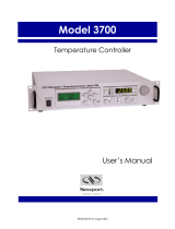
Figure 2.1 TCM-39032 Back Panel
ANLG GND
VOLT LIM
CUR LIM
TEMP LIM
BOOSTER
DGTL GND
CONT SIG
14
15
11
12
13
10
9
TE MDL-
TE MDL+
SNSR -
SNSR +
SNSR SHLD
TE SHLD
1,2
6
7
8
3,4
5
10 Am
THERM RANGE
100 Am
SENSOR SELECT
THERM
RTD
LM335
AD590
TE CONTROLLER
39032 32 WATT
Sensor Select
Switch
Thermistor Range
Select SwitchTEC Connector
Module Locking Screw
Module Locking Screw

OPERATION
SENSOR SELECT Switches
6 TCM-39032
CHAPTER 2
SENSOR SELECT Switches
The SENSOR SELECT and THERM RANGE switches are used to select sensor
type and, in the case of thermistor sensor, the source current level. Table 2.1
shows the SENSOR SELECT ( THERM RANGE) positions and corresponding
position code. When the sensor switch is changed during TEC mode operation,
the new sensor position code will be indicated on the TEC display for three
seconds.
Table 2.1 SENSOR SELECT Switch Positions.
The 10 µA and 100 µA designations are for the current source level; thermistor
sensor type is implied. When using a thermistor, the supply current depends on
the thermistor operating temperature range and the required temperature
resolution.
The AD590 sensor operates as a current source which is proportional to the
sensed temperature. The LM335 sensor operates as a voltage source which is
proportional to the sensed temperature. Both of these sensors are approximately
linear over their operating ranges. When they are used, the constants C1 and C2
are used for a two-point conversion.
SWITCH Position Code
100 µA -- 01
10 µA -- 02
LM335 -- 03
AD590 -- 04
RTD (with TSC-595) -- 05

OPERATION
TEC Connector
06_03 TCM-39032 7
CHAPTER 2
TEC Connector
At the right of center, on the TCM-39032 back panel, the user will find the 15-pin
D-connector for the TEC MODULE. This connector is used for the input and
output connections, as shown by the pin-out diagram below.
Figure 2.2 Back Panel TEC Connector
TEC Grounding Considerations
DO NOT allow Sensor (-) to connect to TEC Module (-) or TEC Module (+) directly
or through a common ground. Even a momentary connection when the output is
off will cause damage to the instrument and/or device. For the TEC connector, if
any one terminal pin is grounded, then no other terminal pin should be grounded.
Instrument damange caused by shorting these pins is not covered under warranty.
TEC Interlock
On the back panel TEC connector, pins 13 (TEMP LIMIT) and 15 (DIGITAL GND)
form a type of interlock. These two pins are normally not connected
(open circuit)
and must remain open for the TEC output to be on. If there is a short circuit
between these pins, the TEC output will be disabled. When this short circuit is
1
2
3
4
5
6
7
8
9
10
11
12
13
14
15
1, 2 TE Module (+)
3, 4 TE Module (-)
5 TE Module Shield
6 Sensor Shield
7 Sensor (+)
8 Sensor (-)
9 Analog Ground
10 Control Signal
11 Voltage Limit
12 Current Limit
13 Temp. Limit
14 Booster Present
15 Digital Ground

OPERATION
Booster Operation
8 TCM-39032
CHAPTER 2
present, the TEC Interlock Error condition / event will be reported in the TEC
Event Status REgister and the TEC Condition Status Register.
This circuit is useful for remote monitoring of temperature, and therefore is labeled
TEMP LIMIT on the back panel connector. This interlock is intended for use with
an external current booster. A switch or control circuit of the user’s own design is
required. It is left as an option which the user may or may not employ.
Booster Operation
The TCM-39032 may be used to control a booster current source which accepts a
control signal of up to +10.0 volts. A booster current source may be required if the
TCM-39032's +
4 A, 32 W output is not adequate to control a thermal load.
Whenever a connection is present between the BOOSTER PRESENT (pin 14)
and DIGITAL GROUND (pin 15) of the back panel TEC Input/Output connector,
the BOOST CONTROL signal voltage will be available for controlling a booster
TEC current source.
The Booster Enabled condition is reported in the TEC Condition Status register.
When the GPIB option is implemented, this condition may be used to trigger a
service request.
The booster current source should use the control voltage which is available
between the BOOST CONTROL (pin 10) and AGND (pin 9) of the back panel
TEC connector.
When the BOOSTER PRESENT signal is connected to DIGITAL GROUND, the
LIM I value may be increased above the normal operation maximum of 4.0 Amps,
to a maximum of 10.0 Amps. This is permitted for operation with a booster current
source so that the CONTROL SIGNAL voltage may be +
10.0 volts. The
CONTROL SIGNAL voltage is linearly proportional to the control current, which is
limited by the LIM I parameter.
Whether or not a booster current source is used, the TCM-39032 uses a sensor
for controlling the temperature. The feedback loop GAIN may require adjustment
when a booster current source is used. This is because a booster current source
may be used with different thermal loads than those found with normal TCM-
39032 operation, and those loads may require larger or smaller GAIN values in
order to settle to the set temperatures in a desirable fashion. See the LDC-3900
Instruction Manual for setting the GAIN value.
During operation, if the status of the connection between the BOOSTER
PRESENT and DIGITAL GROUND changes, this event will be reported in the
TEC Event Status Register. When the GPIB option is implemented, this event may
be used to trigger a service request.

OPERATION
Booster Operation
06_03 TCM-39032 9
CHAPTER 2

OPERATION
Booster Operation
10 TCM-39032
CHAPTER 2
/