Deagostini Spitfire User guide

Type
User guide

The Deagostini Spitfire is a meticulously detailed model kit that allows you to build a stunning replica of the iconic World War II fighter plane. With over 120 stages of assembly, you'll experience the thrill of creating a historically accurate model from scratch. The kit includes high-quality parts, such as metal sheets, wooden strips, and transparent sheets, ensuring a realistic and durable model.

The Deagostini Spitfire is a meticulously detailed model kit that allows you to build a stunning replica of the iconic World War II fighter plane. With over 120 stages of assembly, you'll experience the thrill of creating a historically accurate model from scratch. The kit includes high-quality parts, such as metal sheets, wooden strips, and transparent sheets, ensuring a realistic and durable model.

1
Build the Spitfire: Step-By-Step
Pack 31
Stages 119-122
2
Build the Spitfire: Step-By-Step
Contents
Stage Parts Pages
119
1 - Rear wheel support
2 - Rear wheel hub
3 - Rear wheel
4 - Transparent sheets for canopy
414-416
120 1 - Rear of canopy and tracks
2 - Brass wire 1 x 100mm 417-420
121
1 - Canopy frames
2 - Transparent sheet for canopy
Servo kit (optional)*
421-424
122 1 - Wing air intake
2 - Mirror 425-427
*Go online at www.model-space.com for details on how to purchase the servo kit.
414
Build the Spitfire: Step-By-Step
Cut three 5mm strips and glue them onto the
lower part of the tail as shown. Cut to shape with a
knife, then smooth with a sanding block (see inset
photo) until they are flush with the fuselage.
Find fuselage plates 1, 2 and 4 (from Stage 86),
7 and 5 (from Stages 89 and 100), 22 and 23 (from
Stage 102), and 25 and 26 (from Stage 104). Add
details with the rivet marker as on the templates.
2
This stages parts You will need
Stage 119
1 - Rear wheel support
2 - Rear wheel hub
3 - Rear wheel
4 - Transparent sheets for canopy
Knife
Glue
Nails
Awl
Sanding block
3
4
12
1
Small file
Rivet marker
Rod
Marker Pen
Wooden block
415
Build the Spitfire: Step-By-Step
5
Make any necessary adjustments, then sand, glue
and nail plate 7 in place. The arrows indicate the
position of the nails in the corners.
Sand the inside of plate 22, then glue in place
and secure with nails in the corners. Do the same
with plate 23.
Place fuselage plate 7 against the body. With
a marker pen, draw a line where the plate
overlaps the edge. Cut the plate with a knife so
that it fits neatly.
Bend fuselage plate 22 around the tail. Use a
piece of wood to bend the metal to the angles of
the body.
34
56
416
Build the Spitfire: Step-By-Step
Arrange plates 4, 5 and 7 on the side of the
fuselage, as shown in the photo. Make sure they
fit, then sand, glue and nail them in place.
Fit plates 25 and 26 beneath the right stabiliser.
Use a piece of wood to bend them into shape,
then sand, glue and nail them in place.
Ensure that plates 4 and 5 fit correctly, then sand,
glue and nail them in place.
This is how your model will look at the completion
of this stage. Keep any spare materials and parts
for future use.
78
10
9
11
Find plates 1 and 2. Bend them over a rod so that
they take the shape of the tail. Sand, glue and nail
the plates in place.
417
Build the Spitfire: Step-By-Step
Find the fuselage plate from Stage 86 and lay it on
the underside of the nose. Bend it and adjust it,
then sand and glue it in place.
This stages parts You will need
Stage 120
1 - Rear of canopy and tracks
2 - Brass wire 1 x 100mm
Glue
Nails
Sanding block
Small round file
Tweezers
Find some 3 x 3mm strips. Cut pieces to fit in the
lower part of the nose, as shown. Glue them in
place and when dry, use a sanding block to sand
them flush with the curve of the fuselage.
1
2
1 2
Knife
Hammer
Rivet marker
418
Build the Spitfire: Step-By-Step
Find the four smaller tail plates supplied with
Stages 108, 110, 112 and 114. Adjust as necessary
and glue them to the top and bottom of the tail
stabilizers, nearest to the tailfin, as pictured. The
inset photo shows the underside of the tail.
5
Find the four tail plates provided with Stages 108,
110, 112 and 114 – they fit on the upper and lower
sides of the tail stabilizers. Test-fit them in place
first, then when you are sure that they fit correctly,
glue them in place. The inset photo shows the
underside of the tail.
4
Find the fuselage plates for the underside of the
nose from Stages 115 and 116. Bend both plates
so that they follow the shape of the body. When
you are sure that they fit correctly, sand and glue
them in place.
3
Take the two pieces of the base fixing structure
provided with Stage 82 and place a spider nut in
each. Stick them in place and use a flat wooden
strip as a guide to ensure that the two pieces are
flush with the outer edge.
6
419
Build the Spitfire: Step-By-Step
Find the wing plate 28 from Stage 72, and add the
detailing with the rivet marker according to the
template. Place the plate on the underside of the
wings, then mark and drill out the holes shown.
Sand, glue and nail plate 28 in place.
Turn the wings over and with a round file, file
down the threads of the two spider nuts.
On the inside of the wing, glue 4 x 4mm wooden
strips as shown in the photo to reinforce the base
fixing structure and hold it in place securely.
Find the lower wing plates 27 from Stage 81.
Adjust them to fit in the area of the wing behind
the leading edge, as shown in the photo, then
sand, glue and nail them in place.
7 8
910
420
Build the Spitfire: Step-By-Step
Sand the backs of the pieces that will be stuck to
the wing, then add glue and position the pieces
on the wing, using this photograph as a guide.
Do the same for the other wing and remember to
keep the two wings symmetrical. Keep the J’ piece
safely for Stage 122.
With a knife and hammer, carefully cut the
struts connecting each piece to the metal sheet.
Smooth any rough edges with a small file.
Take the metal sheet of wing embellishments from
Stages 103 and 104. This picture will help you to
identify each of the pieces.
After completing this stage, the fuselage and
the wings will now look like this. Keep any spare
materials for future use.
D
I
E
IF
GH
B
B
B
B
B
B
B
A
A
A
11 12
13 14
421
Build the Spitfire: Step-By-Step
Steps 1- 6 are to be completed only if you want
to fit the optional servo kit to raise and lower
the landing gear. Find the base of the mount
from Stage 69, which is screwed inside the
undercarriage, as shown.
If you are installing a servo, take the mount from
Stage 69. Screw the servo to the housing as shown
in the photo.
This stages parts You will need
Stage 121
1 - Canopy frames
2 - Transparent sheet for canopy
Servo kit (optional)*
Screwdriver
Pliers
Glue
Drill
Sandpaper
12
1 2
Nails
Optional servo kit*
*Go online at www.model-space.com for details
on how to purchase the servo kit.
422
Build the Spitfire: Step-By-Step
Screw the connectors into the two holes in the
disc, and pass the straight ends of the transmission
rods through the holes in the connectors. Hook
the bent end of the rods through the holes in the
suspension joints (arrows).
Drill two holes in the plastic disc (supplied with
the servo), at the circled points. Make sure they
are aligned with each other. Cut two sections of
the rod from Stage 67, and bend the ends over
with pliers to the shape shown above. These will
be used as the transmission rods.
Secure the assembly to the base with 13mm screws
(Stage 94). Pass the cable through the circled hole,
out of the underside of the wing (inset). If you are
not fitting the servo; take the rod from Stage 67
and bend one end to 90 degrees. Hook this end
through one of the suspension joints. Cut to length
(red line) and bend the other end to 90 degrees.
Then hook this end through the other suspension
joint. This will hold the landing gear in position.
Place the centre of the disc onto the projecting
part of the servo and secure with the large screw
supplied with the servo kit.
65mm
55mm
3 4
56
423
Build the Spitfire: Step-By-Step
With pliers, insert a nail into the hole in the tab,
which will act as a hinge for the aileron.
Ensure that the corners line up with the ribs of the
wing, as shown in the photo.
To make the ailerons, take plates 29 and 30 from
Stages 83, 88, 90 and 93. Make a hole for a nail
in the tabs at each end, then bend them at 90
degrees. Add 3 x 3mm strips at intervals along
the length of the plates. Make sure the position
of the strips aligns with the ribs of the wing.
Glue on additional strips to hold the plates to the
ribs of the wing.
7 8
910
424
Build the Spitfire: Step-By-Step
This picture shows the underside of the wings
with the ailerons in place.
Take the remaining details from the previous
stage and glue them in place. Take the upper wing
plates 4 from Stage 84 and sand, glue and nail
them on each half of the wing. Insert and secure
the elevator flaps at the rear.
Take the top wing plates 2 from Stages 58 and 75.
Test-fit, sand, glue and nail them in place (red
arrows). Make the holes for the wing mounting
screws (blue arrows). If you are fitting the servo,
you will need to adjust the shape of the plates to
accommodate it, as shown in the inset.
This is how the top of the wings will look once
this stage of assembly is complete. Keep any
remaining materials for future use.
11
B
C
C
B
C
12
13 14
425
Build the Spitfire: Step-By-Step
Take the base plate from Stage 65 and insert two
spider nuts (captive nuts). Glue the plate into
place using 3 x 5mm strips as reinforcement (as
shown). When dry, sand the strips so they are flush
with the fuselage.
Put a plate on the underside of the fuselage (outer
dotted lines). Draw the shape of the bottom of the
fuselage (inner lines) and cut it out. Make a hole
for the LED (arrow) and press along the centre
with the rivet marker. Sand, glue and nail in place.
This stages parts You will need
Stage 122
1 - Wing air intake
2 - Mirror
Glue
Sandpaper
Knife
Awl
Pliers
Scouring pad
Rivet marker
Primer
Red and green
paint
File
1
2
1 2
426
Build the Spitfire: Step-By-Step
Find the plates 8, from Stages 115 and 116. Bend
them to fit to the shape of the lower fuselage.
Then sand and glue in place.
Cut a spare plate to make two pieces to cover the
underside of the tail section of the fuselage. Bend
them slightly, then sand and glue in place. Rub the
edges lightly with a scouring pad (inset) to finish.
Take fuselage plates 21 (from Stages 89 and 100).
Sand, glue and nail them in place as shown. Find
the round ‘J’ piece saved from earlier, and glue it
in place around the hole for the LED.
Check the position of the wing in the fuselage.
Make any necessary adjustments to the fit, so that
the holes for the spider nuts align with those in
the body.
43
56
Find the cockpit door from Stage 92. Sand
smooth and glue a 30mm length of 1mm brass
wire to the inside of the door. For a painted finish:
apply a primer and paint the inside of the door
green, and paint the brass wire red, as shown.
ø 1mm
7 8
Hold the door in position on the fuselage and
mark the position where the hinges will be. Then
make holes above and below those marks.
J
427
Build the Spitfire: Step-By-Step
A
A
D
C
B
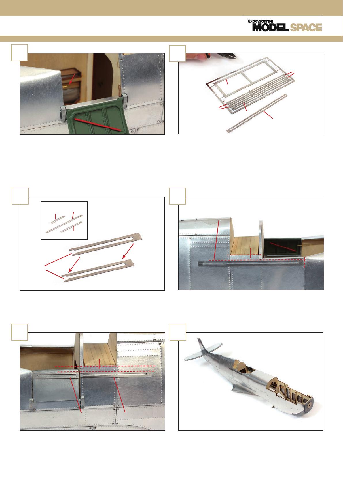
Glue one hinge in place, and insert the projection
on the door into the hole in that hinge. Hold the
door in place and glue the second hinge into
position, over the second projection and into the
two holes. Then, make a hole and glue a small
piece of brass wire in it (arrow).
Find the metal pieces from Stage 120. Cut out
parts A, B and C with pliers. Sand the pieces to get
rid of any remainder of the connecting sprues.
910
With a file, smooth the inside and outside edges
of the ‘B’ and ‘C’ tracks. Glue them on the left side
of the fuselage, 5mm below the cockpit edge,
making sure both are correctly aligned.
To make the tracks for the canopy, glue the ‘A‘
pieces together. Do the same for parts ‘B’ and ‘C’.
The ‘B’ pieces will fix to the cockpit door.
This photo shows how the fuselage will look at the
end of this stage. Keep any surplus parts safely for
later use.
With a file, smooth the inside and outside edges
of the ‘A’ track. Glue it on the right side of the
fuselage, as shown, 5mm below the cockpit edge.
B
A
BC
11
A
B
C
12
13 14
5mm
5mm
  • Page 1 1
  • Page 2 2
  • Page 3 3
  • Page 4 4
  • Page 5 5
  • Page 6 6
  • Page 7 7
  • Page 8 8
  • Page 9 9
  • Page 10 10
  • Page 11 11
  • Page 12 12
  • Page 13 13
  • Page 14 14
  • Page 15 15
  • Page 16 16

Deagostini Spitfire User guide

Type
User guide

The Deagostini Spitfire is a meticulously detailed model kit that allows you to build a stunning replica of the iconic World War II fighter plane. With over 120 stages of assembly, you'll experience the thrill of creating a historically accurate model from scratch. The kit includes high-quality parts, such as metal sheets, wooden strips, and transparent sheets, ensuring a realistic and durable model.

Ask a question and I''ll find the answer in the document

Finding information in a document is now easier with AI