Page is loading ...

KVH, TracPhone, and the unique light-colored dome with dark contrasting baseplate are registered trademarks of KVH Industries, Inc.
All other trademarks are property of their respective companies. The information in this document is subject to change without notice.
No company shall be liable for errors contained herein. © 2011-2018 KVH Industries, Inc., All rights reserved.
54-0754 Rev. C | 72-0487, 72-0739, 72-0741
1
TracPhone V3/V3IP/V3HTS LNB
Replacement Instructions
Technical Support
If you need technical assistance, please contact KVH Technical Support:
Europe, Middle East, Africa, Asia-Pacific:
Phone: +45 45 160 180
Email: [email protected]
North/South America, Australasia:
Phone: 1 866 701-7103 (U.S. only) or +1 401 851-3806
Email: [email protected]
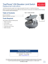
The following instructions explain how to replace
the LNB in a TracPhone
®
V3/V3-IP/V3-HTS
antenna.
NOTE: Your antenna might have parts that differ from
those pictured in this document. Such differences have no
bearing on the instructions unless noted otherwise.
Tools Required
This procedure requires the following tools:
• Phillips screwdrivers
• 7/16" open-end wrench
• 7/16" torque wrench set to 15 in.-lbs
Figure 1: TracPhone Antenna LNB (V3-IP Shown)

2
Step 1 - Disconnect Power and Remove the
Radome
Follow the steps below to swap out either an old or
current model LNB.
1. Power off and unplug the ICM, or modem and
control unit, to disconnect power from the
antenna.
2. Remove and discard the three #10-32 screws
securing the radome to the baseplate (see
Figure 2). Carefully lift the radome straight up
until clear of the antenna assembly and set it
aside in a safe place.
If you keep the radome topside, secure it with a
lanyard to prevent it from falling overboard.
Do not place the radome on a hot steel deck –
the heat may warp the radome.
CAUTION
For your own safety, be sure to disconnect power
from all wired components before performing
this procedure.
Figure 2: Remove the Radome (V3-IP Shown)
#10-32 Screw (x3)

3
Step 2 - Identify the LNB Type
There are four possible LNB types (see Figure 3). The
replacement instructions are identical for each with
one exception - the Legacy LNB must be replaced
with an LNB-1 with attached filter. Legacy LNBs are
no longer available.
NOTE: Type 2 LNBs are labeled as such. Older LNBs are
not labeled.
Important!
Be sure to replace the LNB with an LNB of the same
type, with the exception of the Legacy LNB. The
Legacy LNB must be replaced with an LNB-1 with
filter.
Figure 3: LNB Types (from oldest to newest)

4
Step 3 - Replace the LNB
Follow the steps below and refer to Figure 4 to replace
the LNB.
1. Using a 7/16" open-end wrench, disconnect the RF
cable from the LNB. To avoid stressing the cable,
hold the top of the connector with your fingers
while loosening.
2. Using a Phillips screwdriver, remove and discard
the four M4 screws securing the LNB to the OMT.
Remove the defective LNB and its O-ring gasket.
3. Secure the replacement LNB to the OMT using
four new M4 screws (supplied in kit), making sure
that the LNB notch, if present, faces the OMT.
Tighten the screws to approximately 21 in-lbs (2.4
N-m) of torque.
4. Reconnect the RF cable to the LNB making sure
that the RF cable is aligned to prevent any
interference when the feed assembly rotates.
Hand-tighten, then tighten with a 7/16" torque
wrench set to 15 in.-lbs.
5. Inspect the inside of the antenna to make sure you
have not left any tools or debris inside.
6. Reinstall the radome onto the antenna securing it
with the three new #10-32 screws (supplied in kit).
7. Reconnect power to the antenna.
8. Test the system for normal operation. If the
problem persists, contact KVH Technical Support.
The replacement procedure is complete!
Important!
Before removal, note the orientation of the LNB, as
shown in Figure 4, and be sure to match this
orientation when installing the replacement LNB.
Important!
Do not remove the Kapton tape from the
replacement LNB and ensure the new O-ring
gasket remains in place during the installation.
Figure 4: LNB RF Cable and Mounting Screws (LNB-2 shown)
/