Page is loading ...

TD505005EN
9/23/2015
Catalog #
Project
Comments
Prepared by
Type
Date
Sure-Lites
SPECIFICATION FEATURES
HOW TO SPECIFIY
DIMENSIONS
DESCRIPTION
The Sure-Lites Emergency Light (SEL) series is designed
to reduce egress system cost and maintenance as well as improve
reliability. Key features include long life LED’s, proprietary adjustable
accuLED optics, a nickel cadmium battery and an Eagle Eye self-
diagnostics option. The Patented external battery disconnect and
easy hang features reduce installation time and cost.
ELECTRICAL
- Dual Voltage Input
120/277 VAC, 60Hz
- 240 VAC capable with 48 hour
recharge time
- External Battery Disconnect
- Brownout circuit
- Low voltage disconnect
- Overload / Short Circuit
protection
- 4.8V Battery back-up
- Eagle Eye self diagnostic option
HOUSING CONSTRUCTION
- Components injection molded,
color stable, high impact
thermoplastic
- White or black textured finish
- Black only available with self
diagnostic
- EZ Hang feature facilitates fast
installation
- Suitable for ceiling or wall mount
applications
- Universal J-box mounting
pattern
- Keyhole mounting slots
- Aesthetically designed with
thin profile
BATTERY
- Sealed Nickel Cadmium
- Full Recharge Time,
24 hours (max.)
- 0° to 40°C (32° to 104°F)
WARRANTY
- Five-year warranty
- Prorated 7-year battery warranty
CODE COMPLIANCE
- UL924 Listed
- Damp Location
- Life Safety NFPA 101
- NEC/OSHA
- Most State & Local Codes
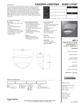
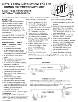
Sure-lites LED emergency light with nickel cadmium battery, external battery disconnect, and adjustable
optics.
SEL Emergency
Light
LED Emergency Light
Adjustable Optic
Eagle Eye Self
Diagnostics
SEL
SEL25
ORDERING INFORMATION
SAMPLE NUMBER: SEL25, SEL25SD, SEL25BKSD
Series Coverage Battery Color Self Diagnostic
SEL= LED Emergency Light 25=25 feet __=NiCad __=White __=No SD
SD=Self Diagnostic
Series Coverage Battery Color Self Diagnostic
SEL= LED Emergency Light 25=25 feet __=NiCad BK=Black SD=Self Diagnostic
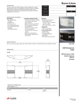
SEL25/SEL25SD
SEL17
14"
[356mm]
12-7/8"
[326mm]
4-3/4"
[121mm]
5-3/8"
[137mm]
11-1/8"
[283mm]
1-3/4"
[45mm]
1-3/4"
[45mm]

SEL25
Sure-Lites
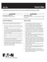
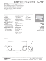
PHOTOMETRY
25ft
3
.1
1
4
.1
1
.1
5
1
6
.1
1
7
.1
1
8
.1
1
9
.1
1
.1
10
1
2.5 1.5 1.5 2.5 2.7 1 .8 0.8 0.4
0.2
0.2
0.2
0.2 0 .3 0.5 1.1 2.2
2.9 2 .1 1.4 1.7 2.8 2.5 1.4 0.7 0.3
0.2
0.2 0 .2 0.2 0. 3 0.7 1.4 2.5 2.8 1.7 1.4 2.1
2.9 2 .2 1.1 0.5 0.3 0.2 0.2
2.3 1.4 1 .4 2.3 2.5 1.8 0.9 0.4
0.2 0 .2 0.2 0 .2 0.3 0.6 1.2 2.1 2.6 1.9 1.2 1.6 2.5 2.3 1.5 0.7 0.4
0.2 0 .2
0.2
0.2 0 .4 0.7 1.5 2.3 2.5 1.6 1.2 1.9 2.6 2.1 1.2 0.6 0.3 0.2
0.2
1.2 0.9 0 .9 1.2 1.5 1.2 0.7 0.4
0.2
0.2
0.2
0.2 0 .3 0.5 0.9 1.3 1.4 1.1 0.9 0.9 1.3 1.4 1.0 0.6 0.3 0.2
0.2 0 .2 0.2 0. 3 0.6 1.0 1.4 1.3 0.9 0.9 1.0 1.4 1.3 0.8 0.5 0.3
0.2 0.2
SEL25
X Y Z Orient Tilt
-0.5 0.25 7. 5 125 27
0.5 0.25 7. 5 55 27
16.5 0.211 7. 5 125 27
1 7. 5 0.212 7. 5 55 27
33.5 0.172 7. 5 125 27
34.5 0.173 7. 5 55 27
50.5 0.132 7. 5 125 27
51.5 0.135 7. 5 55 27
67.5 0.093 7. 5 125 27
68.5 0.096 7. 5 55 27
84.5 0.054 7. 5 125 27
85.5 0.058 7. 5 55 27
101.5 0.015 7. 5 125 27
102.5 0.019 7. 5 55 27
25 ft.
***The “Rule of Thumb” spacing guidelines are designed to achieve 1 foot-candle average and 0.1 foot-candle minimum with a 40:1 maximum/minimum ratio. The
corridor used is 100 feet long, 9 foot ceiling with a 6 foot wide walkway and 3 foot path of egress. The reflectances are 80% ceiling, 50% walls and 20% floors. The fixture
mounting height is 7.5 feet. Cooper Lighting assumes no responsibility for local requirements or specific project variables. This is a guideline to be used as a design aid, not
as guarantee of any code compliance.
TECHNICAL DATA
Mechanical Housing
All components are injection molded with a
color stable, high impact thermoplastic resin.
The surface is textured to improve aesthetic
appearance. The housing construction is
designed with snap-fit components and
reinforcement ribs to provide maximum
strength at minimum installation effort.
The mounting hole pattern is universal to
junction box requirements and is suitable for
both wall and ceiling mount applications.
EZ Key – External Power
Disconnect
Prevents the battery from cycling during the
construction phase and ensures battery is not
drained from power cycling.
EZ Hang – Mounting Feature
The hands-free EZ Hang feature allows the
installer to hang the emergency light face
from the back plate in order to easily and
efficiently make the power connections.
Eagle Eye™ Self Diagnostics
The Eagle Eye self-diagnostic software will
automatically perform all tests required by
UL924, and NFPA101. The system indicates
the status of the emergency light at all times
using the LED indicator. A 90 minute battery
power (emergency mode) simulation test will
occur once every 12 months. A 30 second
battery power simulation test will occur
every 30 days.
The Solid-State microprocessor based
system has the ability to accurately
detect and warn of system failures, plus it
incorporates all of the standard electronic
features that sets Sure-Lites apart from
its competition. Eagle Eye self diagnostic
software automatically performs all testing
required by the NFPA 101 Life Safety
Code and systematically calibrates itself
in the field, reducing installation labor and
eliminating manual calibration errors.
Low Voltage Disconnect
The low-voltage circuitry disconnects the
lighting load to protect the battery after run
times in excess of the 90-minute UL limit.
The disconnect remains in effect until normal
utility power is restored preventing deep
battery discharge.
Brownout Circuit
The brownout circuit on the SEL emergency
light monitors the flow of AC current to the
unit and activates the emergency light heads
when a predetermined reduction of AC
power occurs.
Warranty
SEL units are backed by a five-year warranty
on the fixtures.
EZ Key EZ Hang

Eaton
1121 Highway 74 South
Peachtree City, GA 30269
P: 770-486-4800
www.eaton.com/lighting
Specifications and
dimensions subject to
change without notice.
SEL25
Sure-Lites
SELF DIAGNOSTIC TESTING OPERATIONS
The Sure-Lites Eagle Eye Self Diagnostics is continuously monitoring your emergency fixture, and will signal any failure through the 3 color
indicator LED.
Initial Operation:
When the unit is first powered up it will go into a 24 hour fast charge and indicator LED will pulse green. Once the unit has fully charged it will
perform a self calibration. After self calibration, the LED will change to steady green indicating the unit is fully charged and float charging the
battery to maintain readiness.
Automatic Testing:
The unit will perform a battery capacity, lamp/LED, and charge circuit test every 30 days for 30 seconds. During this time, the indicator LED will
change to a steady yellow. It will perform a full battery capacity (90 minute) test once per year. During this time, the indicator LED will change to
a blinking yellow.
Manual Testing:
• 10 Second “Installation” test – Press and release the test button once during fast charge (blinking green) to initiate a 10 second quick test. The
sign will switch to emergency mode for 10 seconds allowing the installer to verify proper installation of the unit, and the LED indicator will
turn solid yellow.
• 30 Second Test - Press and release the test button once during float charge (steady green). The indicator LED will turn steady yellow to
indicate the unit is performing a 30 second test of the batteries and lamps/LEDs.
• 90 Minute Test - Press and release the test button a second time during a 30 second test (steady yellow) to change to a 90 minute test. During
this test, the LED indicator will change to blinking yellow, and the circuit will perform a full battery capacity, charge circuit, and LED test.
• Canceling Test – Press and release the test button during the 90 minute test (flashing yellow) to return the fixture to its original state (fast
charge or float charge)
Laser Test:
The SEL SD products are equipped with a Laser Test function that allows the unit to be manually tested without the need to physically press the
test button. Shining a laser pointer in the hole marked “LASER TEST” on the bottom of the unit has the same effect as a press and release of
the test button.
Clearing Failure Codes:
• A battery failure (LED two blink red) can be cleared by replacing the battery. Disconnecting the battery and AC power, or performing a full
90 minute discharge will reset the error code, however, it will return if the battery is faulty
• Charge Circuit (LED three blink red) and lamp/LED failure (LED four blink red) will clear when the unit successfully passes a manual or
automatic 30 second test.
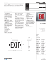
SELF DIAGNOSTIC TESTING OPERATIONS
Indicators:
• LED Off - No power to unit, emergency mode.
• LED Steady Green - Unit is fully charged and is float charging the battery to maintain readiness.
• LED Green Pulse - Unit is in a 24 hour fast charge of the battery.
• LED Two Blink Red - Battery has failed a capacity test, or the battery is disconnected. See “Clearing Failure Codes” above.
• LED Three Blink Red - Battery charge circuit has failed. See “Clearing Failure Codes” above.
• LED Four Blink Red - Lamps have burned out, or on an EXIT/Combo, 50% or more of the LEDs have failed. See “Clearing Failure Codes” above.
• LED Steady Yellow - 30 second test or 10 second quick test (Fast Charge only).
• LED Blinking Yellow - 90 minute test.
Maintenance:
None required. Replace the batteries as needed according to ambient conditions. However, we recommend that the equipment be tested
regularly in accordance with local codes.
OFF - EMERGENCY
MODE / POWER OFF
2 BLINK RED -
BATTERY FAILURE
STEADY GREEN -
FULL / FLOAT
CHARGE
STEADY BLINK YELLOW
- 90 MINUTE TEST
3 BLINK RED - CHARGE
CIRCUIT FAILURE
4 BLINK RED - LAMP/
LED FAILURE
STEADY YELLOW -
QUICK TEST
STEADY BLINK
GREEN - FAST
CHARGE
SURE-LITES
/