Page is loading ...

INS #
Brand Logo
reversed out of
black
INS #
IB505050EN 049-303
Installation Instructions for the Sure-Lites LPX Combination Exit/Emergency Lights
and Exits
WARNING
Risk of Fire/Electric Shock
If not qualified, consult an electrician.
WARNING
Risk of Electric Shock
Disconnect power at fuse or circuit breaker before
installing or servicing.
Important Safeguards
WHEN USING ELECTRICAL EQUIPMENT, BASIC SAFETY
PRECAUTIONS SHOULD ALWAYS BE OBSERVED INCLUDING
THE FOLLOWING.
1 READ AND FOLLOW ALL SAFETY INSTRUCTIONS
2 Do not use outdoors.
3 Do not use in hazardous locations, or near gas or electric
heaters.
4 Do not let power supply cords touch hot surfaces.
5 Do not use this equipment for other than the intended use.
6 Installation is to be performed only by qualified personnel.
7 Install in accordance with National Electric Code and local
regulatory agency requirements.
8 The use of accessory equipment not recommended by the
manufacturer may cause an unsafe condition.
9 Equipment should be mounted in locations and at heights
where it will not readily be subjected to tampering by
unauthorized personnel.
10 SAVE THESE INSTRUCTIONS
MAX MOUNTING HEIGHT:
17.24 FT
WALL MOUNT INSTALLATION
1 Extend unswitched 24 hour AC supply of rated voltage to
junction box (by others). Leave at least 18 inches of slack.
Circuit should not be energized at this time.
2 Remove the stencil face and lens assembly by applying a
screwdriver to the snaps located at the top and bottom of
the stencil face.
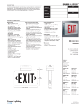
3 Knock out the appropriate mounting pattern and wire pass
hole to match junction box. Use the integrated wire hook
in the backplate to hold the wires in place so that there is
no shadowing on the face of the sign (see Figure 1).
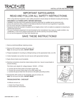
4 Connect power supply and ground in accordance with
local codes. Wire connections as follows: 277VAC/240VAC
line to Orange lead or 120V line to Black lead; Neutral or
240V (Common) to white lead (see schematic). Cap unused
line lead.
Note: Connections must be the enclosure rated area of the
frame (top left corner) or junction box (see Figure 1).
5 Mount to junction box.
6 Determine which color sign face is needed. If red is
needed, proceed to step 9.
7 If green is the desired color, remove the red lens from
the stencil and replace it with the green lens provided.
(Installation is the reverse of removal.).
8 On the LED circuit board, locate the red/green jumper (See
Schematic).The jumper should be in the red position per
the silk screen printing on the board. Pull gently upward
on the jumper, then shift it one pin over to activate the
green LEDS.
9 If the unit has remote capacity, LED remotes can be
connected using the violet (+) and yellow (-) wires.
(See Schematic).
10 Energize AC supply, LED display will come on.
11 Replace the stencil cover assembly.
12 Remove EZ Key to connect battery. Battery will not charge
with EZ key in place. Allow 24 hours for charging with 120
or 277V input, 48 hours with 240V input.
CEILING OR END MOUNT INSTALLATION
1 Extend unswitched 24 hour AC supply of rated voltage to
junction box (by others). Leave at least 18 inches of slack.
Circuit should not be energized at this time.
2 Remove the stencil face and lens assembly by applying a
screwdriver to the snaps located at the top and bottom of
the stencil face.
3 If mounting the canopy to the top, remove the canopy
hole cover plate on the top. If locating the canopy on the
side, first remove the left side head by disconnecting the
LED lamp wires from the PCB (see Schematic) and gently
pulling on the head mount (see Figure 2). The head may
now be mounted in one of the 3 locations on the top (see
Figure 2). The center top mounting point can be accessed
by removing the cover. The left and right top mounting
points can be accessed by removing the small knock outs.
The left side head can also be moved to the top, to make
the fixture symmetric. Cover the unused holes with the

2
EATON IB505050EN Installation instructions
Installation Instructions for LPX Combination Exit/Emergency Lights and Exits
canopy hole cover plates.
4 If double face sign is required, convert the single face sign
supplied. Replace back plate with extra stencil and color
sheet supplied with the sign.
5 Place the canopy nose through the mounting hole until the
side of the frame touches the canopy. Lock the frame onto
the canopy by sliding the frame in a direction parallel to the
canopy length toward the narrow end of the mounting hole.
Slide the frame until both snaps engage the canopy nose
preventing any motion back out of the hole.
6 Mount mounting strap to junction box by choosing proper
slots and using screws supplied with junction box.
7 Feed the wires through the canopy.
Note: Connections must be the enclosure rated area of the
frame (top left corner) or junction box (see Figure 1).
8 Connect power supply and ground in accordance with
local codes. Wire connections as follows: 277VAC/240VAC
line to Orange lead or 120V line to Black lead; Neutral or
240V (Common) to white lead. Ground to Green screw on
mounting strap. Cap unused line lead.
ENCLOSURE RATED AREA.
WIRE CONNECTIONS
SHOULD BE MADE HERE
OR IN JUNCTION BOX.
DO NOT MAKE WIRE
CONNECTIONS IN
SIGN FACE
INTEGRATED WIRE HOOK
JUNCTION
BOX
KNOCK
OUTS
TO JUNCTION BOX
CANOPY
HOLE PLUG
REMOVE KOS
TO MOUNT
HEAD
MOUNTING
STRAP
TO
JUNCTION
BOX
Figure 1
9 Connect the canopy to the mounting strap using the screws
provided.
10 Determine which color sign face is needed. If red is needed,
proceed to step 13.
11 If green is the desired color, remove the red lens from
the stencil(s) and replace it with the green lens provided.
(Installation is the reverse of removal.).
12 On the LED circuit board, locate the red/green jumper (See
Schematic).The jumper should be in the red position per the
silk screen printing on the board. Pull gently upward on the
jumper, then shift it one pin over to activate the green LEDS.
13 If the unit has remote capacity, LED remotes can be
connected using the violet (+) and yellow (-) wires. (See
Schematic).
14 Energize AC supply, LED display will come on.
15 Replace stencil, colored lens.
16 Remove EZ Key to connect battery. Battery will not charge
with EZ key in place. Allow 24 hours for charging with 120 or
277V input, 48 hours with 240V input.
Figure 2

Eaton
1121 Highway 74 South
Peachtree City, GA 30269
P: 770-486-4800
www.eaton.com/lighting
© 2017 Eaton
All Rights Reserved
Printed in USA
Publication No. IB505050EN
August 3, 2017 12:31 PM
Eaton is a registered trademark.
All trademarks are property
of their respective owners.
Product availability, specifications,
and compliances are subject to
change without notice
MAINTENANCE
None required. Replace the batteries as needed according
to ambient conditions. However, we recommend that the
equipment be tested regularly in accordance with local codes.
NOTE: Servicing of any parts should be performed by qualified
personnel. Only use replacement parts supplied by Eaton’s
Lighting business.
CAUTION: This equipment is furnished with a sophisticated low
voltage battery dropout circuit to protect the battery from over
discharge after its useful output has been used. Allow 24 hours
recharge time if connected to 120 or 277V, 48 hours with 240V,
after installation or power failure for 90 minute testing.
TROUBLE SHOOTING GUIDE
If LED display or charge indicator LED does not illuminate,
check the following:
• Check AC supply – verify that unit has 24 hour AC supply.
If LEDs do not light in emergency mode but Charge indicator
LED is on before test:
• Unit is shorted or battery is not connected.
• Battery discharged. Permit unit to charge for 24 hours (120
or 277V) or 48 hours (240V) and then re-test.
If following the above trouble shooting hints does not solve
your problem, contact your local Eaton Lighting representative
for assistance.
WARRANTIES AND LIMITATION OF LIABILITY
Please refer to www.eaton.com/LightingWarrantyTerms for our
terms and conditions.
ORANGE LEAD - TO 240 OR 277V
WHITE LEAD - TO NEUTRAL OR 240V (COMMON)
BLACK LEAD - TO 120V
BATTERY
2ND BATTERY
(HIGH POWER
MODELS ONLY)
REMOTE HEADS
(NOT INCLUDED)
ON BOARD
LED HEAD
ON BOARD
LED HEAD
POWER
SUPPLY PCB
SHIFT JUMPER TO
CHANGE LEDS
FROM RED TO
GREEN
D4
F2
C1
F1
J1
C2
C3
+
MOV1
MOV2
Y
O
B
W
N
120
277
R
B
041-1418 REV B
-
+
C1
ICSP
CN3
LED4
J1
LED10
RED
GREEN
CN2
BW
+
RMT
-
BATT
BATT
+
-
+
+
CN1
POWER
+
C9
CN6
CN7
JP2
CN4
L1
LED1
LED2
LED3
LED9
LED7
LED8
LED5LED6
CN5
+
JP5
JP4
JP3
Q 11
Schematics
Installation Instructions for LPX Combination Exit/Emergency Lights and Exits
/