Page is loading ...

2506 Galen Drive
Champaign, IL 61821
Voice 217.344.1243 • Fax 217.344.1245
www.cobaltdigital.com
Product Manual
BBG-1022-FS-DSP-OM (V1.1)
Cobalt Digital Inc.
BBG-1022-FS-DSP
BBG-1022-FS-DSP
3G/HD/SD-SDI Standalone Frame Sync
with Audio/Video Processing, DSP Audio Support,
Audio Embed/De-Embed, and CVBS I/O

Copyright
©Copyright 2019, Cobalt Digital Inc. All Rights Reserved.
Duplication or distribution of this manual and any information contained within is strictly prohibited without the express written
permission of Cobalt Digital Inc. This manual and any information contained within, may not be reproduced, distributed, or
transmitted in any form, or by any means, for any purpose, without the express written permission of Cobalt Digital Inc.
Reproduction or reverse engineering of software used in this device is prohibited.
Disclaimer
The information in this document has been carefully examined and is believed to be entirely reliable. However, no responsibility
is assumed for inaccuracies. Furthermore, Cobalt Digital Inc. reserves the right to make changes to any products herein to improve
readability, function, or design. Cobalt Digital Inc. does not assume any liability arising out of the application or use of any
product or circuit described herein.
Trademark Information
Cobalt
®
is a registered trademark of Cobalt Digital Inc.
openGear
®
is a registered trademark of Ross Video Limited. DashBoard™ is a trademark of Ross Video Limited.
Dolby
®
is a registered trademark of Dolby Laboratories, Inc. Linear Acoustic
®
and UPMAX
®
are registered trademarks of
Linear Acoustic, Inc. 2.0-to-5.1 audio upmixer licensed feature uses the AutoMAX-II™ upmix algorithm provided under license
from Linear Acoustic Inc. Other product names or trademarks appearing in this manual are the property of their respective
owners.
Congratulations on choosing the Cobalt
®
BBG-1022-FS-DSP 3G/HD/SD-SDI Standalone Frame Sync with
Audio/Video Processing, DSP Audio Support, Audio Embed/De-Embed, and CVBS I/O. The
BBG-1022-FS-DSP is part of a full line of modular processing and conversion gear for broadcast TV
environments. The Cobalt Digital Inc. line includes video decoders and encoders, audio embedders and de-
embedders, distribution amplifiers, format converters, remote control systems and much more. Should you
have questions pertaining to the installation or operation of your BBG-1022-FS-DSP, please contact us at the
contact information on the front cover.
Manual No.: BBG-1022-FS-DSP-OM
Document Version:
V1.1
Release Date:
December 3, 2019
Applicable for
Firmware Version
(or greater):
V2.083 or greater
Description of
product/manual
changes:
- Update manual for expanded descriptions and operating setup info
regarding Real-Time Loudness Leveling DSP function.
BBG-1022-FS-DSP-OM (V1.1)

BBG-1022-FS-DSP-OM (V1.1) BBG-1022-FS-DSP PRODUCT MANUAL i
Table of Contents
Chapter 1 Introduction . . . . . . . . . . . . . . . . . . . . . . . . . . . . . . . . . . . . . . . . . . . 1-1
Overview ............................................................................................................................. 1-1
Cobalt Reference Guides..................................................................................................... 1-2
Manual Conventions............................................................................................................ 1-2
Warnings, Cautions, and Notes.............................................................................. 1-3
Labeling Symbol Definitions ................................................................................. 1-3
Safety and Regulatory Summary......................................................................................... 1-4
Warnings................................................................................................................. 1-4
Cautions.................................................................................................................. 1-4
EMC Compliance Per Market ................................................................................ 1-4
BBG-1022-FS-DSP Functional Description ....................................................................... 1-5
BBG-1022-FS-DSP Input/Output Formats ............................................................ 1-5
Video Processor Description.................................................................................. 1-7
Audio Processor Description................................................................................ 1-11
Control and Data Input/Output Interfaces............................................................ 1-15
Alarm Function..................................................................................................... 1-16
User Control Interface.......................................................................................... 1-16
Technical Specifications.................................................................................................... 1-16
Warranty and Service Information .................................................................................... 1-20
Cobalt Digital Inc. Limited Warranty .................................................................. 1-20
Contact Cobalt Digital Inc................................................................................................. 1-21
Chapter 2 Installation and Setup . . . . . . . . . . . . . . . . . . . . . . . . . . . . . . . . . . . 2-1
Overview ............................................................................................................................. 2-1
Installing the BBG-1022-FS-DSP....................................................................................... 2-1
Installing Using BBG-1000-TRAY Optional Mounting Tray ............................... 2-1
BBG-1022-FS-DSP Unit Dimensions.................................................................... 2-2
Rear Panel Connections....................................................................................................... 2-2
GPIO, Serial (COMM), and Analog Audio Connections.................................................... 2-5
Chapter 3 Setup/Operating Instructions . . . . . . . . . . . . . . . . . . . . . . . . . . . . . 3-1
Overview ............................................................................................................................. 3-1
BBG-1022-FS-DSP Front Panel Display and Menu-Accessed Control ............................. 3-1
Connecting BBG-1022-FS-DSP To Your Network............................................................ 3-3
Finding a BBG-1022-FS-DSP Device in DashBoard ............................................ 3-4
Control and Display Descriptions........................................................................................ 3-5
Function Submenu/Parameter Submenu Overview................................................ 3-5
Web User Interface................................................................................................. 3-6
Display Theme........................................................................................................ 3-7
Checking BBG-1022-FS-DSP Device Information ............................................................ 3-8
BBG-1022-FS-DSP Function Menu List and Descriptions ................................................ 3-9

ii BBG-1022-FS-DSP PRODUCT MANUAL BBG-1022-FS-DSP-OM (V1.1)
Audio DSP Setup Controls .................................................................................. 3-10
Input Video Controls ........................................................................................... 3-24
Output Video Mode Controls .............................................................................. 3-25
Framesync ........................................................................................................... 3-26
Input Audio Status ............................................................................................... 3-29
Input Audio Routing/Controls ............................................................................. 3-30
Output Audio Routing/Controls .......................................................................... 3-35
Timecode ............................................................................................................. 3-40
Reticules .............................................................................................................. 3-45
Video Quality Events .......................................................................................... 3-48
Audio Detect Events Setup Controls ................................................................... 3-49
Closed Captioning ............................................................................................... 3-50
Character Burner ................................................................................................. 3-51
Moving Box Insertion ......................................................................................... 3-56
Y/C Alignment Controls ..................................................................................... 3-57
Wings Insertion ................................................................................................... 3-58
Keyer ................................................................................................................... 3-59
Ancillary Data Proc Controls .............................................................................. 3-62
COMM Ports Setup Controls .............................................................................. 3-65
Presets .................................................................................................................. 3-67
GPO Setup Controls ............................................................................................ 3-69
Event Setup Controls ........................................................................................... 3-70
Admin .................................................................................................................. 3-74
User Log .............................................................................................................. 3-76
Alarms Setup Controls ........................................................................................ 3-77
Uploading Firmware Using Web Interface and GUI ........................................................ 3-81
Front Panel User Menus....................................................................................... 3-81
Troubleshooting.................................................................................................................3-83
Error and Failure Indicator Overview.................................................................. 3-83
Basic Troubleshooting Checks............................................................................. 3-85
BBG-1022-FS-DSP Processing Error Troubleshooting....................................... 3-85
In Case of Problems ............................................................................................. 3-87

BBG-1022-FS-DSP-OM (V1.1) BBG-1022-FS-DSP PRODUCT MANUAL 1-1
Chapter 1
Chapter 1 Introduction
Overview
This manual provides installation and operating instructions for the
BBG-1022-FS-DSP 3G/HD/SD-SDI 3G/HD/SD-SDI Standalone Frame
Sync with Audio/Video Processing, DSP Audio Support, Audio Embedding/
De-Embedding, and CVBS I/O unit (also referred to herein as the
BBG-1022-FS-DSP).
This manual consists of the following chapters:
• Chapter 1, “Introduction” – Provides information about this manual
and what is covered. Also provides general information regarding the
BBG-1022-FS-DSP.
• Chapter 2, “Installation and Setup” – Provides instructions for
installing the BBG-1022-FS-DSP and setting up its network access.
• Chapter 3, “Setup/Operating Instructions” – Provides overviews
of operating controls and instructions for using the
BBG-1022-FS-DSP.
This chapter contains the following information:
• Cobalt Reference Guides (p. 1-2)
• Manual Conventions (p. 1-2)
• Safety and Regulatory Summary (p. 1-4)
• BBG-1022-FS-DSP Functional Description (p. 1-5)
• Technical Specifications (p. 1-16)
• Warranty and Service Information (p. 1-20)
• Contact Cobalt Digital Inc. (p. 1-21)

1 Cobalt Reference Guides
1-2 BBG-1022-FS-DSP PRODUCT MANUAL BBG-1022-FS-DSP-OM (V1.1)
Cobalt Reference Guides
From the Cobalt
®
web home page, go to Support>Reference Documents for
easy to use guides covering network remote control, device firmware updates,
example processing UI setups and other topics.
Manual Conventions
In this manual, display messages and connectors are shown using the exact
name shown on the BBG-1022-FS-DSP itself. Examples are provided below.
• Device display messages are shown like this:
• Connector names are shown like this: SDI IN A
In this manual, the terms below are applicable as follows:
• BBG-1022-FS-DSP refers to the BBG-1022-FS-DSP 3G/HD/
SD-SDI Standalone Frame Sync with Audio/Video Processing, DSP
Audio Support, Audio Embedding/De-Embedding, and CVBS I/O
unit.
• Frame refers to the HPF-9000, oGx, OG3-FR, 8321, or similar
20-slot frame that houses Cobalt
®
or other cards.
• Device and/or Card refers to a Cobalt
®
or other card.
• System and/or Video System refers to the mix of interconnected
production and terminal equipment in which the BBG-1022-FS-DSP
and other cards/devices operate.
• Functions and/or features that are available only as an option are
denoted in this manual like this:
Most options are covered in this manual. However, if your device has
DashBoard tabs that are not described in this manual it indicates that
the optional function/feature is covered in a separate Manual
Supplement.
You can download a pdf for the option by going to the device’s web
page and clicking on
Product Downloads, where you can select from
any available option Manual Supplements for the device.
BBG-1022-FS-DSP

BBG-1022-FS-DSP-OM (V1.1) BBG-1022-FS-DSP PRODUCT MANUAL 1-3
Introduction Manual Conventions
Warnings, Cautions, and Notes
Certain items in this manual are highlighted by special messages. The
definitions are provided below.
Warnings
Warning messages indicate a possible hazard which, if not avoided, could
result in personal injury or death.
Cautions
Caution messages indicate a problem or incorrect practice which, if not
avoided, could result in improper operation or damage to the product.
Notes
Notes provide supplemental information to the accompanying text. Notes
typically precede the text to which they apply.
Labeling Symbol Definitions
Important note regarding product usage. Failure to observe may result in
unexpected or incorrect operation.
Electronic device or assembly is susceptible to damage from an ESD
event. Handle only using appropriate ESD prevention practices.
If ESD wrist strap is not available, handle card only by edges and avoid
contact with any connectors or components.
Symbol (WEEE 2002/96/EC)
For product disposal, ensure the following:
• Do not dispose of this product as unsorted municipal waste.
• Collect this product separately.
• Use collection and return systems available to you.

1 Safety and Regulatory Summary
1-4 BBG-1022-FS-DSP PRODUCT MANUAL BBG-1022-FS-DSP-OM (V1.1)
Safety and Regulatory Summary
Warnings
Cautions
EMC Compliance Per Market
! WARNING !
To reduce risk of electric shock do not remove line voltage service barrier cover on frame
equipment containing an AC power supply. NO USER SERVICEABLE PARTS INSIDE.
REFER SERVICING TO QUALIFIED SERVICE PERSONNEL.
CAUTION
This device is intended for environmentally controlled use only in appropriate video
terminal equipment operating environments.
CAUTION
This device contains no user serviceable components. Refer servicing to authorized
personnel.
CAUTION
The BBG-1022-FS-DSP FPGA is designed for a normal-range operating temperature
around 85° C core temperature. Operation in severe conditions exceeding this limit for
non-sustained usage are within device operating safe parameters, and can be allowed by
setting this control to Disable. However, the disable (override) setting should be avoided
under normal conditions to ensure maximum device protection.
Market Regulatory Standard or Code
United States of America FCC "Code of Federal Regulations" Title 47 Part15, Subpart B, Class A
Canada ICES-003
International CISPR 24:2010
IEC 61000-4-2:2008
IEC 61000-4-3:2006 with A1:2007 and A2:2010 IEC 61000-4-4:2004
IEC 61000-4-6:2008
IEC 61000-6-3:2006 with A1:2010
CISPR 22:2008

BBG-1022-FS-DSP-OM (V1.1) BBG-1022-FS-DSP PRODUCT MANUAL 1-5
Introduction BBG-1022-FS-DSP Functional Description
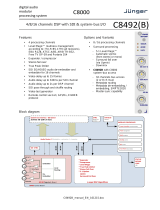
BBG-1022-FS-DSP Functional Description
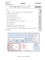
Figure 1-1 shows a functional block diagram of the BBG-1022-FS-DSP. The
BBG-1022-FS-DSP includes AES/analog audio support and CVBS video I/O.
In addition to a basic signal presence input failover function, a Quality Check
option allows failover to alternate inputs or other actions based on
user-configurable criteria such as black or frozen frame. Frame sync and full
up-down-cross conversion can be added as options.
The BBG-1022-FS-DSP provides a DSP-based platform that supports
multiple audio DSP options. When optioned with various diverse audio
processing options, the DSP-based processing core (which supports numerous
simultaneous processing engines) uses license “credits” which allows flexible
tailoring of multiple proc function instances.
Note: The BBG-1022-FS-DSP DSP base adds support for various DSP audio
options. Specific individual DSP user assets (such as loudness processing,
upmixing, and Dolby encoders) are activated for use only when
corresponding option licenses also reside on the device.
BBG-1022-FS-DSP Input/Output Formats
The BBG-1022-FS-DSP provides the following inputs and outputs:
• Inputs:
• 3G/HD/SD SDI IN A thru SDI IN D – four 3G/HD/SD-SDI inputs.
SDI IN A or SDI IN B can be set to failover to A or B in absence of
opposite channel of this pair.
• CVBS IN – CVBS coaxial analog video input.
• AES IN – BNC (AES-3id, 75Ω) ports as AES input (number of
ports dependent on model).
• AN-AUD IN – Four balanced analog audio embed inputs.
• Outputs:
• 3G/HD/SD-SDI OUT (1-4) – four 3G/HD/SD-SDI buffered video
outputs. Each output can be independently set as processed output
video or selected input video reclocked.
• AES OUT – BNC (AES-3id, 75Ω) ports as AES outputs (number of
ports dependent on model).
• AN-AUD OUT – Four balanced analog audio de-embed outputs.
• CVBS OUT – CVBS coaxial analog video usable with SD video
streams.

1 BBG-1022-FS-DSP Functional Description
1-6 BBG-1022-FS-DSP PRODUCT MANUAL BBG-1022-FS-DSP-OM (V1.1)
Figure 1-1 BBG-1022-FS-DSP Functional Block Diagram
EQ/
Reclock
Output
Crosspoint
3G/HD/SD
SDI IN A
BBG-1022-FS-DSPBD V1.0LB144
Deserialize
PROC
VIDEO
OUT
(SDI)
EQ/
Reclock
3G/HD/SD
SDI IN B
Video
ADC
CVBS IN
Input Select/
Failover
GPIO
Control/
Monitor
Selected Input RCK (to
Output Crosspoint)
Timecode
Select/Proc
Video
DAC
CVBS OUT
1
2
3
4
Serialize
AES
Rx
Audio
ADC
AES IN
AN-AUD IN
AES
Tx
Audio
DAC
AES OUT
AN-AUD OUT
Notes: 1. Signal connections shown depicts full input/output capability.
Practical input/output signal availability is determined by model.
Refer to text for more information.
2. Some functions shown here are available only with corresponding
card option(s). Asterisk (*) denotes optional function/feature.
Selected
Input RCK
EQ/
Reclock
3G/HD/SD
SDI IN C
EQ/
Reclock
3G/HD/SD
SDI IN D
Video Quality
Events Check*
From
Output
Crosspoint
Video Proc
Color Corrector*
Framesync/
Pattern Gen
DSP Audio Processing
Audio Routing, Gain Control,
Downmix, SRC, Delay Adj.
Audio DSP Functions*
(Upmixing, Loudness Leveling,
Dolby Encode/Decode)
Ref Loop
Audio
Demux

BBG-1022-FS-DSP-OM (V1.1) BBG-1022-FS-DSP PRODUCT MANUAL 1-7
Introduction BBG-1022-FS-DSP Functional Description
Video Processor Description
The BBG-1022-FS-DSP video subsystem provides the functions described
below.
Input Video Select/Quality Check Functions
A GUI-based control allows the device to select from up to four 3G/HD/
SD-SDI inputs, and a SD CVBS analog video input. For analog inputs,
waveform-based ancillary data is preserved for extraction and usage later in
the device processing chain.
The input can be selected using DashBoard manual control, set to failover to
an alternate input upon loss of the target input, and can be externally selected
via a GPIO interface. An input
Allowed Rasters and Allowed Frame Rates filter
allows inputs to be filtered (screened) for only user-allowed raster sizes and
frame rates, with unallowed raster/rates being rejected as an input (input
unlock). Reclocked copies of any SDI input can be outputted by the device
when selected as a choice on the output crosspoint.
(Option +QC). Quality Check allows criteria such as black/
frozen frame events to propagate an event alert. This alert can be used by the
Event Setup/actions function to invoke video routing changes, GPO, and
other actions.
Video Output Crosspoint
A four-output video matrix crosspoint allows independently applying the
processed video output or reclocked input to any of the four discrete coaxial
outputs (
SDI OUT 1 thru SDI OUT 4). For an SD output, a CVBS coaxial output
is available as a processed video output.
Timecode Processor
(See Figure 1-2.) This function provides for extraction of timecode data from
input video source, and in turn allow individual timecode strings to be
embedded into the output video. The function can monitor any of the video
inputs for supported timecode formats such as ATC_LTC or ATC_VITC for
down-conversions to HD, and ATC_VITC or VITC waveform (with
selectable odd/even field line number control) for SD SDI or CVBS inputs.
Waveform VITC timecode can also be extracted from a reference input and
used as the output timecode value. If the preferred format is detected, the
preferred format is used by the device; if the preferred format is not detected,
the device uses other formats (where available) as desired. An
internally-generated free-run timecode can be also be embedded on output
video if desired.
The function also provides conversion between various timecode formats and
provides independent insertion and line number controls for each SDI
timecode output format.
When licensed with option
+LTC, this function also can
receive, send and translate between audio/RS-485 LTC timecode formats and
the VBI formats described above.

1 BBG-1022-FS-DSP Functional Description
1-8 BBG-1022-FS-DSP PRODUCT MANUAL BBG-1022-FS-DSP-OM (V1.1)
Figure 1-2 Timecode Processor
Frame Sync Function
Option +FS provides for frame sync control using an external looping
reference signal, or the input video as a frame sync reference.
This function also allows horizontal and/or vertical offset to be added
between the output video and the frame sync reference.
Frame sync can select from either the external frame reference source, or
free-run input video sync. Selectable failover allows alternate reference
selection should the initial reference source become unavailable or invalid. In
the event of input video loss of signal, the output can be set to disable video,
go to black, go to an internal test signal generator pattern, or freeze to the last
intact frame (last frame having valid SAV and EAV codes).
An internal test signal generator provides a selection of various standard
patterns such as color bars, sweep patterns, and other technical patterns. The
test patterns can be applied to the output video upon loss of input or manually
inserted at any time.
Frame
Reference
SDI VITC
Waveform
Detect/Extract
SDI ATC_LTC
Detect/Extract
SDI ATC_VITC
Detect/Extract
Priority/
Select
Program
Video
Input
SDI VITC
Timecode
Proc/Embed
ATC_VITC
Timecode
Proc/Embed
ATC_LTC
Timecode
Proc/Embed
Insert
Control
Line
Number
Control
Buffer/
Format
3G/HD/SD–SDI
Free Run
(Internal Count)
Ref VITC
Waveform
Detect/Extract
Audio LTC
Select/Extract
Audio/
RS-485 LTC
Audio/RS-485
LTC Generate
Audio LTC Out
RS-485 LTC Out

BBG-1022-FS-DSP-OM (V1.1) BBG-1022-FS-DSP PRODUCT MANUAL 1-9
Introduction BBG-1022-FS-DSP Functional Description
Video Quality Events Detect Function
Option +QC provides a Video Quality Events user interface and an Event
Triggers
user interface for setting an area of concern across the program raster
which can be monitored for frozen or black video events. Threshold controls
allow setting the sensitivity of the function, while engage and disengage
threshold timing controls allow setting how fast the event detection engages
and releases when triggered. The
Event Triggers user interface allows
instructing the device as to the action to take upon an event (such as go to a
changed signal routing, activate a GPO, send an automated email, or go to a
user-defined preset).
An
Event Triggers user interface can detect Closed Caption Presence and
Closed Caption Absence events. The
Event Triggers user interface in turn
allows instructing the device as to the action to take upon an event (such as go
to a changed signal routing, activate a GPO, send an automated email, or go to
a user-defined preset).
Wings Insertion
Wings insertion allows a symmetrical L-R wings insertion to be integrated
into the program video output. Wings video is accommodated using a
separate wings SDI input. The wings user interface displays wings timing
relative to the output video, allowing wings timing offset to be adjusted such
that wings can be properly framed. (This function does not provide timing
offset control of the wings video; offset must be provided by a external frame
sync card or device controlling the wings video feed.)
The wings L/R insertion width can be manually configured using a wings
width control.
Key/Fill Insertion
Option +KEYER provides for three of the device SDI video inputs to be used
as respective program video, key, and fill inputs. This function provides
chroma keying using the
KEY VID IN signal. The FILL VID IN signal provides
the fill video that is inserted in the area “cleared out” by the key. The keying
user interface displays key and fill timing relative to the output video,
allowing timing offset to be adjusted such that key and fill can be properly
framed. (The option and its host BBG-1022-FS-DSP does not provide timing
offset control of the key/fill video; offset must be provided by external frame
sync cards or devices controlling the key and fill video feed.) The program
video input when using keying accommodates either an SDI or an analog
video input; key and fill inputs are SDI only.
Alpha threshold keyer modes allow full-color key/fill from cost-effective
generic sources such as a standard PC (with appropriate HDMI-to-SDI output
conversion) hosting simple .bmp, .jpeg, or .png graphic files. In these modes,
a common key/fill SDI input provides both the key and fill input.

1 BBG-1022-FS-DSP Functional Description
1-10 BBG-1022-FS-DSP PRODUCT MANUAL BBG-1022-FS-DSP-OM (V1.1)
Color Corrector
Option +COLOR converts the YCbCr SDI input video to the 4:4:4 RGB color
space (where the color correction is applied), and then back to YCbCr SDI on
the output. Controls are available to adjust each RGB level independently for
both white levels (gain) and black levels (offset). Gamma can also be
independently adjusted for each RGB channels. Various controls can be
ganged to provide adjustment for all three color channels simultaneously.
Character Burn-in Functions
User text, video format, and timecode (as selected using the timecode
function) can be burned into the output video. Burn-in attributes such as size,
position, background, color, and opacity are user-configurable. Two discrete
character burn strings can be inserted on output video, with each string
inserted as static text and/or insert only upon LOS. A moving-box insertion
can be enabled to serve as a dynamic raster confidence check even in cases
where the input video image is static or lost.
Trouble Slate Insertion Function
Option +T-SLATE provides for graphic insertion onto the SDI processed
output raster. The function allows for uploading a .png image graphic file to
the card/device memory. (png files are converted to a special format using a
web tool before uploading to the host card/device; this is described in the
setup/operating instructions later in this supplement.)
When the image file(s) is uploaded to the card, its insertion can be enabled via
DashBoard Event Setup controls that enable the graphic insertion only under
certain conditions as desired. (For example, a trouble slate graphic can be set
to insert upon detected input Loss of Signal (LOS).
The trouble slate
function allows for positioning the image within the active
video using DashBoard controls. Refer to +LOGO / +T-SLATE Manual
Supplement OPT-SW-PHXLTS-MS for detailed information and installation/
setup instructions.
Ancillary Data Processor
Option +ANC provides full VANC/HANC ancillary data de-embedding and
embedding for 3G/HD/SD-SDI streams. Direct access to DID and SDID
locations allows extraction or insertion of user data such as camera PTZ,
SCTE 104, closed-captioning read/insert, GPI/GPO via ANC, or other
specialized user payloads. Data can be extracted and inserted within the
device (Bridge mode), or inserted and/or extracted to and from the device via
serial or IP interfaces connecting to external devices/systems.

BBG-1022-FS-DSP-OM (V1.1) BBG-1022-FS-DSP PRODUCT MANUAL 1-11
Introduction BBG-1022-FS-DSP Functional Description
Audio Processor Description
The audio processor operates as an internal audio router. This function
chooses from the following inputs:
• 16 channels of embedded audio from the SDI video input (default
1-to-1 routing to SDI output)
• Up to 16 channels (8 pairs) of discrete AES input
1
• Up to 4 channels of balanced analog audio input
(See Figure 1-3.) The audio processing subsection is built around an internal
16-channel audio bus. This 16-channel bus receives inputs from an input
routing crosspoint that routes de-embedded, and discrete AES and analog
audio inputs, over the 16-channel internal bus. Correspondingly, at the output
end of the 16-channel bus is an output routing crosspoint that in turn
distributes the 16-channel bus signals to embedded, and discrete AES and
analog audio outputs.
An Input Audio Status display shows the presence and peak level of each
input audio channel received by the device. In addition to SDI embedded
audio channel sources, analog and coaxial AES inputs are available as input
audio choices. For AES audio inputs, payload is identified (PCM or data such
as Dolby
®
Digital or E). Each AES input pair has independent sample rate
converters to align each input pair with video timing to accommodate cases
where AES audio is not synchronous with input video (SRC automatically
bypassed for non-PCM payloads). As such, the audio subsection provides a
full crosspoint between all supported audio inputs and output types.
Figure 1-3 Basic Audio Processing Block Diagram
1. Discrete audio I/O channel count is dependent on model. Not all models may support maximum
number of available discrete channels.
De-Embed IN 1-16
(from Program
Video De-Embed)
AES
Rx/SRC
Input Routing
Internal
Bus
Routing/Gain/
Mute/Invert
Controls
Analog
Audio
ADC
Audio
Meters
AES IN
AN-AUD
IN
Audio
Delay
Offset
Control
Internal Bus Controls
Ref
Dolby E
Alignment
Control
Output Routing
Routing/Gain/
Mute/Invert
Controls
Audio
Meters
AES
Tx
Analog
Audio
DAC
AES OUT
AN-AUD
OUT
Embed 1-16
(to Program Video
Embed)
9902AUD V1.0LB89
Downmix

1 BBG-1022-FS-DSP Functional Description
1-12 BBG-1022-FS-DSP PRODUCT MANUAL BBG-1022-FS-DSP-OM (V1.1)
Clean and Quiet Switching option +CQS allows SDI input
selection to be changed from one source to another while ducking audio
during controlled input video switching transitions to provide silence between
input switches. The cross-fade is queued for the next available RP168 switch
line following the switch command.
Note: • Clean audio switching is assured only for intentional, controlled switches via
user control. Clean audio switching cannot be assured for failover switches.
• Clean switching requires that both SDI signals (switch from and switch to)
be stable and present, and of the same SDI format and rate.
• Clean audio switching function is designed for PCM audio. This function
does not assure clean decoded audio when switching from/to Dolby or other
non-PCM audio.
Audio Down Mix Function
(See Figure 1-4.) The Audio Down Mixer function provides for the selection
of any five embedded channels serving as Left (
L), Right (R), Center (C), Left
Surround (
Ls), and Right Surround (Rs) individual signals to be multiplexed
into stereo pair Down Mix Left (
DM-L) and Down Mix Right (DM-R). The
resulting stereo pair
DM-L and DM-R can in turn be routed to any embedded
audio pair as desired (or de-embedded to an AES or analog audio output).
Figure 1-4 Audio Down Mix Functional Block Diagram with Example Sources
Flex Buses
For both input and output nodes before and after the internal buses, flex buses
provide flexible-structure mixer in which any of 16 summing nodes (
Flex Mix
Bus A
thru Flex Mix Bus P) can receive any device audio input, thereby
allowing several customizable mixing schemes. Similarly, any of the 16
internal bus signals can be applied to an output flex bus mixer.
Audio DSP Function
The Audio DSP Function provides a DSP-based platform that supports
multiple audio DSP options. When optioned with various diverse audio
processing options, the DSP-based processing core (which supports numerous
simultaneous processing engines) uses license “credits” which allows flexible
tailoring of multiple proc function instances. Audio proc options include
Dolby
®
Real-Time Loudness Leveling automatic loudness processing,
Dolby
®
D/D+ encode/decode, and Linear Acoustic
®
UPMAX™ automatic
upmixing.
DM-L
L
R
C
Ls
Rs
DM-R
Emb Ch 1
Emb Ch 2
Emb Ch 3
Emb Ch 5
Emb Ch 6
Embed Ch 1 - Ch 16

BBG-1022-FS-DSP-OM (V1.1) BBG-1022-FS-DSP PRODUCT MANUAL 1-13
Introduction BBG-1022-FS-DSP Functional Description
(See Figure 1-5) The Audio DSP block is positioned between all device audio
inputs (input mixer positioning) as well as audio outputs (output mixer
positioning). Actual audio DSP proc functions are facilitated using licenses
for these options. When any audio option is licensed (activated), the
processing can be positioned at the input or output mixer as desired.
• Input Mixer path positioning locates the DSP pipeline to receive basic
external inputs coming into the device, and then allows DSP
processed output channels to be directed to the internal Audio Bus
channels by selecting Audio DSP channels as sources for destination
Audio Bus channels via the Input Audio Routing/Controls
• Output Mixer path positioning locates the DSP pipeline to receive
Audio Bus channels and then place the DSP processed output
channels directly at the device audio outputs as sources for
destination Embedded Output or AES Output channels via the Output
Audio Routing/Controls.
Figure 1-5 DSP Pipelines and Input/Output Mixer Positioning
+DSP Options. Option licenses provide the user-exposed DSP
functions. Available DSP options are as follows. Multiple licenses for the
same or different options can be installed and used simultaneously.
• +DSP-RTLL-5.1 Dolby
®
Real-Time Loudness Leveling™
5.1-Channel Loudness Processor Option
• +DSP-RTLL-2.0 Dolby
®
Real-Time Loudness Leveling™
2.0-Channel Loudness Processor Option
Both
DSP-RTLL-5.1 and DSP-RTLL-2.0 provide for specially suited
Target Level (which sets the target loudness level) as desired. A Peak
Limit function can be set to provide absolute peak limiting. This
function is also configurable for aggressiveness. An intelligent
Speech Percentage detection algorithm can help distinguish between
program speech and other sounds. This can help in “fine tuning”
various parameters to best suit the program material.
DSP A/B•
•
•
Emb 1-16
•
•
•
AES 1-16
Etc.
Audio Bus
Channels 1-16
•
•
•
Emb Out 1-16
AES Out 1-16
Audio Bus
Channels 1-16
DSP C/D
DSP E/F
DSP G/H
DSP A/B
DSP C/D
DSP E/F
DSP G/H
Input Mixer DSP Positioning Output Mixer DSP Positioning

1 BBG-1022-FS-DSP Functional Description
1-14 BBG-1022-FS-DSP PRODUCT MANUAL BBG-1022-FS-DSP-OM (V1.1)
• +DSP-ENCD-5.1 Dolby
®
Digital/Digital Plus 5.1 Encoder
• +DSP-ENCD-2.0 Dolby
®
Digital/Digital Plus 2.0 Encoder
• +DSP-DEC Dolby
®
Decoder
• +DSP-UPMIX-LA Linear Acoustic
®
UPMAX™ 2.0-to-5.1 Upmixer
Chapter 3 – Operating Instructions shows various examples of setting up and
using the Audio DSP Proc functions.
Text-To-Speech
Cobalt Digital +TTS is a complete 21CVAA digital text-to-speech generation /
audio insertion solution for embedded and discrete audio systems.
+TTS is
available as a software option for new BBG-1022-FS-DSP units. For field
upgrade, the unit must be returned to the factory for option installation.
+TTS interfaces with industry standard Windows Share folder systems to
receive non-proprietary text, XML, or similar plain text files, and converts
and inserts realistic human-voice audio into user-configured audio channels
(typically an SAP channel pair intended for this playout).
+TTS allows for
prioritization based on the organization's discretion (for example, severe
weather alerts out-prioritizing school closings). Alert tones are inserted over
the main program channels to alert the visually impaired that emergency
content is to occur on the SAP channel. Alerts can be played a configurable
number of times, and alerts with higher priority can interrupt current lists for
breaking news. Once the interrupt message is broadcast,
+TTS automatically
reverts to normal audio programming. Refer to +TTS Manual Supplement
OPT-TTS-MS for detailed information and installation/setup instructions.
EAS Text Crawl Generation Option +EAS provides for
automated keying Emergency Alert System (EAS) text crawls in the active
program video output. The function receives its text stream via a device serial
data input. The EAS crawl start can be set to trigger upon receiving the serial
data message, or be set to use a GPI to trigger start of the EAS crawl.
Embedded in the received serial data are commands which set the message
severity to be shown by the keyed crawl (severity is correlated to
user-specified text color and background color for the crawl). User controls
allow control of the crawl speed and repeat of the crawl burn-in (if desired).
Refer to +EAS Manual Supplement OPT-SW-PHXEAS-MS for detailed
information and installation/setup instructions. This supplement is available
as a download on the Products Download page/tab on the product web page.
Audio Events Detect Function
Option +QC provides a Audio Detect Events user interface and an Event
Triggers
user interface for checking user-selected channels to detect audio
silence conditions. The
Event Triggers user interface in turn allows instructing
the device as to the action to take upon an event (such as go to a changed
signal routing, activate a GPO, send an automated email, or go to a
user-defined preset).

BBG-1022-FS-DSP-OM (V1.1) BBG-1022-FS-DSP PRODUCT MANUAL 1-15
Introduction BBG-1022-FS-DSP Functional Description
Control and Data Input/Output Interfaces
GPI Interface
Two independent ground-closure sensing GPI inputs (GPI 1 and GPI 2; each
sharing common ground connection as chassis potential) are available.
Associated with each GPI user control is a selection of one of 32 user-defined
presets in which GPI activation invokes a control preset.
Because the GPI closure invokes a user-defined preset, the resulting setup is
highly flexible and totally user-defined. Invoking a user preset to effect a
change involves device setup communication limited only to the items being
changed.
GPI triggering can be user selected to consider the activity on discrete GPI
ports, or combinations of logic states considering both GPI inputs, as well as
be set for level or edge triggering. This flexibility allows multistage,
progressive actions to be invoked if desired. Indication is provided showing
whenever a GPI input has been invoked.
GPO Interface
Two independent phototransistor non-referenced (floating) contact pairs
(
GPO 1/1 and GPO 2/2) are available. A GPO can be invoked by setting a GPO
to be enabled when a preset is in turn applied (i.e., when a preset is invoked
(either manually or via event-based loading), the GPO is correspondingly also
activated.
Serial (COMM) Ports
The BBG-1022-FS-DSP is equipped with two, 3-wire serial ports (COM 1 -
Serial Port 1, COM 2 - Serial Port 2). The ports provide for SMPTE 2020
de-embedding to an output port, and provide RS-485 LTC I/O (when licensed
with option
+LTC). Either port can be configured as RS-232 Tx/Rx or RS-422
non-duplexed Tx or Rx.
+SCTE104 Insertion
Option +SCTE104 provides generation and insertion of SCTE 104 messages
into baseband SDI. Message send can be triggered from automation GPI or
other event action modes. The option can also execute actions based on SCTE
104 messages received by the device, as well as send triggered SCTE 104
packets to other downstream systems.
The user interface is based on common SCTE 104 operations: Splice Start
Normal, Splice Start Intermediate, Splice End Normal, Splice End
Intermediate, and Splice Cancel (splice_request_data variants), offering full
control of splice start, end, and cancel as well as pre-roll and break duration
offsets. (A Manual Supplement is planned for this option. Please check
product web page.)

1 Technical Specifications
1-16 BBG-1022-FS-DSP PRODUCT MANUAL BBG-1022-FS-DSP-OM (V1.1)
Alarm Function
The device can be set to monitor input video/audio for input errors such as
input LOS, frozen or black frame, loss of reference, closed captioning
ancillary data loss, and/or per-channel audio absences. These alarms can be
propagated as a device general error or warning message, and can be
downloaded as basic .txt logs or via a Syslog function.
User setup tables configure the alarm severity escalation as well as trigger
holdoff/release and other thresholds as applicable.
User Control Interface
BBG-1022-FS-DSP uses an HTML5 internal web server for control/
monitoring communication, which allows control via a web interface with no
special or unique application on the client device. Connection to the device to
the network media connection is via a standard 10/100/1000 RJ-45 Ethernet
connection. The device can also be controlled using DashBoard™ remote
control, where it appears as a frame connection.
Technical Specifications
Table 1-1 lists the technical specifications for the BBG-1022-FS-DSP 3G/
HD/SD-SDI Standalone Frame Sync with Audio/Video Processing, DSP
Audio Support, Audio Embedding/De-Embedding, and CVBS I/O unit.
Table 1-1 Technical Specifications
Item Characteristic
Part number, nomenclature • BBG-1022-FS-DSP 3G/HD/SD-SDI Standalone Frame Sync with
Audio/Video Processing, DSP Audio Support, Audio Embedding/
De-Embedding, and CVBS I/O, available in the following
rear-panel I/O configurations:
- BBG-1022-FS-DSP-B (4) 3G/HD/SD-SDI Input BNCs,
(4) 3G/HD/SD-SDI Output BNCs, (1) 3G/HD/SDI Output BNC
(with relay bypass failover), (1) GPIO/COMM RJ-45 connector
- BBG-1022-FS-DSP-C (1) 3G/HD/SD-SDI Input BNC,
(1) CVBS Video In BNC, (2) AES In BNCs, (2) Balanced Analog
Audio Inputs, (1) 3G/HD/SDI Output BNC, (1) CVBS Video Out
BNC), (2) AES Out BNCs, (2) Balanced Analog Audio Outputs
- BBG-1022-FS-DSP-D-DIN (4) 3G/HD/SD-SDI Inputs,
(2) Balanced Analog Audio In, (6) AES Inputs, (4) 3G/HD/SDI
Outputs w/ (1) relay protect, (4) AES Outputs, GPIO/COMM
(RJ-45 connector). (All coaxial connectors DIN 1.0/2.3)
- BBG-1022-FS-DSP-D-HDBNC (4) 3G/HD/SD-SDI Inputs,
(2) Balanced Analog Audio In, (6) AES Inputs, (4) 3G/HD/SDI
Outputs w/ (1) relay protect, (4) AES Outputs, GPIO/COMM
(RJ-45 connector). (All coaxial connectors HD-BNC)
/