CONFIGURATION
The Zone Module has a number of parameters that have to be configured. As indicated before, the Zone
Module requires the use of a Touch Thermostat to proceed to its configuration.
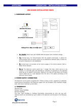
This is a list of the parameters, its description and ranges of selection.
Paramete
Description
alue
=&2Q
Configuration of Zone Module
0$6:Master
6XE: Subordinate
=&LG
Zone Module ID (the address of the
Zone Module)
If Master : 1 to 8
If Subordinate : 9 to 32
SHU&
Zone weight Percentage 10% to 100%
W&L'
Thermostat Controller ID
Range defined by the number of Master Zone
Modules
]&S&
Zone Module Probe Configuration
2II: default value
USW: measurement by a remote temperature
sensor
=&6,
Zone Module Sleep Input (motion
detector)
2II: default value
12: activates when closing the circuit
Q&: activates when opening the circuit
=&U,
Zone Module Remote Input (door
or window contact)
2II: default value
12: activates when closing the circuit
Q&: activates when opening the circuit
6EGW
Stand By Display Temperature
$W: ambient temperature
6W: set point temperature
2)6W
Offset (adjust the zone temperature
reading)
-5ºF to 5ºF
]&I9
Zone Module Firmware Version
=WI9
Zone Thermostat Firmware Version
6&I9
System Controller Firmware
Version (Airzone Controller)
CONNECTION
Here are the steps we suggest you for a clean, fast and easy installation.
1) Have a lay out drawing of the house, and locate where each thermostat and each damper will be
installed and define the address each module will be assigned, and how the communications wire
will be layered out. Keep that document in your records for future maintenance.
2) Install all dampers according with your design and where the customer wants to have controlled
airflow. Be sure that the dampers are in good condition (not deformed). Install the dampers
according with the local building recommendations. Be sure that this two conditions are followed:
a) Mount the damper in such way that the motor is accessible
b) Be sure that the damper will be accessible for service.
3) If a bypass is required for this installation, install it now.
4) Lay out the communication cable and attach the cables to the connectors as indicated in the Training
Manual.
5) Install the Airzone Controller and the 12VDC power supply in their DIN rail, near the air handler unit.
6) Power on the Airzone Controller, and verify that the power LED is ON
7) Disconnect the DC power from the Airzone controller.
8) Connect all the modules to the bus, thermostat and damper motor cables, but do not connect the
thermostats.
9) Power on the Airzone Controller.
10) Verify that there are 3 VDC between the contacts + and – of the thermostat bases.
11) Install the thermostats in their bases
12) Proceed to the initial configuration for all master modules connected to the thermostats.
13) Using the Installation thermostat, proceed to the initial configuration of all subordinate modules.
14) Configure any additional module parameter if required (remote temperature sensor, door contact,
motion contact, etc)
15) Save the configuration in the Airzone Controller. (please, follow the procedure explained in the
Training Manual).
16) Cycle the power in the Airzone Controller.
17) All dampers should be open.
18) Install the J2 jumper in the Airzone controller
19) Install the iQdrive
20) Proceed to install the iQ thermostat as indicated in its manual
21) Connect the iQ bus in the Air handler unit to the Airzone Controller (please, see both Training
Manuals)
22) Verify that the iQ thermostat shows under the current mode, “Zone Control”.
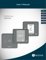
Description Corrective action
(UURU
Description Corrective action
(UU
Local communication
error
Check the connections and wiring between
the zone control and the thermostat
(UU
Damper
blocked
Check that the zone control’s connection to the
motorized system has not shorted out.
Check that the motorized system is not blocked.
(UU
Bus communications
error
Check the zone control’s connection to the
bus.
(UU
No zone
control sensor
Check that the circuit of the sensor connected to
the zone control (if any) is not open.
Check the configuration of the “
” parameter.
(UU
Damper not connected
Check the zone control’s connection to the
motorized system.
Check that the motorized system is not free.
(UU
Zone-control
sensor short-
circuit
Check that the circuit of the sensor connected to
the zone control (if any) has not shorted out.
Check the configuration of the “
” parameter.