Broan PSA4BI Installation guide

Category
Thermostats
Type
Installation guide

This manual is also suitable for

Installation Instructions
Split System Air Conditioner
The iQ Drive
®
air conditioner operates as part of a larger intercommunicating system which provides temperature, air fl ow,
and humidity control for a residence or other similarly sized building. This system includes this outdoor unit, the dedicated
iQ controller (thermostat), and an iQ system-compatible indoor unit, typically an air handler with electric strip heat or a
gas furnace. The system will function only if these components are matched and intended for use within this system. A
complete list of compatible equipment by model and serial number is available in NORDYNE document 709031, iQ Field
Wiring Installation Instruction. Accessory equipment which may be used with this system includes humidifi ers, electric or
electronic air cleaners, and U/V (ultraviolet) sterilizing lamps.
Refer to the System Operation section below for a complete description of how to use the various features of the system.
In addition to providing the means for operation, the controller also serves as the means for initial system confi guration and
setup, and it provides a considerable amount of information for troubleshooting the system and diagnosing problems.
OTHER REFERENCE DOCUMENTS
Installation instruction documents for indoor equipment (furnace or air handler, optional humidifi er, etc.)
iQ Field Wiring Installation Instruction, document 709031, provided in the iQ thermostat/controller kit
iQ Thermostat/Controller User’s Manual, document 709063, provided in the iQ thermostat/controller kit
local wiring and building codes
Nordyne Application Guideline for Refrigerant Lines Over 75 Feet document 044B-0600
iQ Zone System Zone Thermostat User’s Manual
iQ Zone System Installation Instructions
2
TABLE OF CONTENTS
PREPARATION ....................................................................................................................................................3
Slab Mounting ..................................................................................................................................................3
Roof Mounting ..................................................................................................................................................3
ELECTRICAL CONNECTIONS ...........................................................................................................................3
Electrical Power Wiring ....................................................................................................................................3
Control Circuit Wiring .......................................................................................................................................4
iQ Zone Control Wiring ....................................................................................................................................4
Recheck Wiring ................................................................................................................................................4
REFRIGERANT LINE CONNECTIONS ...............................................................................................................4
Line Design and Routing ..................................................................................................................................4
Brazing .............................................................................................................................................................5
System Evacuation ..........................................................................................................................................5
Refrigerant Charging ........................................................................................................................................5
Alternate Procedure for Refrigerant Charging Based on Subcooling ..............................................................6
SYSTEM SETUP USING THE IQ CONTROLLER ...............................................................................................6
General ............................................................................................................................................................6
Screen Navigation ............................................................................................................................................6
The Main Screen ..............................................................................................................................................6
Installer Settings ..............................................................................................................................................7
System Confi guration ..................................................................................................................................7
Accessories .................................................................................................................................................7
Dealer Information .......................................................................................................................................8
Heat Off Delay .............................................................................................................................................8
Altitude Adjust .............................................................................................................................................8
Service Tests ...............................................................................................................................................8
SERVICE INFORMATION SCREENS .................................................................................................................9
Other Confi guration Entries ........................................................................................................................... 10
Auto Changeover Time .............................................................................................................................. 10
Date and Time ........................................................................................................................................... 11
Program Schedule vs. Nonprogrammable ................................................................................................. 11
Dehumidifi cation ........................................................................................................................................ 11
Humidity Settings ...................................................................................................................................... 11
Smart Recovery ........................................................................................................................................ 12
Zone Control .............................................................................................................................................. 12
System Operation: Quick Start....................................................................................................................... 13
System Startup, Checkout, & Troubleshooting ............................................................................................... 13
SYSTEM DIAGNOSIS & TROUBLESHOOTING ............................................................................................... 14
Controller ....................................................................................................................................................... 14
Outdoor Unit Inverter ..................................................................................................................................... 14
Indoor Unit Interface Board ............................................................................................................................ 15
Indoor Unit EXV Board (at the indoor coil, furnace or air handler)................................................................. 15
Indoor Unit Constant CFM Motor Control Board ............................................................................................ 15
Indoor Unit One or Two-Stage G7 Furnace Board ......................................................................................... 15
Indoor Unit iQ Modulating Gas Furnace Board .............................................................................................. 15
Airzone Control Board .................................................................................................................................... 15
iQ Zone System Confi guration ....................................................................................................................... 16
Common Troubleshooting Issues ................................................................................................................... 16
MAINTENANCE ................................................................................................................................................. 16
FIGURES & DIAGRAMS .................................................................................................................................... 17
3
PREPARATION
Before proceeding with installation of iQ Drive® air conditioner
equipment, consult with the distributor and homeowner to
confi rm that the equipment listed on the order is what was
ordered, and that it matches labeling on the equipment
packaging.
Next determine (including consultation with the homeowner) the
intended/preferred location for placement of the compressor/
outdoor coil unit. Unit envelope dimensions are shown in
Figure 1.
This air conditioning unit is designed for outdoor installation
only. Unit placement must take into consideration the following
clearances: (a) A minimum of 18 inches must be provided
between each of the four sides and any solid barrier or wall
which might block free inlet air fl ow into the coil. A minimum
clearance of 36 inches is required between multiple units.
(b) The corner of the unit covered by the control access
cover must be clear enough to allow comfortable access by
a serviceperson. (c) The top of the unit must be open and
unobstructed to prevent recirculation of outdoor fan discharge
air, particularly for air conditioning usage. A minimum distance
of 4 feet overhead clearance is recommended. Do not locate
the unit in a pit with high walls on all sides.
Locate the unit away from overhangs which would allow water
runoff or ice to fall directly onto it. Avoid placing the condensing
unit near sleeping quarters or windows.
Slab Mounting
The preferred unit mounting is on an outdoor slab (concrete or
plastic), on the ground, in an area with good drainage unlikely
to be affected by heavy runoff or ground settling. The support
slab should be level. Make sure that the drain holes in the
bottom of the unit are not obstructed.
Roof Mounting
The method used for roof mounting should be designed so
as not to overload roof structures nor transmit noise to the
interior of the structure. Refrigerant and electrical lines should
be routed through suitably waterproofed openings to prevent
leaking into the structure. Make sure that the roof structure
can adequately support the weight of the equipment. Consult
local building codes for rooftop installations.
After a location has tentatively been selected, trace routing
of new (or pre-existing) refrigerant lines (two), and power and
control wiring. See further discussion below.
Maximum recommended length for refrigerant lines: 100 ft.
Maximum elevation difference, compressor base to indoor
coil base (compressor higher): 50 feet NOTE: An oil trap
is required for elevations exceeding 50 feet.
Maximum elevation difference, compressor base to indoor
coil base (compressor lower): 50 feet NOTE: An oil trap is
required for elevations exceeding 50 feet.
Refrigerant lines should NOT be buried. (in concrete or
otherwise)
Refer to Nordyne Application Guideline for Refrigerant Lines
Over 75 Feet document 044B-0600, for piping details
After the above information has been confi rmed and potential
questions regarding location, refrigerant line routing, and
wire routing have been resolved, proceed with unpacking the
equipment. It is strongly recommended that inspection of the
hardware be performed prior to bringing it to the installation
site. Inspect for cosmetic as well as functional damage (such
as obvious holes or gaps in tubes and joints, cut or pinched
wires or wire insulation).
Verify that the iQ Drive
®
air conditioning unit package includes
the following:
• Coil/compressor/control unit.
Packet containing installation instructions and one fi lter-drier.
NOTE: The thermostat/controller which is required for system
operation is part of a separately purchased kit.
ELECTRICAL CONNECTIONS
WARNING:
ELECTRIC SHOCK HAZARD
Disconnect all electrical power at main circuit box
before wiring electrical power to the outdoor unit.
Failure to follow these instructions may result in
electric shock or death.
Electrical Power Wiring
Electrical power wiring shall comply with the current
provisions of the National Electrical Code (ANSI/NFPA 70)
as supplemented by applicable local building codes. The
installer should become familiar with the wiring diagram
before making electrical connections to the outdoor unit. An
equipment wiring diagram is included in this instruction and
inside the unit control panel cover. Refer to the unit rating label
located on the exterior of the control box cover for operating
voltage, minimum circuit ampacity, and maximum fuse size.
See Table I for wire sizing.
COPPER WIRE SIZE - AWG (1% Voltage Drop)
Supply Circuit Ampacity
Supply Wire Length - Ft
up to 50 51 - 100 101 - 150 151 - 200
15 14 10 8 6
20 12 8 6 4
25 10 8 6 4
30 10 6 4 4
35 8 6 4 3
40 8 6 4 3
45 6 4 3 2
50 6 4 3 2
Wire Sized based on N.E.C. for 60°C type copper conductors
Table 1. Copper Wire Ampacity Tables
A properly sized branch circuit and disconnect switch must
be installed where it is easily accessible and within line of
sight of the outdoor unit.
Remove the control panel cover. Route the power and ground
wires (3 wires, including earth ground) from the disconnect
box to the unit. Use of outdoor shielded conduit (metal
4
lined Sealtite
®
) is required. The electrical conduit opening
is located on the lower left corner of the control box.
Connect the power wires to L1 and L2 box lugs of the
contactor, and the ground wire to the grounding lug to the
left of the contactor. See Figures 2 and 3. Only copper wires
should be used.
Replace the control panel cover before applying power.
Control Circuit Wiring
The air conditioning unit is designed to operate with a 24 VAC
Class II control circuit. Control circuit wiring must comply with
the latest version of the National Electrical Code (ANSI/NFPA
70) as supplemented by local building codes.
In general, 24 VAC control power and communication bus
wiring must be run to interconnect the thermostat/controller,
the indoor unit, and the outdoor unit. The “hub” of this network
and source of the 24 VAC is located within the indoor unit (air
handler or furnace). Refer to iQ Drive
®
System Field Wiring
Instructions, NORDYNE document 709031 shipped with the
controller, for connection of control wires to the indoor unit
and for description of other indoor fi eld wiring, including to
the controller.
Five (5) wires must be run between the indoor unit and the
outdoor unit (2 for 24 VAC power and 3 for communications).
Use one shielded cable (3 or more conductors) for
communications only, and a separate cable or pair of wires for
control power. Refer to wiring diagram Figure 4 and Table II.
1. Pass the 5 control wires into the hole in the lower right side
of the control panel of the outdoor unit, into the separate
low voltage wiring compartment. See Figures 5 and 6.
2. Locate the 5 corresponding factory-wired leads with
stripped ends. Assure that each of these 5 wires (on the
factory wiring side of the wire connections) loops around
and through the “donut” (toroidal choke). Refer to Figure
7 which shows one wire making a single loop.
3. Connect each of the 5 fi eld-run wires to its factory-wired
counterpart using a wire nut, as indicated in Figures 4, 5
and 6.
4. Replace the control panel cover before applying power.
IMPORTANT
Trace the factory-installed red wire to determine
which wire color scheme shown in Figure 6 matches
the unit. The wires reserved for 24 volt control power
are either GRY and RED in units made starting mid-
2009, or BLK and YEL with black stripes in units
made prior to mid-2009.
It is critical that the wires meant to connect to 24
vac control power are not mistakenly connected to
the communication bus wires. 24 volts applied to
the communication bus will damage the equipment.
Communication Wiring
Interface
Board
Terminal
Interface Board
plug wire color
Outdoor unit wire color
Inverter
terminal
DX+
YEL
(or RED*)
YEL
(or RED*)
DX+
DX- WHT WHT DX-
GND GRN GRN GNDA
Control Power Wiring
R (screw) [no factory wire]
RED
(or BLK-striped YEL*)
(to High Pressure
Switch)
C (screw) [no factory wire]
GRY
(or BLK *)
(contactor coil)
* on earlier iQ A/C units
Table 2. Control Wiring to Outdoor iQ A/C Unit
iQ Zone Control Wiring
For iQ Zone systems, fi eld wiring is required to connect the
Airzone control board to the iQ communication bus and to
provide a ground connection for the separate zoning control
and communication network. Refer to the iQ Field Wiring
Instruction document provided in the iQ controller kit for more
details. A 3-wire cable must be run from a splice point in the
iQ communication bus to the one 3-pin connector on the
Airzone control board.
Recheck Wiring
Check that wire routing is correct and connections are secure
for all power and control wiring.
REFRIGERANT LINE CONNECTIONS
Line Design and Routing
Refrigerant lines must be connected by a licensed EPA certifi ed
technician following sound established installation practice.
After the condensing unit location has been determined and
the unit set in place the refrigerant lines should be routed
and connected.
Refrigerant lines should follow a direct path from the indoor
coil to the outdoor unit avoiding sharp bends. When lines
pass through walls, make sure to properly seal and support
them so that vibration is not transmitted to the structure.
Refrigerant tubing should be supported in a manner which
assures that the tubing will not vibrate or wear as a result
of contact with sharp materials or edges during system
operation.
Lines must be clean refrigeration-grade copper.
• Avoid removing caps and plugs from the condensing unit
or lines until they are ready to be connected.
Insulate the vapor line with refrigerant line insulation ¼” wall
thickness or greater.
Proper system performance and oil management depend on
properly selecting the liquid and vapor line sizes. Refer to Table
III for the proper size of fi eld supplied lines. The maximum
allowable refrigerant line length is 100 ft.
5
Vapor Line
Liquid
Line
Line Set
Length
up to 24 ft. 25 to 39 ft. 40 to 75 ft.
75 to 100
ft.
up to 100
ft.
-024K Units
3/4 in.
(19 mm)
3/4 in.
(19 mm)
7/8 in.
(22 mm)
1 1/8 in.
(29 mm)
3/8 in.
(10 mm)
-036K Units
7/8 in.
(22 mm)
7/8 in.
(22 mm)
1 1/8 in.
(29 mm)
1 1/8 in.
(29 mm)
3/8 in.
(10 mm)
-048K Units
7/8 in.
(22 mm)
1 1/8 in.
(29 mm)
1 1/8 in.
(29 mm)
1 1/8 in.
(29 mm)
3/8 in.
(10 mm)
Table 3. Permissible Refrigerant Line Sizes
The maximum vertical elevation between the condensing unit
and indoor coil is 50 ft. Systems that require more elevation
will need to have an oil trap installed in the vapor line. Refer
to Nordyne Application Guideline for Refrigerant Lines Over
75 Feet (document 044B-0600) for piping details.
A fi lter drier is supplied with the unit. It is required and
recommended that it be installed near the indoor coil.
It is recommended to replace existing refrigerant lines that
were previously used for an R-22 system. If the lines are not
replaced, they must be properly fl ushed by a licensed EPA
certifi ed technician in accordance with the manufacturer’s
instructions and established procedures.
Brazing
Use the appropriate safety equipment while brazing. Items
such as gloves, safety glasses, proper ventilation, and a fi re
extinguisher should be used.
1. Route the refrigerant lines from the indoor coil to the service
valves on the outdoor unit. Avoid sharp radius bends and
turns.
2. Make sure that the vapor line is properly insulated for the
entire length of the run for maximum system effi ciency.
Improper insulation may also create condensation and result
in water damage to the equipment and building structure.
3. Remove the valve cores from the unit’s service valves.
Wrap the valves completely with wet rags to protect them
from overheating during the brazing operation.
4. Connect both the vapor and liquid lines. Tubes should be
round, de-burred and free of debris. Use a phosphorous
and copper or silver brazing alloy for the joints. Do not use
soft solder with a low melting point.
5. Connect the indoor lines according to the indoor unit
instructions. The indoor coil will require the same alloys
and wet rags to protect the sensors from excessive heat
on the refrigerant lines.
6. Allow the service valves to cool and replace the valve cores.
7. Leak test the connections using low pressure dry nitrogen.
System Evacuation
1. Connect the refrigerant gauge manifold to both the vapor
and liquid service valves. See Figure 8. Connect the center
port to the vacuum pump.
2. Open both manifold valves and start the vacuum pump.
After a short time, it is recommended to close the manifold
valves and stop the vacuum pump to look for a rapid loss
of vacuum. Loss of vacuum indicates that there is a leak
in the system. Repeat the leak test if required.
3. Evacuate the system to at least 500 microns to remove
non-condensables and water vapor. Close the manifold
valves and remove the vacuum pump.
4. Connect the refrigerant tank to the center manifold port of
the gauge set. Pressurize the system enough to break the
vacuum.
5. Open both service valves by turning the valve stems ¼
turn counterclockwise. The stem will be in line with the
tubes. Replace the stem caps and tighten. Proceed with
Refrigerant Charging section.
Refrigerant Charging
WARNING:
The air conditioning system contains liquid and
gaseous refrigerant under pressure. Adjustment
of refrigerant charge should only be done by a
qualifi ed, EPA certifi ed technician thoroughly
familiar with this type of equipment. Under no
circumstances should the homeowner attempt to
install and/or service this equipment. Failure to
comply with this warning could result in equipment
damage, personal injury, or death.
NOTES:
The unit must be charged at a fi xed speed setting. For
this purpose the thermostat/controller needs to be wired
and powered prior to charging. Using the thermostat, go
to CHARGE MODE under SERVICE TESTS from the
INSTALLER SETTINGS menu, described later in this
document. Select CHARGE MODE to add or verify system
charge. In the CHARGE MODE screen, COOLING mode
must be selected.
The condensing unit is factory charged for fi eld installed
lines 15 ft. in length with the matching indoor equipment.
Adjustments to the refrigerant charge will be required for
other length and tube sizes. For lines longer than 15 ft with
a 3/8” OD liquid line, add 0.52 oz. per ft.
Small variations in the temperatures and pressures are
normal due to differences in the installation.
Large variations in the temperatures and pressures
could indicate incorrect charge or another problem with a
component in the system.
MODEL:
2 TON
(-024K)
3 TON
(-036K)
4 TON
(-048K)
Factory Charge
(for 15 ft. line set)
10.0 lbs
(160 oz)
10.5 lbs
(168 oz)
11.8 lbs
(188 oz)
Additional Charge
for 50 ft. line set
+ 1.1 lbs
(18 oz)
+ 1.1 lbs
(18 oz)
+ 1.1 lbs
(18 oz)
Additional Charge
for 100 ft. line set
+ 2.8 lbs
(44 oz)
+ 2.8 lbs
(44 oz)
+ 2.8 lbs
(44 oz)
Table 4. Refrigerant Charge Quantities
6
The preferred method of charging is by weighing in the
additional refrigerant required. If a charging scale is not
available, the next preferred charging method would be to
use the sub-cooling method in cooling mode.
Alternate Procedure for Refrigerant Charging
Based on Subcooling:
While charging based on weight is preferred, this method is
acceptable. Use this method when the outdoor temperature
is 60°F or higher to verify the correct charge in cooling mode.
The indoor temperature should be between 70°F and 80°F.
1. Connect the gauge manifold to the liquid and vapor service
valves (Figure 8).
2. Start the system in CHARGE MODE, COOLING. Allow
the system to run 15 minutes to stabilize.
3. Record the liquid refrigerant pressure in psig at the service
valve.
4. Record the liquid refrigerant temperature in °F at the service
valve.
5. Using the temperature value recorded, determine the
corresponding liquid refrigerant pressure from the upper
curve (for cooling) in the charging chart (Figure 9).
6. If the pressure measured in step 3 is less than the required
liquid refrigerant pressure determined in step 5, then
refrigerant needs to be added.
7. If the pressure measured in step 3 is greater than the
required liquid refrigerant pressure determined in step 5,
then the system is over-charged.
8. Add or remove charge from the system depending on the
measurements recorded. Allow the system to stabilize for
15 minutes before taking the next readings.
SYSTEM SETUP USING THE IQ CONTROLLER
IMPORTANT:
It essential that the wires meant to provide 24 volts
to the outdoor unit are not mistakenly connected to
the communication terminals. Check again before
you apply power!
General
Power up the entire system with the iQ controller (thermostat)
installed in its base. The controller will be of use to the installer
for the following general purposes:
Confi guring the system using INSTALLER SETTINGS
screens (required)
Running system service tests (recommended)
Using service information screens to examine and diagnose
system operation (very helpful, if needed)
• Setting options and features which are not typically used
or understood by the homeowner (recommended)
Setting options and features with the homeowner’s oversight
in an effort to train him/her (suggested)
The following descriptions of the controller apply specifi cally to
software Version 5.0. Menu structure and available options will
be different for earlier versions. A summary of the full controller
menu structure is provided in Figures 10 and 11. Some
screens or menu items shown are applicable to heat pump
systems and will not appear with the air conditioning system.
NOTE: This guideline is not intended to be a comprehensive
substitute for proper iQ Drive
®
system training (required).
Screen Navigation
Moving between option categories on menu screens or moving
between possible values for any one option is done using
the and keys. The line or value with a dark background
behind the characters is considered “selected”. To change a
selected option in most screens, or to save a changed value,
use the
key. Use the key to back up into the previous
screen in the menu/screen structure.
The Main Screen
The Main Screen is the normal display viewed on the controller.
It prominently shows room temperature and operating mode
(e.g., COOL or HEAT) in large numerals and letters. Across
the bottom line of the display are fi ve words or abbreviations
(normally RH TEMP MODE FAN MENU) which represent
selectable entry points into the menus. The user can always
return to the main screen from any other screen by repeatedly
pressing the
key.
76°
HUMIDITY
36
HEAT
FAN AUTO
MODE
RH
FAN
TEMP
3/13/09
12:18 PM
OUTDOOR
70
HEAT 62
COOL 85
MENU
For iQ Zone systems with zone control enabled, the Main
Screen will appear slightly different, as shown below. The
local temperature reading is absent, and ZONE CNTL appears
under the operating mode.
HUMIDITY
36
COOL
FAN AUTO
MODE
MENU
FAN
RH TEMP
1/19/09
10:00 AM
OUTDOOR
46
ZONE CNTL
7
Installer Settings
Using procedures explained in iQ Drive
®
training, go to the
INSTALLER SETTINGS menu screen.
INSTALLER SETTINGS
SYSTEM CONFIGURATION
RESTORE DEFAULTS
DEALER INFORMATION
ALTITUDE ADJUST


ACCESSORIES
SERVICE TESTS
HEAT OFF DELAY
IQ DRIVE REV 5.0
Other than in the splash screen displayed when power is fi rst
applied to the controller, this is the only screen which displays
the controller software version number.
NOTE: It is important that any settings or service tests which
are appropriate be made at the time of system installation.
System Confi guration
Any time “CONFIGURATION NEEDED” appears at the top of
the Main Screen, the user must proceed through the SYSTEM
CONFIGURATION screens, even if no changes to values or
options are necessary. This will occur when installing a new
thermostat or moving a thermostat to a different type of iQ
system. The outdoor unit should be powered up when
confi rming or entering system confi guration.
With the fi rst line SYSTEM CONFIGURATION selected,
press the
key to proceed through the system confi guration
screens. The next screen, titled SYSTEM CONFIGURATION,
provides a read-only summary of the confi guration (as detected,
and otherwise showing either defaults or previously confi gured
information).
OUTDOOR SYSTEM
SYSTEM CONFIGURATION
1 STG GAS FURNACE
AIR COND - IQ
INDOOR UNIT - OK

2 TON
WITH
BLOWER TYPE B
COMMUNICATION
OUTDOOR UNIT - OK

The words under OUTDOOR SYSTEM and WITH describe
the system components as automatically detected by the
controller. Both entries under COMMUNICATION should
show “OK”. If “CHECK” appears, it is an indication that either
communication wiring is incomplete or incorrect, or the outdoor
unit is not powered up. Proceed through subsequent screens
by using either the or key (indicated by “NEXT”).
The following table indicates the information that may be
or needs to be manually confi gured or confi rmed by the
installer. (Information not listed is automatically determined.)
If necessary, check the ratings of the indoor unit before
proceeding.
Indoor Unit
Items Requiring Manual Confi guration
(or Confi rmation)
Electric Heat
Heat type, number of stages, staging
differentials, kW
G6 gas furnace
Heat type, number of stages, 1
st
stage start
differential, furnace input rate, furnace rise. If
2-stage: 2
nd
stage differential
G7 single stage gas
furnace
1
st
stage start differential, furnace rise
G7 two stage gas
furnace
1
st
stage start differential, 2
nd
stage differential,
furnace rise
Modulating MQ gas
furnace
Furnace rise
Table 5. System Confi guration Entry Summary
For MQ modulating iQ gas furnaces only, an additional screen
titled “OUTDOOR SYSTEM” will appear after the SYSTEM
CONFIGURATION summary screen. “AIR COND-IQ” should
appear on the second line; no other option may be selected
in this screen. Press the
key to proceed.
OUTDOOR SYSTEM
AIR COND - IQ
2ND STG DIFFERENTIAL
STAGES
CAPACITY (TONS)
-
-
-
AIR FLOW, CFM PER TON
-




Proceed through the subsequent confi guration screens either
accepting or changing entries, until the INSTALLER SETTINGS
menu is displayed again. This is an indication that confi guration
has been completed.
Accessories
Use the or keys to select ACCESSORIES. Press the
key to enter the accessories submenus and screens. This
set of screens allows the installer to trigger alerts (reminders)
when periodic maintenance is recommended for any of the
following accessories:
• Air lter
• Humidifi er
• U/V lamp
• Air cleaner
8
If desired, set the maintenance alert timing for any of these
based on either hours of operation or calendar time. When
triggered by the passing of the selected time or operating
hours, the maintenance reminder message string will be
displayed on the top of the Main Screen. In addition, at the
base of the Main Screen “CANCEL ALERT” will appear. When
this is selected and the
key is pressed, the maintenance
reminder message will be removed.
ACCESSORIES
AIR FILTER
UV LAMP
HUMIDIFIER
AIR CLEANER


Making changes or entries under ACCESSORIES is optional.
Dealer Information
Use the or keys to select DEALER INFORMATION. Press
the key to enter the dealer information summary screen,
and submenus and screens. This set of screens allows the
installer to enter text information which will be displayed on a
SERVICE NEEDED display screen if a persistent fault occurs.
The following items may be entered:
Brand name (Maytag, Frigidaire, NuTone, Broan, Tappan,
Westinghouse, or custom)
• Model Number
• Contractor Name
Contractor Phone Number
DEALER INFORMATION
BRAND NAME
CONTRACTOR NAME
MODEL NUMBER
911 - 393 - 7777
PREVIOUS
SELECT OPTION
MAYTAG
FS4BI - 048K
JOE’S HVAC
CONTRACTOR PHONE
The entered dealer information summary screen accessible
here will be available for future reference by a serviceperson
(under INSTALLER SETTINGS > DEALER INFORMATION).
Entry of this information is optional.
Heat Off Delay
If the system includes a G6 gas furnace, you may use the
or keys to select HEAT OFF DELAY. Press the key to
enter the screen which allows changes to the length of time
that the blower (indoor fan) will remain on after the furnace
ame is extinguished. Under normal circumstances it is not
necessary or advisable to change this from its default value
of 120 seconds.
Altitude Adjust
If the system includes an iQ modulating gas furnace, you
may use the or keys to select ALTITUDE ADJUST.
Press the
key to enter the screen which allows changes
to the installation altitude (feet above sea level). This entry is
advisable for the modulating gas furnace. Refer also to the
furnace Installation Instructions.
Service Tests
You may use the or keys to select SERVICE TESTS.
Press the key to enter the screen for access to a list of
service tests. These tests provide an easy way for the service
person to operate the system in various modes for operational
confi rmation and diagnostic troubleshooting during installation
startup. The following fi ve options are available in the submenu.
SERVICE TESTS
CHARGE MODE
AIR COND RUN TESTS
FURNACE TESTS


HEAT PUMP RUN TESTS
DISCRETE OUTPUTS
NOTE: While running the system from Service Tests is
convenient for some startup operations, much of the normal
fault handling and diagnostic message functionality is disabled.
Within each test screen there may be more than one entry
which can be changed. Select the desired entry to be modi-
ed using the
and keys. The line or value with a dark
background behind the characters is considered “selected”.
Press the
key to allow changing the selected item (its dark
background will then blink). Set the desired value for the item
using the and keys, then press the key to save it.
The following is a brief description of the SERVICE TEST
categories. NOTE: With iQ Zone systems there may be a
delay before the test begins, as all zone dampers open.
CHARGE MODE – Runs the system at the proper speed for
checking and adjusting refrigerant charge. Select the mode
as COOLING, then change RUN from OFF to ON. The screen
backlight will blink red. The user may navigate to other screens
(e.g., SERVICE INFORMATION) during the process until ON
in the CHARGE MODE screen is changed back to OFF and
9
saved. The red blinking backlight serves as a reminder that
the unit is operating in an abnormal (service) mode. Select
OFF (from the list that includes ON and OFF) and SAVE
(
) when fi nished.
FURNACE TESTS – Runs the system at the selected fi re
level to allow confi rmation of proper operation. The screen
backlight will blink red. A short list of instructions (reminders)
is provided. Select START to run a single stage furnace. Select
LO FIRE or HI FIRE to run a two stage furnace. The user may
navigate to other screens (e.g., SERVICE INFORMATION)
during the process. The red blinking backlight serves as a
reminder that the unit is operating in an abnormal (service)
mode. Select DONE (from the list that includes LO FIRE, HI
FIRE, START, STOP) and SAVE (
) when the test is complete,
before leaving the screen for the last time.
AIR COND RUN TESTS – the unit can be made to run at a fi xed
speed regardless of room temperature. RUN can be changed
between OFF, MAX (speed), INTERMED(iate speed), and
MIN (speed). MAX speed is the same as that used in charge
mode. The screen backlight will blink red when anything but
OFF is selected and saved. The user may navigate to other
screens (e.g., SERVICE INFORMATION) during the process
until RUN in this screen is changed back to OFF and saved.
The red blinking backlight serves as a reminder that the unit
is operating in an abnormal (service) mode. This screen is
primarily intended for test agency usage. Heat pump run
tests apply only to heat pump units. Select OFF and SAVE
(
) when fi nished.
DISCRETE OUTPUTS – When the unit is off, this screen allows
the user to operate certain relay-driven outputs in the system
for diagnostic purposes: humidifi er (on the indoor interface
board or blower control board), and indoor coil EXV (on the
indoor interface board or blower control board). (The others
do not apply to this air conditioning unit.) One or both of these
can be set to ON at the same time. Leaving the DISCRETE
OUTPUTS screen will shut all of the listed outputs off.
SERVICE INFORMATION SCREENS
Typically, when any of these service tests are being performed,
the service person should visually check the operation with
special instrumentation (if available), and view operational
data on the SERVICE INFORMATION screens. Refer to iQ
Drive
®
training information to learn how to view these screens.
SERVICE INFORMATION
FAULT STATUS
FURNACE STATUS
OUTDOOR FAN STATUS
CALIBRATION DATA
PREVIOUS
SELECT OPTION
COMPRESSOR STATUS
INDOOR FAN STATUS
TEMPERATURE STATUS
CLEAR FAULT HISTORY
COMMUNICATION DATA
CAPACITY CONTROL
ZONING DATA
DEFROST STATUS
Most items on this menu are self-explanatory by title. Some
key features are the following (by item name):
FAULT STATUS – The top entry is ACTIVE FAULT. This
should show NO FAULT unless the last fault detected has
not cleared after its 5 minute lockout period, or the fault
condition still exists. The remainder of the screen shows a
history of previous faults or conditions detected, with military
time and date stamps for each (having the correct time and
date confi gured is important in making this list useful). Use
the
key to view the remainder of the last (most recent) 10
faults logged. Generally, fault logging is not functional during
Service Tests.
FAULT STATUS
ACTIVE FAULT
1
2

LOW PRESSURE SWITCH
FAULT HISTORY
LOW PRESSURE SWITCH
FLT 23:59 11/14/09
OD UNIT COMM FLT
NO FAULT
#20 23:59 10/31/09
3

COMPRESSOR STATUS – This screen should confi rm the
confi gured size as MODEL NUMBER (20 = 2 tons, 30 = 3
tons, etc.) With correct confi guration only 20, 30, or 40 should
appear here. LOW PRESSURE SW shows the state of the
low pressure switch. Any COMPR ERROR CODE number
(normally 0) will be logged in the FAULT STATUS screen in
more easily understood wording. The displayed information
is read from the outdoor unit.
OUTDOOR FAN STATUS – Any FAN ERROR CODE number
(normally 0) will be logged in the FAULT STATUS screen in
more easily understood wording.
INDOOR FAN STATUS – The contents of this screen varies
depending on which type of blower motor is in the equipment
and whether or not iQ Zone is in use. Much of the information
is not useful to the installer.
TEMPERATURE STATUS – This screen lists all temperatures
measured by the iQ system. TEMP AT TSTAT is the local
temperature used for control (when zoning is not enabled),
and it displays one decimal place without showing the decimal
point (e.g., 704 = 70.4°). In iQ Zone systems, a supply duct
temperature sensor is required and its reading is displayed
here.
CLEAR FAULT HISTORY
– It is recommended that any faults
that appeared during and as a consequence of installation be
cleared out before leaving.
CALIBRATION DATA – A Panasonic blower can be recalibrated
at any time from this screen by pressing the
key. This may be
done if a signifi cant change has been made to blower discharge
10
ducting or damper usage. This screen is not normally useful to
an installer. Data is not displayed for type “B” blower motors.
COMMUNICATION DATA – This important screen indicates
the status of communication with all elements on the iQ
bus. All should show OK. If not, investigate and resolve
communication wiring issues. In iQ Zone systems only, the
entry ZONE BOARD will be displayed, representing the main
Airzone control board.
COMMUNICATION DATA
BLOWER
PREVIOUS
OK
ID INTERFACE BD
OUTDOOR
BAD
OK
DEFROST STATUS – This screen does not apply to air
conditioning units.
ZONING DATA – This screen and its sub-screen ZONE
MODULE STATUS (accessible by pressing the
key when
in the ZONING DATA screen) provide important information
to help confi rm proper installation and setup of an iQ Zone
system. Among other things, the ZONING DATA screen shows
the numbers of the zones which are active (open and in use)
and the weighting assigned to each zone.
Press the
key to view ZONE MODULE STATUS. During zone
system setup this screen will indicate which zone modules are
detected in the zone system communication network, which
zone each module is associated with, and any damper motor
issues. After installation of an iQ Zone system, this screen is
essential to confi rm that all module assignments have been
made and detected correctly.
ZONING DATA
PREVIOUS
12345678
ZONES ACTIVE
AZF
HEAT DEMAND
COOL DEMAND
MODE
ZONE FLAGS
ZONE WEIGHTS
ZONE 1 40
ZONE 2 25
ZONE 3 15
ZONE 4 10
ZONE 5 10
ZONE 6 0
ZONE 7 0
ZONE 8 0
DETAILS
OUTPUT
00100001
65
-90
400
COOL
10000001
NF
CAPACITY CONTROL – This screen contains information
primarily relating to the status of the outdoor iQ unit. Target
and actual speeds are shown for the compressor, outdoor fan,
and indoor blower. The line above “ROOM TEMP” displays
helpful system status messages, including whether or not the
system is dehumidifying during cooling.
AIR COND COOLING
USED DEMAND
SP 700
COMP RPM
PREVIOUS
ROOM TEMP
ACT
STEP
OD FAN RPM
OVERRIDE ACTIVE?
CAPACITY CONTROL
704 F
698 F
8
2636
NO
-6 F
8
2640
MODSP
TARG
1042 1050
ID FAN RPM
910 900
Other Confi guration Entries
The following settings in the controller fall into the following
categories:
options and features which are not typically used or
understood by the homeowner, and should be examined
and considered for adjustment if desired by the installer,
including:
- autochangeover time
settings which are recommended to be done by the installer,
including:
- setting date and time
options and features which are recommended to be set with
the homeowner’s oversight, including
- selection of programmable schedule versus non-
programmable
- usage of dehumidifi cation (enabled by default)
- humidity settings
- usage of Smart Recovery (disabled by default)
further features which the installer may demonstrate to the
homeowner, including
- schedule, including setback temperature settings
- usage of holds
- fan options
- temperature units (°F or °C)
- USA clock or military time (12 or 24 hour)
settings and features which are unique to the iQ Zone system
(if installed) which should be explained to the homeowner,
including
- how to disable or re-enable zone control
- ventilation (fan) options
- settings typically made at the iQ controller which do not
apply with an iQ Zone system (with zone control enabled)
- settings associated with an iQ Zone system (with
zone control enabled) which are entered at local zone
thermostats, not from the iQ controller
The above settings are described below:
Auto Changeover Time
This adjustment enables AUTO mode, which allows the system
to automatically switch between heating and cooling without
11
having to touch the controller. Autochangeover time is the
delay (minimum time) between the end of cooling operation and
the beginning of heating operation (or the reverse). DISABLE
removes AUTO as an available mode. Otherwise, the time
may be selected from 15 to 120 minutes (default 60 minutes).
To modify the value, perform the following:
1. From the Main Screen, press the
or key to select
MENU at the bottom of the screen, then press the key
to see the Main Menu.
2. Use the or key to select SETTINGS, then press the
key to enter the Settings menu.
3. Use the
or key to select OPTIONS, then press the
key to enter the Options screen.
OPTIONS
PROGRAM SCHED USAGE
60
ON
4 SCHED EVENTS/DAY
DEHUMIDIFICATION
AUTO CHANGEOVER TIME
SMART RECOVERY
OFF
SELECT
PREVIOUS
CHANGE
MINUTES
4. Use the or key to select the value under AUTO
CHANGEOVER TIME, then press the key to allow
changing the setting.
5. Use the or key to change the value, then press the
key to save the setting.
6. Press the
key multiple times to return to the Main Screen.
Date and Time
Setting date and time early in the installation process not only
saves the homeowner from having to do it, but provides an
accurate time and date stamp for any faults logged (during
installation checkout, for example) in FAULT HISTORY. By
default, the clock is in 12 hour format. This may be changed
on the OPTIONS menu screen (see either of the above two
items). Daylight Saving Time is automatically taken into
account but may be disabled from the SET DATE AND TIME
menu screen.
To set date and time, perform the following:
1. From the Main Screen, press the
or key to select
MENU at the bottom of the screen, then press the
key
to see the Main Menu.
2. SET DATE AND TIME will be selected. Press the key
two times.
3. Enter the year, month, day (date), hour, and minute on
consecutive screens. Use the or key to change any
value, and press the
key to advance to the next. After
setting the minutes value, press the key to save the
complete setting.
4. Press the key multiple times to return to the Main Screen.
Program Schedule -vs- Nonprogrammable
While using “setback” program schedules are advisable to
take advantage of potential economic and energy savings,
some homeowners still prefer to perform setpoint adjustment
by exclusively using the and keys. The following setting
provides the nonprogrammable option or the option for different
numbers of events per day (2 or 4) on the program schedule.
To set the program schedule option, perform the following:
1. From the Main Screen, press the
or key to select
MENU at the bottom of the screen, then press the key
to see the Main Menu.
2. Use the or key to select SETTINGS, then press the
key to enter the Settings menu.
3. Use the or key to select OPTIONS, then press the
key to enter the Options screen.
4. The value under PROGRAM SCHED USAGE will be
selected. Press the
key to allow changing the setting.
5. Use the or key to change the value between “NON
PROGRAMMABLE”, “4 SCHED EVENTS/DAY”, “2 SCHED
EVENTS/DAY”, and “2 EVENTS/D BUSINESS”. Then press
the key to save the setting. (The difference between “2
EVENTS/D BUSINESS” and “2 SCHED EVENTS/DAY”
is only the name given to the time blocks within a daily
schedule.)
6. Press the
key multiple times to return to the Main Screen.
Dehumidifi cation
When dehumidifi cation is enabled (as it is by default),
the system will (depending upon the conditions) suspend
responding to room temperature and lower blower speed to
enhance removal of moisture from the air circulating through
the indoor coil. When operating in this manner, the unit will
run cycles of 10 minutes dehumidifying, 5 minutes normal
cooling (adjusting capacity). See also setting the humidity
setpoints in (6) below.
To change the dehumidifi cation option,
perform the following:
1. From the Main Screen, press the or key to select
MENU at the bottom of the screen, then press the key
to see the Main Menu.
2. Use the
or key to select SETTINGS, then press the
key to enter the Settings menu.
3. Use the or key to select OPTIONS, then press the
key to enter the Options screen.
4. Use the or key to select the value under
DEHUMIDIFICATION, then press the key to allow
changing the setting.
5. Use the
or key to change the value between “ON”
(the default) and “OFF”, then press the key to save the
setting.
6. Press the key multiple times to return to the Main Screen.
Humidity Settings
Separate setpoints for humidifi cation and dehumidifi cation are
available in units of percent RH (relative humidity). The humidify
setpoint only is relevant if optional humidifi er equipment has
been installed and connected to the system (the 24 vac
“H” output – See the Field Wiring Installation Instructions).
The installer should clarify for the homeowner that priority
is given to cooling over dehumidifying, so the ability of the
12
system to satisfy the RH setpoint(s) depends on a variety of
conditions. For example if the cooling load causes the unit to
run at an intermediate speed or higher, the effectiveness of
dehumidifi cation is increased.
Humidifi cation can operate when the system is heating
or the fan is set to Manual (ON) with the compressor off.
Dehumidifi cation can operate only when the system is
cooling mode, the dehumidifi cation option is enabled, and
room temperature is close to the setpoint.
To set the humidity
setpoint(s), perform the following:
1. From the Main Screen, press the or key to select RH
at the bottom of the screen, then press the
key to see
the Humidity screen. The current setpoints are displayed.
2. As indicated at the bottom of the screen, press the key
to enter the Humidity Settings screen.
HUMIDITY SETTINGS
45%
HUMIDIFY
DEHUMIDIFY



50%
3. Use the or key to select the RH setting to change,
then press the key to allow changes.
4. Use the
or key to change the RH setting then press
the key to save the setting. The confi gurable ranges for
HUMIDIFY and DEHUMIDIFY are different, and changing
one may push the other so that a minimum of 5% is
maintained between the settings. The humidify setpoint
can be set in the range 30 to 45% in increments of 5%.
The dehumidify setpoint can be set in the range 35 to 70%
in increments of 5%. Press the
key to save any changes
5. Press the key multiple times to return to the Main Screen.
Smart Recovery
When Smart Recovery is enabled, the system will start
changing the cooling or heating setpoint in advance of a
schedule change so that the room temperature is at or near the
setpoint of the subsequent schedule time block when that time
block begins. It only applies if the subsequent cooling setpoint
is lower or heating setpoint in higher. Also, if PROGRAM
SCHED USAGE is set to NON PROGRAMMABLE, this
option does not apply.
To change the smart recovery option,
perform the following:
1. From the Main Screen, press the
or key to select
MENU at the bottom of the screen, then press the key
to see the Main Menu.
2. Use the or key to select SETTINGS, then press the
key to enter the Settings menu.
3. Use the or key to select OPTIONS, then press the
key to enter the Options screen.
4. Use the or key to select the value under SMART
RECOVERY, then press the key to allow changing the
setting.
5. Use the
or key to change the value between “OFF”
(the default) and “ON”, then press the key to save the
setting.
6. Press the key multiple times to return to the Main Screen.
Zone Control
The installer should provide to the homeowner(s) a document
or diagram which lists or shows (a) the rooms assigned to
each zone number, (b) the weighting assigned to each zone,
(c) the zone module number associated with each supply vent.
Current date and time must be set in the iQ thermostat/controller
since they will be transmitted to, and continually updated in
the local zone thermostats. The Security Lockout feature will
not prevent changing settings in local zone thermostats in an
iQ Zone system.
Temperature units (Fahrenheit or Celsius) can be changed
as follows: Locate the set of eight microswitches on the iQ
Zone main circuit board. Disconnect control power from the
circuit board. Set microswitch #6 up (on) for °F, down (off)
for °C. Reconnect control power.
It is recommended for the installer to instruct the homeowner(s)
on the following:
For zoning operation, Operating Mode (COOL, HEAT,
AUTO, E-HEAT, or OFF) must be selected from the iQ Drive
thermostat/controller as with non-zoning systems. However,
the temperature setpoints that will be used are entered and
stored at the local zone thermostats. With iQ Zone systems,
all settings made in the iQ thermostat/controller dealing
with temperature setpoint (temporary hold, vacation hold,
permanent hold, time schedule, smart recovery) do not apply
unless zone control is disabled. Similar features are provided
and controlled at each zone independently, from the local
zone thermostats. For example, Manual Setpoint Control
replaces Temporary Hold, Automatic Setpoint Control replaces
time schedules, and Sleep Mode replaces Smart Recovery.
See the iQ Zone System Zone Thermostat User’s Manual for
information on these alternative features. With the iQ Zone
system a single setpoint is used for both heating and cooling,
as opposed to the standard non-zoning system, which uses
a different setpoint for each.
Zone Control is enabled by default if the system is equipped
with and wired for iQ Zone (the normal operating situation).
However, zone control operation can be disabled by choice,
or it may be automatically disabled if there is a problem
detected with it.
To manually disable zone control when zoning is already
enabled:
1. From the Main Screen select MENU using the
or button.
2. Press the button.
13
3. Select SETTINGS using the or button.
4. Press the button.
5. Select ZONE CONTROL using the or button.
6. Press the button.
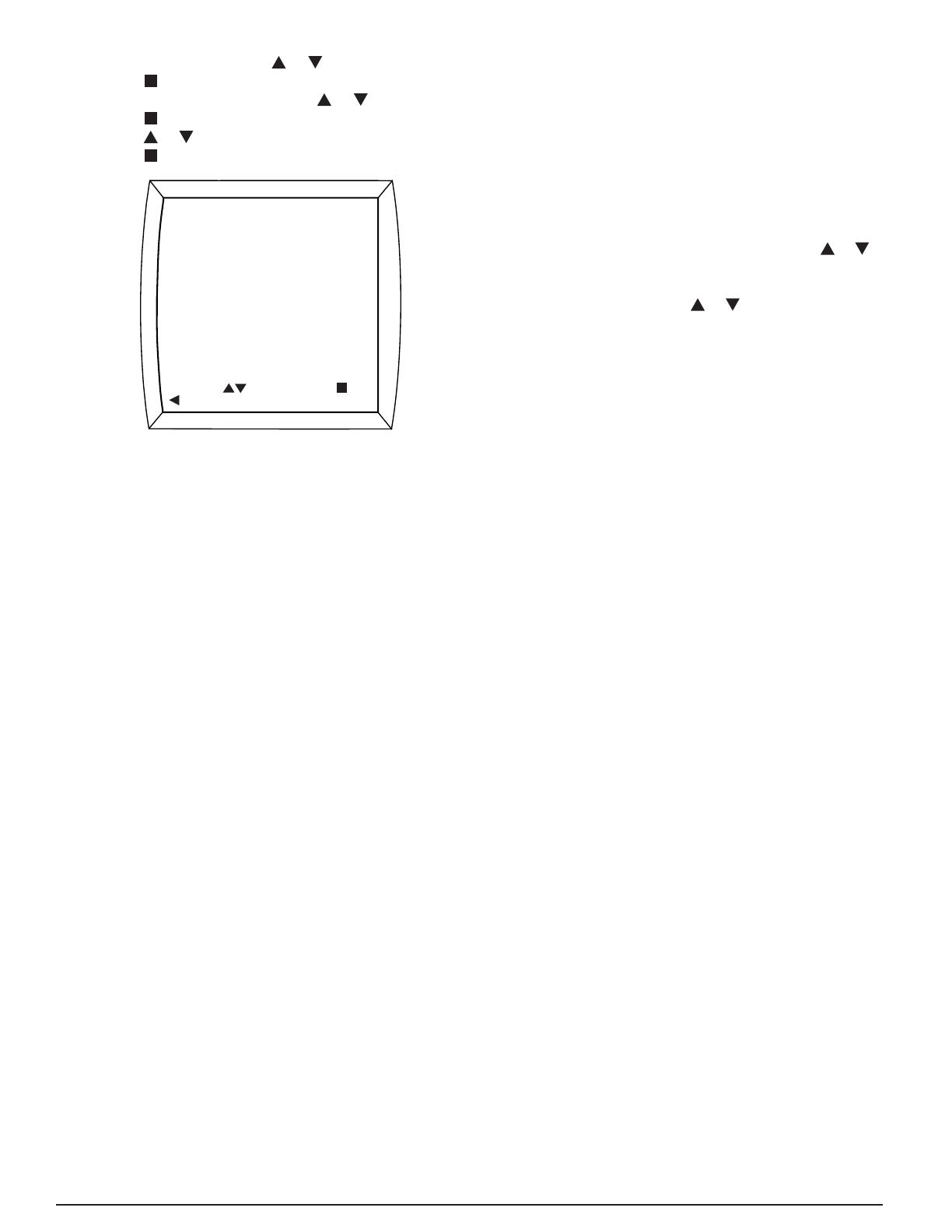
7. Press the
or button to change ENABLE to DISABLE.
8. Press the button to save the setting.
ZONE CONTROL
ENABLE
MODIFY
PREVIOUS
SAVE
ZONE CONTROL
To restore zone control (when the zoning system components
are functioning properly), follow the above sequence, but in
step 7 change DISABLE to ENABLE.
iQ Zone offers two types of ventilation that can be turned on
when the cooling or heating systems are not running:
• To deliver air to some but not all zones when not heating
or cooling, use the zone ventilation feature that is set up at
the individual zone thermostats. See the iQ Zone System
Zone Thermostat User’s Manual for information on how to
set up zone-by-zone ventilation. From the FAN MENU, enter
the VENTILATION SPEED screen in the iQ thermostat/
controller to select or modify the relative speed to be used
when this type of ventilation is operating.
To use the fan to deliver air to all zones when not heating
or cooling, set the Fan Mode to ON. The Intermittent Fan
feature described earlier will also operate, serving all zones.
Refer to the iQ Drive User’s Manual for other details relating
to zone control operation.
System Operation: Quick Start
The following is a summary of the sequence for typical
operation of the system.
1. Set the date and time (if not already set).
2. Check the program schedule for desired “setback”, and
modify if desired.
3. From the main screen, check/set the Fan operating mode:
AUTO operates the fan (indoor blower) when the unit is
cooling or heating. This is the “normal” setting.
ON operates the fan at the selected speed at all times.
The selected speed may change when the compressor,
electric heat, or furnace is operating.
PROGRAMMED FAN operates the fan in AUTO or ON
as specifi ed in the program schedule.
4. From the main screen, check/set the Mode:
COOL runs the air conditioner using the cooling setpoint.
(With iQ Zone, zone control enabled, there is a single
setpoint for both heating and cooling.)
HEAT runs the gas furnace or electric heat (whichever
is confi gured) using the heating setpoint. (With iQ Zone,
zone control enabled, there is a single setpoint for both
heating and cooling.)
OFF terminates either of the above.
NOTE: Equipment may not shut off immediately after
switching to OFF due to various system limitations.
Once put into the OFF mode, wait until the furnace or
compressor has shut off before selecting another mode.
5. For systems without iQ Zone, adjust the operating setpoint
if desired using a temporary hold (pressing the
or key
when the Main Screen is displayed). With iQ Zone, zone
control enabled, adjust the operating setpoint for each zone
individually by touching the
or icon. (Refer to iQ Zone
System Zone Thermostat User’s Manual for details.)
System Startup, Checkout, & Troubleshooting
The following is a summary of the sequence for typical fi rst
operation to check out the system. Reference is made to
INSTALLER SETTINGS and SERVICE INFORMATION
described above.
1. Install system hardware as described in the individual
component installation instructions.
2. Install power and control wiring to all system components,
including the controller, in accordance with the iQ Field
Wiring Installation Instructions.
3. Perform pre-charge evacuation of fi eld-installed refrigerant
lines as described in preceding sections.
4. For iQ Zone systems, fi rst apply 12 volt dc power to the zone
control board with the provided AC/DC converter. Apply
electrical power to the system (including the outdoor unit).
The controller screen display backlight should come on,
and the “iQ” splash screen should appear. If it does not,
trace the 24 vac control power to the “R” terminal on the
thermostat. CONFIGURATION NEEDED should appear
on the top line of the Main Screen (unless the thermostat
had been previously used on a similar iQ system).
5. Proceed with System Confi guration from the INSTALLER
SETTINGS menu (described above). On the SYSTEM
CONFIGURATION screen verify that the using size (2 ton,
3 ton, or 4 ton) is correct as indicated. If the wrong value
is shown, the inverter may require re-initialization. Contact
the service representative of the distributor in this case.
On the same screen, the entries under COMMUNICATION
should be followed by “OK”. If “CHECK” appears for a
communication item, go to the COMMUNICATION STATUS
screen (in the SERVICE INFORMATION menu, described
above), and view which elements are not communicating.
Trace and check the three communication wires throughout
the system. If isolating a communication problem proves to
be diffi cult, it may be useful to disconnect all communication
wires except those which link the thermostat and the non-
communicating element.
6. If COMMUNICATION STATUS was not checked during the
previous step, check it at this time. All listed items should
show a status of “OK”. If “BAD” is displayed, determine the
source of the problem as indicated in the previous step, and
resolve.
14
7. For iQ Zone systems only, the main screen should appear
with no temperature reading, and “ZONE CTRL” should
appear below “OFF”. If this is not the case, go to the ZONE
CONTROL screen from the SETTINGS menu, and change
the zone control option to ENABLE. If ZONE CONTROL
does not show up on that menu, the iQ controller has never
communicated with the zone control board, and power and
communication wiring to the zone control board need to be
checked. If the main screen reverts to back to the zoning-
disabled screen (showing room temperature), power and
communication wiring to the zone control board need to be
checked.
8. Set date and time as described above. This will provide a
“time stamp” for any fault which may arise during system
checkout.
9. If the installation includes a new gas furnace, check out
its operation fi rst. This may be best accomplished from
FURNACE TESTS under SERVICE TESTS from the
INSTALLER SETTINGS menu (see above). Follow steps
instructions provided in the furnace’s installation instructions.
Be sure to verify blower operation during the test.
10. If the outdoor temperature is above 60°F (14°C), test the
refrigerant system running in cooling mode. This may best
be accomplished from CHARGE MODE under SERVICE
TESTS from the INSTALLER SETTINGS menu. Follow the
refrigerant charge adjustment procedure explained above.
11. When charge adjustment is completed (if required), run
the system in cooling mode. This may also be done using
SERVICE TESTS although some diagnostic messages
are disabled in that method.
12. Check the FAULT STATUS screen (described above) for
any faults logged during the startup process. Any message
listed as “ACTIVE FAULT” refers to a condition which either
still exists or occurred within the preceding 5 minutes. Every
fault or notifi cation should appear in the FAULT HISTORY
log which starts on the same screen. The last 10 faults
to have occurred are retained in this list. Each new item
pushes other logged faults down in the list. The second line
associated with each of the 10 entries includes the time
and date of detection. While the wording of fault messages
is intended to provide a reasonable indication as to the
responsible condition, the information conveyed by the
abbreviated wording is limited. Consequently the installer
should refer to training literature for further information in
understanding fault messages.
13. If needed, make use of information provided below under
Troubleshooting: What to Expect with Normal Operation.
14. Independently confi rm operation of any accessories
installed with the air conditioning system following
instructions provided with that equipment.
15. Complete the remainder of confi guration settings and
entries as specifi ed above under Installer Settings and
Other Confi guration Entries.
16. For iQ Zone systems, confi rm the zone system setup by
checking information on the ZONING DATA and ZONE
MODULE STATUS screens, accessed from the SERVICE
INFORMATION menu. (See SYSTEM DIAGNOSIS AND
TROUBLESHOOTING below.).
SYSTEM DIAGNOSIS & TROUBLESHOOTING
The following is a summary of normal and abnormal operation
for typical startup to check out the system. Reference is made
to INSTALLER SETTINGS and SERVICE INFORMATION
screens described above. Refer to training literature for more
details.
Diagnostic information for the air conditioning system can be
obtained from all of the following sources:
Controller displays. Refer to training materials for
interpretation of fault messages which appear on the Main,
Fault Status, and Service Needed screens.
Refrigerant system pressure and temperature measurements
(using standard fi eld service instrumentation)
LED indicator lights on each of the system’s circuit boards
(see below).
Controller
Normal - As soon as 24 vac power is applied, the blue backlight
of the controller should light up. The “iQ” splash screen will
display the software version. If the System Confi guration
procedure has not been performed yet for this system-controller
combination, “CONFIGURATION NEEDED” will be displayed
across the top (alternating with other information).
If the system has a Type “P” blower motor (shown on SYSTEM
CONFIGURATION and INDOOR FAN STATUS screens),
used in air handlers or G6 gas furnaces, the blower will self-
calibrate for 60 seconds as soon as System Confi guration is
completed.
All communications links in COMMUNICATION DATA
should show “OK”. All information displayed in the System
Confi guration screen should be accurate.
Abnormal – If the display is not lit, check that 24 vac is being
provided between the “R” and “C” terminals in the thermostat’s
back connection plate. If not, trace the connection of all
controller wires back to the indoor unit (furnace or air handler).
Check that connections are in accordance with fi eld wiring
diagrams and instructions.
If a SERVICE NEEDED screen with a red backlight is displayed,
a fault has been detected. A brief description of the fault is
displayed on the screen. Access to the FAULT STATUS
screen is permitted.
If communication with the outdoor unit is OK but the unit size
(in tons) shown on the System Confi guration screen in wrong,
contact the service representative of the equipment distributor.
The inverter may not have undergone its initialization
procedure, performed at the factory.
15
Outdoor Unit Inverter
WARNING:
ELECTRIC SHOCK HAZARD!
Disconnect power before servicing the outdoor
unit. Failure to follow these instructions may result
in electric shock or death. Trouble-shooting the
outdoor unit may require that power be restored with
the control panel cover removed. Become familiar
with the control panel and hazardous voltage areas
before proceeding.
Time is required for inverter voltage to bleed down
after removal of line power. Wait at least 60 seconds
after removing line voltage before touching any
inverter parts or wiring.
Normal – Examine the following with the control panel cover
off. The small red LED on the upper right side of the inverter
panel should be lit and on steady when power is applied to
the inverter. Refer to Figure 3.
Abnormal –The red LED on the inverter is not lit. In this case,
power is not being provided to the inverter. Check that line
voltage is being applied to the bottom of the contactor. If so,
check that 24 vac is being provided across the contactor coil
(between the tabs on the right and left side of the contactor).
If not, check the 24 vac control power source wiring to the
outdoor unit. Check that the high pressure switch is closed.
A fault indicating OD UNIT COMM FAULT or OD UNIT LOST
POWER would also result from no line voltage applied.
The red LED on the inverter is lit but blinking. This indicates
that the inverter is powered up and that it detects a fault
condition. If the controller does not display a fault message,
put the unit into COOL mode, and a message will be displayed.
NOTE: When line power is removed, the red LED will blink
for about 1 minute before going out.
Indoor Unit Interface Board
(in G6 iQ furnace kit or air handler)
Normal – The red LED at the upper left of this board should
do a “heartbeat” blink, consisting of a double-blink followed
by a pause, repeated. Note 4 other LEDS towards the lower
edge of the board. When the equipment is off, none of the
LEDs should be on. If the furnace or electric strip heat is on,
3rd LED or 3rd and 4th LEDs from the right should be on (fi rst
and second stage heat). When the unit is cooling the right-most
LED should be on (EXV enabled to open). If humidifi cation is
called for, the 2nd LED from the right should be on.
Abnormal – If no LEDs are lit on the board, 24 vac control
power is not being provided across the “R” and “C” terminals.
Check for this voltage between the left-most two screw
terminals (labeled R and C).
Indoor Unit EXV Board
(at the indoor coil, furnace, or air handler)
Normal – The green LED at the upper left of this board should
be steadily on.
Abnormal – If the green LED is not lit, the EXV board is not
getting 24 vac power from the interface board. Check for
24 vac between R and C on the interface board, and check
that the tabs marked “R” and “C” on the interface board are
wired to “R” and “C” on the EXV board. These should not be
cross-wired.
If the green LED is blinking at a regular rate during cooling,
it indicates that one of the two EXV sensors is reading out
of range. Refer to training literature for sensor interpretation
and troubleshooting.
If the green LED is blinking at a non-uniform rate (heartbeat), it
indicates that the board has been placed in the Manual Mode.
Hold down the small black button on the board for more than
3 seconds to return it to automatic control mode.
Indoor Unit Constant CFM Motor Control Board
Normal – The red LED near the top of the board should be
on steadily. The green LED near the top of the board should
have a “heartbeat” blink, consisting of a double-blink followed
by a pause, repeated. Of the four LEDs towards the left side
of the board, the lowest one marked “H” should be on when
humidifi cation is called for.
Abnormal – If the green LED near the top of the board is not
lit, the board is not connected to the communication network
properly. If the red LED near the top of the board is not lit, the
board is not getting 24 vac control power from the furnace board.
Indoor Unit One- or Two-Stage G7 Furnace Board
Normal – The red and green LEDs should be on steadily.
When the furnace is on and a fl ame is detected, the amber
LED should be on.
Abnormal – The LEDs will provide a diagnostic code through
their blink pattern. Refer to furnace Installation Instructions
for detailed troubleshooting.
Indoor Unit iQ Modulating Gas Furnace Board
Normal – The red LED should be on steadily. The green LED
near the top of the board should have a “heartbeat” blink,
consisting of a double-blink followed by a pause, repeated.
When the furnace is on and a fl ame is detected, the amber
LED should be on.
Abnormal – The LEDs will provide a diagnostic code through
their blink pattern. Refer to furnace Installation Instructions for
detailed troubleshooting. If the green LED alone is not lit, the
board is not connected to the communication network properly.
16
Airzone Control Board
Normal – One red power LED should be on steady near
where the dc power plugs into the board (upper left corner).
Red and green LEDs at the lower right side of the board (just
below the DIP switch block) fl ash quickly and continuously
(indicating zone network activity). A second set of red and
green LEDs (about 1” to the left of the other green and red
LED pair) also fl ash, with the red LED fl ashing every 3 to 5
seconds, indicating iQ bus communication. See Figure 15.
Abnormal – If the red LED near the dc power plug is not on,
then the AC/DC power supply is not connected or not working.
If the red LED 1 ½” from the lower right edge does not fl ash,
the module is not communicating properly on the iQ bus.
iQ Zone System Confi guration
Normal – Check the ZONING DATA screen from the SERVICE
INFORMATION menu (shown here). In the lower portion of
the screen the zone weights shown should match the intended
values, and they should add up to 100(%).
ZONING DATA
PREVIOUS
12345678
ZONES ACTIVE
AZF
HEAT DEMAND
COOL DEMAND
MODE
ZONE FLAGS
ZONE WEIGHTS
ZONE 1 40
ZONE 2 25
ZONE 3 15
ZONE 4 10
ZONE 5 10
ZONE 6 0
ZONE 7 0
ZONE 8 0
DETAILS
OUTPUT
00100001
65
-90
400
COOL
10000001
NF
Press the key to view the ZONE MODULE STATUS screen
(shown here). Every module installed in the system should
show up on this list with the proper zone identifi cation number
after the “Z”, followed by a “0”. For example, “23Z40” is
module 23 in zone 4. The “0” indicates normal functioning.
Zone numbers should only appear with module numbers that
were intended to be assigned. For master zone modules 1-8,
the zone number must match the module number.
ZONE MODULE STATUS
PREVIOUS
MOD
1Z10
2Z20
3Z3X
4Z40
5Z50
6Z
7Z
8Z
9Z10
10Z12
MOD
11Z10
12Z10
13Z20
14Z23
15Z20
16Z20
17Z3X
18Z3X
19Z42
20Z40
MOD
21Z50
22Z
23Z
24Z
25Z
26Z
27Z
28Z
29Z
30Z
31Z20
32Z
Abnormal – If any zone weight shown in the ZONING DATA
screen is incorrect, or if the total for the eight zones is not
100(%), make the appropriate corrections from the zone
thermostat for the zone(s) which require(s) correction.
If an installed zone module does not show up in the ZONE
MODULE STATUS screen with an assigned zone number,
such as with module 25 in the fi gure, check the wiring to that
zone module. If the zone number is wrong or if the wrong
module number shows up as used, the module needs to be
reconfi gured. If the last character after the zone number is
not “0”, look for the following problems:
“1” may indicate a disconnected damper motor connector.
“2” may indicate a damper that is jammed due to blockage
from a foreign object or damage or dirt on the internal
transmission.
“3” may indicate that a zone thermostat is not connected
properly to its associated master zone module (1-8).
“X” may indicate that a module is assigned but not
communicating.
Common Troubleshooting Issues
Compressor Does Not Start Immediately
For normal operation without changing modes of operation,
the compressor will not restart until 5 minutes (the minimum
off time) have expired since it shut off last.
A minimum demand of 0.5°F is required before the air
conditioner will start up.
The system will wait 5 minutes following detection of a fault
condition before attempting a restart.
Compressor Does Not Shut Off Immediately
For normal operation without changing modes of operation,
the compressor will not shut off until 5 minutes (the minimum
run time) have expired since it started last.
The Outdoor Fan Does Not Shut Off When the
Compressor Does
For normal operation the outdoor fan is designed to run for
30 seconds after the compressor shuts off.
In Cooling, the Blower Slows Down and the Unit
Is Not Responding to Room Temperature
Slowing of blower speed and suspension of normal capacity
control will occur when the unit goes into Dehumidifi cation.
If conditions for dehumidifi cation persist, the unit will run
cycles of 10 minutes in dehumidifi cation, 5 minutes in normal
cooling (responding to room temperature).
The System Is In AUTO Mode, but It Won’t Switch
Quickly From Heating to Cooling (or the Reverse)
There is a confi gurable delay (Auto Changeover Time)
between operating in heating and restarting in cooling (or
the reverse) when in AUTO mode. The default delay for
this changeover is 60 minutes.
17
Although There Is a Large Demand At Startup,
the Compressor Only Runs at Medium Speed
Regardless of demand the system will always start and run
at an intermediate speed for one minute. Subsequently the
speed may increase signifi cantly.
Humidifi cation or Dehumidifi cation Setpoints Are
Not Being Satisfi ed
The fi rst priority of the system is to achieve the temperature
setpoint(s). While under most circumstances it will also
satisfy humidity setpoints, its ability to accomplish this is
signifi cantly affected by a variety of installation-based factors
and circumstances.
In an iQ Zone System, the system does not
respond promptly to changes in setpoint or mode
With zoning systems additional delays may be noticed.
Most commonly this is due to no new changes processed
until zone dampers have completed any prior operation.
For example, an extra minute delay is deliberately included
when one or more zones are closed.
MAINTENANCE
IMPORTANT:
Be certain the electrical power to the outdoor unit
and the furnace or air handler is disconnected before
doing the following recommended maintenance.
Inspect the indoor air fi lter monthly. Clean or replace it at
the start of each heating and cooling season or when an
accumulation of dust or dirt is visible. If the indoor coil needs
to be cleaned, contact a qualifi ed service technician.
Inspect the condensate disposal line from the indoor coil at
the beginning of the cooling season to make sure it is not
obstructed.
• Remove any leaves, grass clippings, and debris from the
outdoor unit coil, being careful not to damage the aluminum
ns. Dirt may be cleared from the coil by using a water hose
directed through the discharge fan grille toward the outside
of the unit.
Have a yearly inspection by a qualifi ed service technician
to ensure that the system is performing at its optimal level.
Figure 2. Power Wiring Connections
Figure 1. Unit Envelope Dimensions
18"
CONTROL
PANEL
EXTERIOR WALL
18"
18"
18"
FIGURES & DIAGRAMS
18
Figure 3. iQ Drive Air Conditioning Control Panel
Red Inverter
LED
Inverter
(Black Plastic
Case)
Low Voltage
Control Wiring
Compartment
Contactor
19
FIELD WIRING
LEGEND:
LOW VOLTAGE
HIGH VOLTAGE
INVERTER
1
2
34
5
6
7
6
5
43
2
1
TA6
TA5
TA8 TA1
TA2
TA3
TA7
TA4
CN7
CN8
CN11
GND
DX-
DX+
1
2
3
4
1
2
CN3
CN6
WVU
MARK
STAMP
“TO W”
“TO V” “TO U”
C (On Gasket)
S (On
Gasket)
R (On
Gasket)
O.D.
FAN MOTOR
OUTDOOR TEMP
THERMISTOR
COMP DISCH TEMP
THERMISTOR
TO INDOOR UNIT
THRU
TOROIDAL
RING TO L.V.
BARRIER
3X
OUTDOOR POWER
SUPPLY
Single Phase
HPS
FUSE
FUSE
THRU CORE
RING
LPS
COMPRESSOR
REACTOR
THRU
TOROIDAL
RING
2X
T2
T1
L1
L2
CONTACTOR
*TERMINALS ON COMPRESSOR
ARE NOT MARKED. USE
RELATIVE LOCATION OF
TERMINALS TO THE MARK
STAMP TO IDENTIFY
PROPER POSITIONS.
GROUND
L1
L2
CABLE
GREEN
YELLOW
WHITE
BLACK
BLACK
GREEN
RED
BLACK
ORANGE
BLUE
YELLOW
GREEN
GRAY
BLACK
YELLOW
YELLOW
RED
BLACK
BLACK
BLACK
BLACK
YELLOW
YELLOW
BLACK
RED
YELLOW
BLACK
YELLOW
Figure 4. iQ Drive Air Conditioning Wiring Diagram
20
Figure 5. Low Voltage Control Wiring Compartment
  • Page 1 1
  • Page 2 2
  • Page 3 3
  • Page 4 4
  • Page 5 5
  • Page 6 6
  • Page 7 7
  • Page 8 8
  • Page 9 9
  • Page 10 10
  • Page 11 11
  • Page 12 12
  • Page 13 13
  • Page 14 14
  • Page 15 15
  • Page 16 16
  • Page 17 17
  • Page 18 18
  • Page 19 19
  • Page 20 20
  • Page 21 21
  • Page 22 22
  • Page 23 23
  • Page 24 24
  • Page 25 25
  • Page 26 26
  • Page 27 27
  • Page 28 28

Broan PSA4BI Installation guide

Category
Thermostats
Type
Installation guide
This manual is also suitable for

Ask a question and I''ll find the answer in the document

Finding information in a document is now easier with AI