Page is loading ...

Phone: (855) 770-5678 | http://www.daikinac.com
4008862
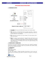
ZONING BOX CONTROL BOARD
• Individually controlled dampers.
• Q-Adapt algorithm.
• Control of optional auxiliary heat (up to two stages).
• Supply temperature sensor.
• Seamless integration with the Indoor Unit Control.
o On/Off status.
o Fan speed Algorithm.
o Indoor Unit Set point.
o Operation Mode.
o Energy Efficiency Control Algorithm.
• It allows bus connection of up of 6 Wired Thermostats.
DZK-CB-3
Rev. 2.00
10-2018
TECHNICAL SPECS
Power supply and consumption
Type of power supply
Vac
V max
110 / 230 V
I max
250 mA
Frequency
60/50 Hz
Stand-by consumption
400 mW
Protection
Self-Resettable Fuse*
Expansion bus
Nº of ports
3
Shielded twisted pair
AWG 20 – 4 wired
Maximum wiring length
(Control board to Main thermostat)
130 ft (40 m)
V max
12 V
Connector for optional BACnet Interface board
Nº of ports
1
Communications protocol
MODBUS RS-485
Par – 19200 bps
Communication BACnet Network – BACnet/IP
Wireless communication
Communications protocol
Airzone proprietary protocol
Frequency
915 MHz
Radiation power
5 dBm
Maximum wireless reach
(Control Board to Wireless thermostat)
130 ft (40 m) in clear line of sight
Actuator control outputs
Nº of outputs
6
Vmax
± 12 V
Imax
150 mA
Auxiliary heat outputs
Nº of outputs
2
V max
24 / 48 V
I max
1 A
Alarm input
Type of alarm input
Dry contact (Normally Closed)
Operating temperatures
Storage
-4 … 158ºF (-20 … 70 ºC)
Operation
32 … 122ºF (0 … 50ºC)
Operating humidity range
5 … 90% (non-condensing)
Mechanical aspects
Protection class
IP 20
Weight (Mass)
0.45 lb (204 g)
Dimensions (WxH)
6.89x4.79 inch
(175.1 x121.6 mm)
*Electronic component that opens the electrical circuit and cycles back to a conductive
state after current is removed.
W
H

REPLACING THE CONTROL BOARD
Disconnect the power cable before starting the replacement of the DZK Zoning Box control board. Once the installation is finished reconnect the power cable.
Unscrew the cover, the screws are self-retaining.
Release the clamps holding the cables.
Disconnect all connectors.
Unscrew the four screws holding the plastic box
to the DZK zoning box control board.
Reinstall the cable clamps and insert the cover and screw in the retaining screws.
Install the new DZK zoning box control board,
using the same screws. Be sure the damper
connectors are on the upper
side.
Reconnect all the connectors as they were previously installed. Check that the damper
cables numbers correspond to the connectors numbers in the control board.
Once the installation is finished reconnect the power cable. Once the Zoning box control board is powered on, all the wireless thermostats
must be reset (see the Installation’s Manual); all system and zone parameters must be entered, following the initial installation procedure.

Phone: (855) 770-5678 | http://www.daikinac.com
4008862
WIRED THERMOSTAT CONFIGURATION
WIRELESS THERMOSTAT CONFIGURATION
When replacing the DZK zoning box control board, the wired thermostat configuration will not be reset. The time schedules will be the only feature reset. It is necessary to reprogram the personalized time schedules (see the User’s Manual).
In order to associate the Wireless Thermostats, the radio channel has had to be opened. To open the radio channel, press on SW1 (Main Control Board), the LED 19 will remain solid red for 15 min. You can also open the channel association radio
trough the Main Wired Thermostat (see the Installation’s Manual).
Select your language and press Airzone to
confirm.
To associate the thermostat, press Airzone.
Verify that received signal power is correct (30%
minimum) and press on Airzone to confirm.
Select the number of zone associated to the
thermostat.
Select Associate and press Airzone if additional
outputs are needed for this controller/zone.
If no additional outputs are required for this
zone, proceed to step 6.
Select Continue and press Airzone if no
additional outputs are required for this
thermostat/zone.
To finish the initial setup, press Airzone.
Select the desired output from the list of
available outputs and press Airzone.

WIRELESS LITE THERMOSTAT CONFIGURATION
In order to associate the Wireless Lite Thermostats, the radio channel has had to be opened. To open the radio channel, press on SW1 (Main Control Board), the LED 19 will remain solid red for 15 min. You can also open the channel association radio
trough the Main Wired Thermostat (see the Installation’s Manual).
Select the zone number associated to the thermostat by switching on the corresponding number of the DIP switch.
If required, select other control outputs associated to the zone by adjusting the corresponding dip switches.
The address zone will be the one with a lower value.
Configure other functionalities of the Wireless Lite Thermostat from the Advanced Configuration menu of any Wired Thermostat.
/