
C-Series (C-120, C-150, C-170)
Installation Instructions
No. Part Name C-120
2
1
3
4
5
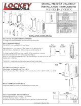
Outside Body
Inside Body
Rubber Trim Plate
Surface Strike Plate
Morsed Striker (not shown)
Machine Screws M4 x 30, 35 & 40mm
Machine Screw M5 x 20mm
Wood Screw M4 x 16mm
Extra Code Tumblers (Red)
Extra Non-Code Tumblers (Blue)
Thin Door Kit (TDK) (not shown)
Spacers (not shown)
Tweezers
Hex Bolts
6
9
10
11
12
13
14
15
1
1
1
2
1
3
2
2
1
2
1
3
1
2
Spindle
7
8
C-170
1
1
0
2
0
1
0
2
1
2
1
3
1
2
1|1|1 1|1|1 1|1|1
Step 1: Change User Code/Combinaon (OPTIONAL)
To change user code/combinaon, see instrucons on reverse side.
Step 2: Prep Door for Installaon with Template
Place template (supplied) on door and fold along door’s edge.
Depending on door configuraon, you may need to change handing and/or reverse the bar (C-120) from long to short. See Steps 3 & 4.
Drill holes as instructed and mark locaon for Strike.
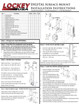
Step 3: Idenfy Door Handing
Right-Hand Doors – From exterior of door, hinges are on right-side (Fig. 1).
Le-Hand Doors – From exterior of door, hinges are on le-side (Fig. 2).
The C-120, C-150 and C-170 are factory pre-handed for right-hand doors.
To change handing, remove the two blue screws and cover plate from Outside Body (#1) as shown.
Next, move the pin from the right side of the Outside Body (#1) to the hole on the le side.
Replace plate and screws.
Step 4: Adjust Deadbolt Length (C-120 ONLY, if necessary)
Depending on door configuraon, you may need to reverse the bar from long to short.
Remove silver screws and plate from the Inside Body (#2).
Reverse the bar.
Replace plate and secure with silver screws.
Step 5: Verify Correct Spindle Length
Hold the Inside Body (#2) and Rubber Trim Plate (#3) to the door.
Place Spindle (#6) through door into the Inside Body (#2), as far as possible.
Spindle (#6) should extend from exterior of door 3/8” minimum to 5/8” maximum.
If Spindle (#6) is too long, cut it to the correct length using pliers.
IMPORTANT: If Spindle (#6) extends less than 3/8”, it may not engage the lock.
If Spindle (#6) extends more than 5/8”, it will cause the lock to bind.
Connued on Reverse Side
C-120
C-150
1
1
1
2
1
3
2
2
1
2
1
3
1
2
C-150
C-170
15
15
14
11
Updated 6.1.16
= 3/8” to 5/8”

C-Series Instructions
Continued...
Updated 6.1.16
Step 6: Installaon
Place the Rubber Trim Plate (#3) on the backside of the Outside Body (#1).
Place the Outside Body (#1) on the door. The Hex Bolts (#15) should extend into the top and boom holes.
Insert the Spindle (#6) through the door into the spindle hole on the Outside Body (#1).
Place the Rubber Trim Plate (#3) on the backside of the Inside Body (#2).
Place the Inside Body (#2) to the door ensuring that the Spindle (#6) is inserted into the spindle hole.
If the Inside Body is not flush with the Surface Strike (#5) locaon, use Spacers (#13) to make Inside Body flush with Strike locaon.
NOTE: If Spacers do not make Inside Body flush with Strike locaon, you may need to trim the door jamb or morse the strike.
Insert screws into the top and boom holes of the Inside Body and secure with a screwdriver.
Test the lock to ensure the Deadbolt/Hookbolt is retracng correctly when turning the inside/outside knob.
Install Strike Plate (#5) (C-120 & C-150 only) in proper posion and secure with Wood Screws (#9).
Step 7: For Doors Under 1” Thick (if necessary)
For doors under 1” thick, you will need to cut the Spindle (#6) to the appropriate size. See Step 5 to verify correct spindle length.
Remove Hex Bolts (#15) and use M5 Screws supplied in Thin Door Kit packet to secure lock to door.
Step 8: Using the C-Series Lock
From Outside:
The door will LOCK by turning the thumbturn to extend the deadbolt/hookbolt.
To UNLOCK, turn the thumbturn to clear the lock, enter the combinaon and turn the thumbturn to retract the deadbolt/hookbolt.
NOTE: If the deadbolt/hookbolt retracts without combinaon and requires a combinaon to lock (extend), you may need to change
handing. See Step 3.
From Inside:
The door will LOCK and UNLOCK by turning the thumbturn to extend or retract the deadbolt/hookbolt.
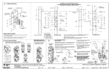
1. Using a #2 screwdriver, remove the two (2) Red Screws.
2. Carefully remove cover plate.
WARNING: Springs are aached to plate.
6. Replace the cover plate and secure with two (2) Red Screws,
using a #2 screwdriver.
7. TEST CODE before installing/re-installing lock.
3. TURN & HOLD thumb-turn to right or le 90° to release tumblers.
IMPORTANT: THUMB-TURN MUST be turned 90°and held when
removing and inserng tumblers. Failure to do so will damage the
lock and void the warranty.
WARNING:
Do NOT force tumblers into posion!
TURNING THUMBTURN 90°= CLEAR POSITION.
4. With the thumb-turn held 90° to right or le, remove/add
CODE (Red) and NONCODE (Blue) tumblers to create the desired code.
Ex: 3 Red = 3-Digit Code / 6 Red = 6-Digit Code
5. Aer changing your code, release the thumb-turn to secure the
tumblers in place.
How to Change User Code/Combinaon
For more helpful ps and installaon instrucons, visit www.LOCKEYUSA.com
SAVE


-
 1
1
-
 2
2
-
 3
3
-
 4
4
-
 5
5


LOCKEY C-Series Keyless Entry Sliding Installation guide
- Type
- Installation guide
- This manual is also suitable for
Ask a question and I''ll find the answer in the document
Finding information in a document is now easier with AI
Related papers


Other documents
-
 LOCKEY USA M210-DC-MG User manual
-
 LOCKEY USA M220 User manual
-
LOCKEY USA 2900 Mechanical Keyless Narrow Stile Deadbolt Lock User manual
-
LockeyUSA 1600 Operating instructions
-
 CARGO VAN LOCKS 2006 User manual
-
Kaba E-PLEX 5X51 Installation guide
-
Assa Abloy 75 User manual
-
Dormakaba kaba E-Plex 7900 Installation guide
-
-
 ADAMS RITE 2190 series Installation guide


