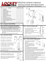
LOCKEY 2900 KEYLESS LOCK Operating instructions

Type
Operating instructions

LOCKEY 2900 KEYLESS LOCK offers enhanced security and convenience for your home or office. With its keyless entry system, you can easily unlock the door using a personalized code, eliminating the need for physical keys. The lock features a durable construction and allows you to customize the code to your preference, providing a unique and secure access solution. It's suitable for both residential and commercial applications, ensuring peace of mind and hassle-free entry.

LOCKEY 2900 KEYLESS LOCK offers enhanced security and convenience for your home or office. With its keyless entry system, you can easily unlock the door using a personalized code, eliminating the need for physical keys. The lock features a durable construction and allows you to customize the code to your preference, providing a unique and secure access solution. It's suitable for both residential and commercial applications, ensuring peace of mind and hassle-free entry.

1
2
12
9
8
4
3
10
5
11
7
6
10
12
8
8
9
2
3
1617
16
14
13
15
18
18
16 10
5
6
3
11
971218
17
15
13
14
6 8
1
2
3
12
5
10
9
9
11
88
3
10
12
24
7
BILL OF MATERIALS
NOTE:
READ INSTRUCTIONS COMPLETELY AND CHECK ALL APPLICABLE CODES BEFORE INSTALLING.
ITEM #
DESCRIPTION
QTY
1
OUTSIDE BODY
1
2
HEX STANDOFF
2
3
M4 X 0.7 X 50 OVAL HEAD SCREW
2
4
SPINDLE 40MM-55MM
1
5
INSIDE BODY
1
6
STRIKE PLATE
1
7
FACE PLATE
1
8
#8-32 X 1/4" FLAT HEAD SCREW
3
9
#10-32 X 1/2" FLAT HEAD THREAD-CUTTING SCREW
2
10
RUBBER TRIM PLATE
2
11
LOCK ASSEMBLY
1
12
#10-32 X 1-7/8" FLAT HEAD SCREW
2
13
THREADED STUD
1
14
TWEEZERS
1
15
SPINDLE 30MM-45MM
1
16
NON-CODE TUMBLER (BLUE)
2
17
CODE TUMBLER (RED)
1
18
M4 X 0.7 X 35 OVAL HEAD SCREW
2
www.lockeyusa.com
INSTALLATION INSTRUCTIONS
KEYLESS LOCK
2900 & 2950
5-25-22
BY: AMM
PAGE 1 OF 4
REV. 00
Figure 7
NOTE: DO NOT
REMOVE "C"
TUMBLER
TUMBLER
Figure 3
A
PIN
CONFIGURATION B
POSITION
CONFIGURATION A
POSITION
Figure 8
OUTSIDE BODY
MUST PRESS AND
HOLD "C"BUTTON
WHEN REMOVING
/ INSERTING
TUMBLERS
Figure 2
B
NOTCH
NOTCH
Figure 4
BUMP
RED
CODE
TUMBLER
BUMP
COVER
PLATE
Figure 1
RED SCREWS
CONFIGURATION B
OUTSIDE BODY
INSIDE BODY
CONFIGURATION B
Figure 6
OUTSIDE BODY
INSIDE BODY
CONFIGURATION A
OUTSIDE BODY
INSIDE BODY
CONFIGURATION A
Figure 5
OUTSIDE BODY
INSIDE BODY
BLUE
NON-CODE
TUMBLER
PART 1: CHANGING THE CODE
IMPORTANT NOTES
The ‘C’ button must be pressed and held down when removing and inserting tumblers. Failure to do so will damage the lock and void the warranty.
The DC versions with two combination bodies come with a different code on each side. Both sides must have the code and door configuration set individually.
1) Using a #2 screwdriver, remove the four red screws (Figure 1).
2) Carefully remove the cover plate. NOTE: The springs are attached to the plate.
3) WARNING: The "C" button must be pressed and held while removing or adding tumblers (Figures 2 and 3). Do not remove the "C" tumbler (Figure 3). While
holding down the "C" button, remove a CODE (Red) or NON-CODE (Blue) tumbler using the included tweezers, and replace it with the opposite type to create the
desired code (Figure 3). The colored end must face out for each tumbler, and the bump of the tumbler must be aligned with the notch in the slot (Figure 4). The
installer can choose how many CODE tumblers versus NON-CODE tumblers to use to make the code longer or shorter.
4) After changing the code, release the "C" button to secure the tumblers in place.
5) Replace the cover and secure with four red screws using a #2 screwdriver.
6) Test the new code before installing/reinstalling the lock.
COLORED END
PART 2: IDENTIFY DOOR CONFIGURATION
NOTE: For 2900 DC and 2950 DC, the inside body handing pin must be placed on the opposite side as the outside body.
Configuration A: Shown in Figure 5.
Configuration B: Shown in Figure 6.
1) The 2900 and 2950 outside bodies come set up for Configuration A. To change to Configuration B, remove the two blue screws and cover plate from the outside
body as shown in Figure 7. Next, move the pin from the left side of the outside body to the hole on the right side (Figure 8). Replace plate and screws.
2) Test each lock with code for proper door configuration and operation.
PART 2: IDENTIFY DOOR CONFIGURATION
Configuration A: Shown in Figure 5.
Configuration B: Shown in Figure 6.
1) Before installation, test each combination body by entering the code and turning the knob toward the hinge side. If the knob does not unlock when turned toward
the hinges, the handing pin will need to be moved according to the next step. NOTE: For a DC lock, test both the outside body and inside body, noting that the hinge
side of the inside body will be opposite the hinge side of the outside body.
2) To change the handing of the combination body, remove the two blue screws and cover plate from the back of the body as shown in Figure 7. There are two holes
available for the handing pin, with the configuration positions of the outside body shown in Figure 8 (the configuration positions are reversed for the inside body).
Move the handing pin from its current hole to the other open hole. Replace the cover plate and screws.
3) Test each body with its code for proper door configuration and operation.
www.lockeyusa.com
INSTALLATION INSTRUCTIONS
KEYLESS LOCK
2900 & 2950
5-25-22
BY: AMM
PAGE 2 OF 4
REV. 00
TEMPLATE
SPINDLE HOLE
ON BOTTOM
DOOR
Figure 9
TEMPLATE FOLD
LOCATE TEMPLATE
WITH HORIZONTAL
LINES CENTERED
OVER HOLES
Figure 10
MOUNTING
HOLE
MOUNTING
HOLE
SPINDLE
HOLE
3/8" MIN
5/8" MAX
Figure 11
INSIDE
BODY
SPINDLE
OUTSIDE
BODY
RUBBER TRIM PLATE
INSIDE BODY
FACE PLATE
LOCK ASSEMBLY
Figure 12
DOOR
RUBBER TRIM PLATE
HEX STANDOFF
M4 OVAL HEAD SCREWS
#8-32 X 1/4" FLAT
HEAD SCREWS
#10-32 X 1-7/8" FLAT
HEAD SCREWS
SPINDLE
INSIDE BODY SPINDLE HOLE
PART 3: INSTALLING THE LOCK
NOTE: The 2900 Deadbolt and 2950 Hook Bolt are designed for narrow stile prep doors or to replace
configurations with existing narrow stile hardware with 1-1/8” prep (Adams Rite). For 1-1/8” narrow stile
prep doors, please skip to Step 2.
1) Remove all previously installed hardware. NOTE: Do not discard previously installed trim / face plate
since it may be used.
2) Check template scaling to guarantee proper measurements and hole pattern. Fold at line indicated.
3) With the template folded at a 90-degree angle (Figure 9), locate the template by placing the horizontal
lines of the template over the center of the holes on the side of the door. Mark the centers of the three
holes on the template. NOTE: Ensure the spindle hole is placed at the bottom. This mounting is opposite
compared to most Adams Rite configurations.
4) Drill three holes at the marks made in the previous step using the drill sizes listed on the template.
5) Insert lock assembly and secure with two #10-32 X 1-7/8" flat head mounting screws. Ensure that the
spindle hole is on the bottom (Figure 10).
6) To verify correct spindle length, hold inside body to the door (Figure 11). Place the 40MM-55MM
spindle through the spindle hole of the lock assembly.
Spindle should extend from exterior of door
3/8” min. to 5/8” max.
If the spindle is too long, use the shorter spindle and measure again or cut it to
the correct length using pliers.
7) Install two hex standoffs in the outside body (Figure 12), place the rubber trim plate on the outside
body and place the outside body on the outside of the door. Insert the spindle into the spindle hole.
8) Place the rubber trim plate on the inside body. Place the inside body on the door so that the spindle
goes into the spindle hole of the inside body (Figure 12). Secure using the provided M4 oval head
screws (use either the 35MM long or 50MM long screws depending on your door thickness).
9) After installing the lock, replace and secure the face plate using three #8-32 X 1/4" flat head screws.
IMPORTANT NOTES
Due to variances in face plate sizes, you may need to use the previously installed face plate.
The strike plate may need to be modified to accommodate the 2900 Deadbolt/2950 Hookbolt or the
included strike plate may be used.
In some cases, the rubber trim plate may need to be trimmed on the inside body to allow proper door
closure. This is due to the jamb edge on the interior of the door. In rare cases, you may also need to
trim the jamb edge to accommodate the lock.
www.lockeyusa.com
INSTALLATION INSTRUCTIONS
KEYLESS LOCK
2900 & 2950
5-25-22
BY: AMM
PAGE 3 OF 4
REV. 00
DRILL
3/8"
HOLE
DRILL
5/8"
HOLE
DRILL
3/8"
HOLE
6-3/8"
10"
4"
1-1/8"
0
.915
1.603
6.024
6.375
1-3/4" DOOR
1-1/4" DOOR
1-1/2" DOOR
1-1/4" DOOR
1-3/4" DOOR
1-1/2" DOOR
1-1/8" DOOR 1-1/8" DOOR
THIS LINE SHOULD MEASURE 10 INCHES LONG
CHECK FOR CALIBRATION
Mark centers of these three holes, drill holes at size shown.
Center line over hole
Lockey
®
2900 & 2950 Series
2900 & 2950 Installation Template
IMPORTANT: File may not print at 100% accuracy.
Please verify 10" and 4" line before use.
FOLD LINE
FOLD LINE
THIS LINE SHOULD MEASURE 4 INCHES LONG
CHECK FOR CALIBRATION
  • Page 1 1
  • Page 2 2
  • Page 3 3
  • Page 4 4

LOCKEY 2900 KEYLESS LOCK Operating instructions

Type
Operating instructions

LOCKEY 2900 KEYLESS LOCK offers enhanced security and convenience for your home or office. With its keyless entry system, you can easily unlock the door using a personalized code, eliminating the need for physical keys. The lock features a durable construction and allows you to customize the code to your preference, providing a unique and secure access solution. It's suitable for both residential and commercial applications, ensuring peace of mind and hassle-free entry.

Ask a question and I''ll find the answer in the document

Finding information in a document is now easier with AI