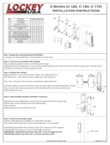
E-2 Select the LectroBolt (screw with red sleeve) length that corresponds
to the correct door thickness as noted in this chart:
LectroBolt
here
Mounting screws
LectroBolt
screw
HT
L
J
J
K
GF
This addendum replaces the existing Section E in your E-Plex 5000
Cylindrical Installation Instructions.
E. INSTALLING & HANDING THE INSIDE UNIT ASSEMBLY
Note: Installing levers to the unit assemblies before mounting them may
ease initial installation.
Door Thickness LectroBolt Size Mounting Screws Size
13⁄8" to 11⁄2"2
3⁄8"2
1⁄2"
(35 mm to 38 mm) (60 mm) (64 mm)
15⁄8" to 2" 2 3⁄4"2
7⁄8"
(41 mm to 51 mm) (70 mm) (73 mm)
21⁄8" to 2 1⁄4"3" 3
1⁄4"
(54 mm to 57 mm) (76 mm) (83 mm)
R
E-1
Inside Face of Plate
Remove screws and rotate this plate
inside face out to change from left hand
to right hand. There should be an “R” for
“Right Hand” stamped on the inside face.
Reinstall screws.
Inside Housing set
up for LEFT HAND
Inside Housing set up
for RIGHT HAND
R
E-3 Insert spindle (F) into
the hole (G) as shown
below until it “snaps”
into place. Place the
outside trim (K) onto
the door, inserting the
spindle (F) into the
hole in the door (H).
Put the thumbturn (T)
in a vertical position
and place the trim
assembly on the door
so that the spindle (F)
engages the thumbturn.
Ensure the red collar (J) is seated into its mounting hole. Carefully
push the inside housing (L) flush against the door.
Warning: If using a power drill, please be careful not to over-tighten as
this could cause damage to the mounting screws and threads.
E-4 Insert LectroBolt through the red inside
housing hole marked with the lightening
bolt symbol.
For now, only partially tighten the
LectroBolt to keep the red
collars in position.
Then, insert and tighten the other three
mounting bolts.
Finish tightening the LectroBolt to
secure the lock on the door.
-
 1
1
-
 2
2
Ask a question and I''ll find the answer in the document
Finding information in a document is now easier with AI
Related papers
Other documents
-
Dormakaba kaba E-Plex 7900 Installation guide
-
Grandeur WINFGRVER-70-TB Installation guide
-
Schlage L-SERIES User manual
-
Rockwell SAVOY Installation guide
-
Schlage FA360, FA362, FA393 Installation guide
-
ALLEGION Olivari PT Series Installation guide
-
 Grip Tight Tools HDGR3ED03-4 Installation guide
-
Rockwell H435 Installation guide
-
Hager 3800 Series Installation guide
-
 LOCKEY C-Series Keyless Entry Sliding Installation guide


