Page is loading ...

Continuous Gamma Level System
Installation Guide
PN 1-0702-
040
LevelPRO Measurement Systems


LevelPRO Measurement Systems
Continuous Gamma Level System
Installation Guide
PN 1-0702-040


© 2014 Thermo Fisher Scientific Inc. All rights reserved.
“Microsoft” and “Windows” are either trademarks or registered trademarks of Microsoft Corporation in the United States
and/or other countries. “HART” is a registered trademark of the HART Communication Foundation.
“FOUNDATION fieldbus” and “Fieldbus Foundation” are registered trademarks of Fieldbus Foundation.
“National Instruments” is a registered trademark of National Instruments Corporation.
All other trademarks are the property of Thermo Fisher Scientific Inc. and its subsidiaries.
Thermo Fisher Scientific Inc. (Thermo Scientific) makes every effort to ensure the accuracy and completeness of this
manual. However, we cannot be responsible for errors, omissions, or any loss of data as the result of errors or omissions.
Thermo Scientific reserves the right to make changes to the manual or improvements to the product at any time without
notice.
The material in this manual is proprietary and cannot be reproduced in any form without expressed written consent from
Thermo Scientific.


Thermo Scientific LevelPRO Installation Manual v
Revision History
Revision Level Date Comments
A 06-2014 Initial Release per ERO 8452


Contents
Safety Information & Guidelines ...................................................................................................... ix
Safety Considerations ......................................................................................................................... ix
Warnings, Cautions & Notes ............................................................................................................... x
Introduction ......................................................................................................................................... 1-1
Product Overview .............................................................................................................................. 1-1
Configurations ............................................................................................................................. 1-2
The Source ................................................................................................................................... 1-2
The Detector – Transmitter ......................................................................................................... 1-2
Functional Description ...................................................................................................................... 1-2
Communications & Measurement Software ............................................................................. 1-3
EZ Cal II Software Configuration ................................................................................................ 1-3
Multiple Readouts ....................................................................................................................... 1-3
Input & Output Signals ................................................................................................................ 1-4
Associated Documentation .............................................................................................................. 1-4
Handling, Storage & Shipping ......................................................................................................... 2-1
ESD Procedures ................................................................................................................................. 2-1
Unpacking, Inspection & Storage .................................................................................................... 2-2
Installation ........................................................................................................................................... 3-1
General .............................................................................................................................................. 3-1
Licensing............................................................................................................................................ 3-1
Guidelines ......................................................................................................................................... 3-2
General ......................................................................................................................................... 3-2
Mounting ........................................................................................................................................... 3-2
Source-Detector Configurations ................................................................................................. 3-3
Mounting Instructions ................................................................................................................. 3-3
Alignment ..................................................................................................................................... 3-4
Measureable Range .................................................................................................................... 3-5
Top of Range ........................................................................................................................... 3-5
Bottom of Range ..................................................................................................................... 3-5
The Source Housing .......................................................................................................................... 3-7
Shutter Actuator .......................................................................................................................... 3-8
Fan Beam Source Guidelines ...................................................................................................... 3-8
Multiple Detectors / Source Housings ....................................................................................... 3-9
System PCAs ..................................................................................................................................... 3-9
LevelPRO .................................................................................................................................... 3-10
LevelPRO-T ................................................................................................................................. 3-12
Remote Detector ................................................................................................................... 3-12
Transmitter ............................................................................................................................ 3-14
Wiring ................................................................................................................................................... 4-1
Preparation ........................................................................................................................................ 4-1
LevelPRO Wiring Procedures ............................................................................................................ 4-2
Chapter 1
Chapter 2
Chapter 3
Chapter 4
Thermo Scientific LevelPRO Installation Manual vii

Power Supply Wiring ........................................................................................................................ 4-3
Protective Earth Ground .............................................................................................................. 4-3
Safety Disconnect Mains Requirements .................................................................................... 4-3
DC Power ..................................................................................................................................... 4-3
AC Power ..................................................................................................................................... 4-4
Serial Communications ..................................................................................................................... 4-4
RS232 Wiring ............................................................................................................................... 4-5
RS485 Wiring ............................................................................................................................... 4-6
RS485 Detector to Transmitter Wiring .................................................................................. 4-7
Initial Setup for Party-Line Communications ........................................................................ 4-7
Standard Wiring ................................................................................................................................ 4-7
USB ............................................................................................................................................... 4-7
Ethernet ........................................................................................................................................ 4-7
Voltage Output ............................................................................................................................. 4-8
LevelPRO ................................................................................................................................. 4-8
LevelPRO-T .............................................................................................................................. 4-8
Current Output ............................................................................................................................. 4-9
Voltage Input ............................................................................................................................... 4-9
Current Input .............................................................................................................................. 4-10
LevelPRO ............................................................................................................................... 4-10
LevelPRO-T ............................................................................................................................ 4-10
Relay Outputs ............................................................................................................................ 4-10
Contact Closure (Digital) Inputs ................................................................................................ 4-11
Temperature Compensation ...................................................................................................... 4-11
Wiring the Optional ISIO Boards .................................................................................................... 4-12
Current Output ........................................................................................................................... 4-12
HART® Communications ............................................................................................................ 4-14
FOUNDATION™ Fieldbus Communications .................................................................................. 4-16
Support.................................................................................................................................................. 5-1
Contact Information .......................................................................................................................... 5-1
Warranty............................................................................................................................................ 5-2
Ordering Information ........................................................................................................................ A-1
Specifications .................................................................................................................................... B-1
Drawings ............................................................................................................................................. C-1
Risk Assessment ............................................................................................................................... D-1
Chapter 5
Appendix A
Appendix B
Appendix C
Appendix D
viii LevelPRO Installation Manual Thermo Scientific

Safety Information & Guidelines
All persons installing, using or maintaining this equipment must read and understand
the information contained in this section.
Safety
Considerations
Failure to follow appropriate safety procedures and/or inappropriate use of the
equipment described in this manual can lead to equipment damage or injury to
personnel.
Any person working with or on the equipment described in this manual is required to
evaluate all functions and operations for potential safety hazards before commencing
work. Appropriate precautions must be taken as necessary to prevent potential damage
to equipment or injury to personnel.
The information in this manual is designed to aid personnel in correctly and safely
installing, operating, and/or maintaining the system described; however, personnel are
still responsible for considering all actions and procedures for potential hazards or
conditions that may not have been anticipated in the written procedures. If a
procedure cannot be performed safely, it must not be performed until appropriate
actions can be taken to ensure the safety of the equipment and personnel. The
procedures in this manual are not designed to replace or supersede required or
common sense safety practices. All safety warnings listed in any documentation
applicable to equipment and parts used in or with the system described in this manual
must be read and understood prior to working on or with any part of the system.
Caution: Using this equipment in a manner not specified by Thermo
Scientific may impair the protective features provided by the product, leading
to equipment damage and/or personnel injury.
Thermo Scientific LevelPRO Installation Manual ix

Safety Information & Guidelines
Warnings, Cautions & Notes
Warnings,
Cautions &
Notes
The following admonitions are used throughout this manual to alert users to potential
hazards or important information. Failure to heed the warnings and cautions in this
manual can lead to injury or equipment damage.
Warning: The triangular icon displayed with a warning advises the user about
the type of hazard covered by the warning. See the table below for the types of
warning symbols used in this manual.
Table 1. Warning Symbols
Symbol Warning Type Description
General
Notifies users of procedures, practices,
conditions, etc., which may result in
injury or death if not carefully observed
or followed.
Electrical Safety
Notifies users of procedures, practices,
conditions, etc., which involve
electrical circuitry and may result in
injury or death if not carefully observed
or followed.
Ionizing Radiation
Notifies users of procedures, practices,
conditions, etc., where ionizing
radiation may be present and may
result in health issues or death if not
carefully observed or followed.
Caution: Cautions notify users of operating procedures, practices, conditions,
etc. which may result in equipment damage if not carefully observed or
followed.
Note: Notes emphasize important or essential information or a statement of
company policy regarding an operating procedure, practice, condition, etc.
x LevelPRO Installation Manual Thermo Scientific

Chapter 1
Introduction
Product
Overview
Thermo Scientific designed the family of LevelPRO measurement systems to provide
reliable, accurate level measurements for a wide variety of challenging applications. The
level detector, which mounts to the outside of the process vessel never contacts the
process material and can measure the process level in any vessel.
Each detector can convert the basic level measurement into a variety of output values
as appropriate for specific applications.
The system consists of up to two basic elements: the source head, which contains the
radioisotope source; the detector, which converts the incident radiation to a useable
electronic signal; and optional transmitter which displays the level value.
The radioisotope source emits gamma radiation, which passes through the vessel wall
and the process material before arriving at the detector. The detector then measures the
level of arriving radiation to determine the level of the process material. The amount of
radiation that reaches the detector varies inversely with the level of the process material.
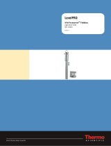
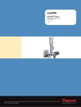
Figure 1-1. LevelPRO Measurement System
Thermo Scientific LevelPRO Installation Manual 1-1

Introduction
Product Overview
Configurations The Thermo Scientific LevelPRO level detector consolidates the detector function and
the detector to form an integrated system.
The LevelPRO-T provides the user with a separate transmitter unit.
Note: For the purposes of this manual, instructions referring only to the
LevelPRO should be considered applicable to the entire family of
LevelPRO/LevelPRO-T measurement systems. Any installation instructions
that apply exclusively to the LevelPRO-T will be specifically called out within
the text.
The Source A Cesium (Cs-137) radioisotope source is used to provide the gamma radiation field
for most applications. A Cobalt (Co-60) source is available for applications requiring a
higher energy source – typically those with very thick-walled vessels. The source
capsule secures the radioisotope inside a glass matrix and then double encapsulates the
glass in a pair of sealed stainless steel capsules, ensuring extreme resistant to vibration
and mechanical shock.
The source head, a lead-filled, welded steel housing, further encloses the source
capsule. A shaped opening in the lead shielding directs the gamma radiation beam
through the process material towards the detector. For most level applications, the
source is designed to produce a fan beam. Outside of the beam path, the energy
emitted from the source head is very low and well within prescribed limits.
Closing the source shutter blocks the radiation, attenuating the energy in the beam
path and allowing for safe handling, installation or servicing of the detector. All source
housings meet or exceed the safety requirements of regulatory agencies such as the U.S.
Nuclear Regulatory Commission (NRC), agreement states, the Canadian Nuclear
Safety Commission and local regulatory agencies in other countries. Please refer to the
Gamma Radiation Safety Guide (p/n 717904) for more radiation safety information.
The Detector –
Transmitter
The transmitter function in the LevelPRO system is incorporated into the detector
housing to create an integrated system, while in the LevelPRO-T system the
transmitter is a separate enclosure.
The LevelPRO measurement system uses a PVT scintillation detector to measure the
radiation reaching the detector from the source. The detector consists of a PVT
scintillator and a photomultiplier tube with the associated electronics. When gamma
radiation strikes the scintillation material, small flashes of light are emitted. As the level
of the process material increases, more gamma radiation is attenuated by the process
material, which allows fewer gamma rays to reach the detector and generates fewer
light pulses. The photomultiplier tube and associated detector electronics convert the
light pulses into electrical pulses that are processed by electronics in the detector of the
integrated unit or transmitter to determine the process material level and related
measurement values.
1-2 LevelPRO Installation Manual Thermo Scientific

Introduction
Functional Description
Functional
Description
Communications &
Measurement
Software
There are various communications options available with the LevelPRO measurement
system.
Using a PC with the Thermo Scientific communication software allows serial data
communication with the detector via the RS485 or the RS232 serial ports.
The HART® communication protocol is supported over the 4–20 mA current output.
Communication with the detector takes place through an Emerson Electric Co. field
communicator, Model 275 or newer, or any other compatible device containing the
appropriate device descriptors. LevelPRO systems equipped with the HART
communication option are supported on the Emerson Electric Co. Asset Management
System (AMS).
With the FOUNDATION™ fieldbus communication option, the LevelPRO system
provides users with access to control or program parameters via a host system. The
FOUNDATION fieldbus communication option is FISCO-qualified.
LevelPRO systems equipped with the Profibus PA communication option provide
users with access to control or program parameters via a host system.
Upon completion of detector setup, any present level measurement appears on the
external display.
Note: The HART, FOUNDATION fieldbus, and Profibus PA communication
options are not available on the beta versions of the LevelPRO systems.
EZ Cal II Software
Configuration
The LevelPRO comes with the Windows-based EZ Cal II configuration software. This
program allows you to construct a detector configuration file for a specific application,
and either upload it immediately to a connected detector, or store it on your
Windows-based PC for later implementation. The EZ Cal II software includes a
configuration wizard, significantly simplifying the detector configuration process.
Alternately, the EZ Cal II program also provides direct access to a wide range of
configuration and troubleshooting tools.
Multiple Readouts The LevelPRO detectors can provide a local readout of Level parameters, either by
adding an optional local display to the LevelPRO or through the LCD display built
into the transmitter of the LevelPRO-T. For those applications where it may be
advantageous to display the Level parameters in different units, both types of display
can accommodate up to four values.
Thermo Scientific LevelPRO Installation Manual 1-3

Introduction
Associated Documentation
Input & Output
Signals
Any process measurement can be assigned to the 4–20 mA current output, or the
measurement values can be read using a ModBus master host. The two contact closure
inputs can be used to activate many system commands based on a user-provided switch
input.
Associated
Documentation
Along with this guide, all persons installing, using or maintaining this equipment must
read and understand the following documents:
– Gamma Radiation Safety Guide, p/n 717904
– LevelPRO Foundation Fieldbus Application Guide (for units with Foundation
fieldbus installed)
– (pending) LevelPRO / LevelPRO-T with HART Protocol Interface Operation
Guide (for units using HART protocol)
1-4 LevelPRO Installation Manual Thermo Scientific

Chapter 2
Handling, Storage & Shipping
This chapter addresses procedures for handling electrostatic discharge (ESD) sensitive
equipment, as well as procedures for unpacking, inspecting, and storing of the system.
Caution: This system is an ESD sensitive instrument. Use proper ESD
protective equipment and procedures. Failure to comply with ESD procedures
can result in circuit damage.
ESD Procedures The instrument contains electronic components that can be damaged from discharges
of static electricity. Ordinarily, handling the circuit boards by their edges will not
damage the circuits.
Caution: Do not touch the circuit board components.
Observe the following when installing, setting up, servicing, troubleshooting or
repairing the instrument:
1. Use an antistatic bag. Most instrument subassemblies ship in a special antistatic
bag. When not installed, keep the assembly in the bag as often as possible.
2. Remove ESD-sensitive subassemblies only under the following conditions:
a. When standing at a designated static-free workstation, or when the bag is
grounded at a field site.
b. After the conductive area of the container has been neutralized.
c. After making firm contact with an antistatic mat and/or firmly gripping a
grounded individual.
3. Personnel handling ESD-sensitive devices should be neutralized to a static-free
workstation by means of a grounding wrist strap connected to the station or to a
good grounding point at the field site.
4. Do not allow clothing to make contact with ESD sensitive devices.
Thermo Scientific LevelPRO Installation Manual 2-1

Handling, Storage & Shipping
Unpacking, Inspection & Storage
5. Avoid touching edge connectors and components.
6. Avoid partially connecting ESD-sensitive devices. Floating leads can damage these
devices, especially the power supply connector.
7. Ground all test equipment.
8. Avoid static charges during troubleshooting.
Unpacking,
Inspection &
Storage
All personnel involved in the packing, shipping, or receiving of hazardous material
must be trained in accordance with the United States Department of Transportation
(DOT) and OSHA hazardous materials regulations or in accordance with the
Canadian Nuclear Safety Commission (CNSC) regulations.
Note: Inspection, adjustment, installation, and maintenance of the instrument
must be performed by experienced personnel only.
2-2 LevelPRO Installation Manual Thermo Scientific

Chapter 3
Installation
Read the Gamma Radiation Safety Guide (p/n 717904) prior to installing the
equipment.
Copies of drawings referenced in this manual are provided in Appendix C.
General Refer to the table below for the components of the various Thermo Scientific
LevelPRO measurement systems.
Note: The combination of the detector-transmitter and the source head is
referred to as the detector.
Table 3-1. LevelPRO Measurement System Components
Component LevelPRO LevelPRO-T
Detector-Transmitter MS2011LU N/A
Detector N/A MS2011LUR
Transmitter N/A MS2011T
Source Head 5205,5206,5207,5208,5210
Licensing Warning: The instrument is a nuclear device regulated by federal and/or state
authorities. The user is responsible for knowing and following the pertinent
safety and regulatory requirements. Refer to the Gamma Radiation Safety
Guide (p/n 717904) for a summary of these requirements.
Warning: Installation and commissioning of Thermo Scientific source heads
requires a licensed operator. In the United States, a general license permits the
licensee to own and install all of the instrument’s components, including the
source head. However, a specific license authorizing radiation commissioning
is required to commission the instrument by removing the lock and opening
the source-housing shutter for the first time. In Canada, only those who
possess a CNSC license with a condition authorizing the
mounting/dismounting of devices may remove the instrument from the
shipping container. For assistance obtaining a license or
commissioning/decommissioning the instrument, contact Thermo Scientific.
Thermo Scientific LevelPRO Installation Manual 3-1

Installation
Mounting
Guidelines Warning: Do not install the system in any hazardous area other than those
approved. Refer to the equipment tag for the specific approvals applicable to
the configuration of your instrument.
Warning: Do not apply power to the instrument in any hazardous area unless
the safety ground is properly wired inside the instrument and the cover is
properly installed.
General Review the following guidelines when planning detector installation.
1. Correct power source for the detector:
a. 11 – 32 VDC, 770 mA max, at detector input
b. 100 to 240 VAC, 50/60 Hz, 300 mA max (with AC power option)
2. Operating temperature range: -40°C to 75°C (-40°F to 167°F)
3. Ensure enough clearance exists to install and service the detector. Refer to the
appropriate drawings for your type of detector and mount (Appendix C).
4. Position the detector so that the radioactive source identification tag is visible. The
source housing tag should be upright.
Note: Do not paint or overcoat the source housing without first masking its
identification tag and other labeling. All labels on the source housing must
remain visible.
5. Do not mount the detector should where process overflow or other material can
collect in the beam path. The source shutter mechanism must be kept free of
debris.
Caution: Do not place your hand between the source and the vessel wall. Use a
brush or other tool to remove accumulated debris.
Mounting Warning: Installation must be in accordance with local and national electric
codes for the area classifications.
Warning: The handle of the source housing must be in the OFF position
during installation.
Warning: Do not reach inside the source housing at any time during
installation.
Warning: Use proper lifting procedures during installation to avoid injury.
3-2 LevelPRO Installation Manual Thermo Scientific
/