Thermo Fisher Scientific LevelPRO User guide
- Category
- Measuring, testing & control
- Type
- User guide

Part of Thermo Fisher Scientific
LevelPRO
Continuous Gamma Level System
User Guide
P/N 717778
Revision F


LevelPRO
Continuous Gamma Level System
User Guide
P/N 717778
Revision F


©2011 Thermo Fisher Scientific Inc. All rights reserved.
“Microsoft” and “Windows” are either registered trademarks or trademarks of Microsoft Corporation in the
United States and/or other countries.
“HART” is a registered trademark of the HART Communication Foundation.
“Fisher-Rosemount” is either a trademark or registered trademark of Emerson Electric Company.
“FOUNDATION fieldbus” and “Fieldbus Foundation” are registered trademarks of Fieldbus
Foundation.
All other trademarks are the property of Thermo Fisher Scientific Inc. and its subsidiaries.
Thermo Fisher Scientific Inc. (Thermo Fisher) makes every effort to ensure the accuracy and completeness of this
manual. However, we cannot be responsible for errors, omissions, or any loss of data as the result of errors or
omissions. Thermo Fisher reserves the right to make changes to the manual or improvements to the product at
any time without notice.
The material in this manual is proprietary and cannot be reproduced in any form without expressed written
consent from Thermo Fisher.

This page intentionally left blank.

Thermo Fisher Scientific LevelPRO User Guide v
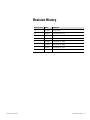
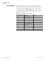
Revision History
Revision Level Date Comments
1.0 03-1999 Initial release.
2.0 08-2001 Revised per ECO 7570.
A 02-2006 Revised per ECO 5101.
B 10-2007 Revised per ECO 6000.
C 05-2008 Revised per ECO 6366.
D 05-2009 Revised per ECO 6940.
E 04-2010 Revised per ECO 7323.
F 12-2011 Revised per ECO 7875.

This page intentionally left blank.

Thermo Fisher Scientific LevelPRO User Guide vii
Contents
Safety Information & Guidelines ..................................................................... xi
Safety Considerations ............................................................................. xi
Warnings, Cautions, & Notes ................................................................ xi
Product Overview ............................................................................................. 1-1
Introduction ........................................................................................ 1-1
Source .............................................................................................. 1-1
Detector-Transmitter ....................................................................... 1-2
Functional Description ....................................................................... 1-2
Communications & Measurement Display ...................................... 1-2
Inputs & Outputs ............................................................................ 1-3
Other Features .................................................................................... 1-4
Dynamic Menu System .................................................................... 1-4
Instantaneous Response .................................................................... 1-4
Built-In Volume Measurement ........................................................ 1-4
Multiple Readouts ............................................................................ 1-4
Process Alarms ................................................................................. 1-4
Fault Detection ................................................................................ 1-4
Required Documentation .................................................................... 1-5
Getting Started................................................................................................... 2-1
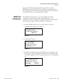
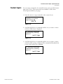
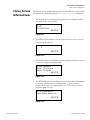
Communications Setup ....................................................................... 2-1
Serial ................................................................................................ 2-1
HART .............................................................................................. 2-2
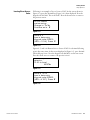
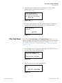
Gauge Operation ................................................................................ 2-2
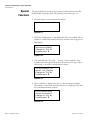
The Measurement Display ............................................................... 2-2
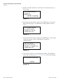
Entering Data .................................................................................. 2-3
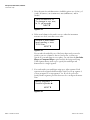
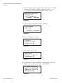
The Setup Menus ............................................................................. 2-4
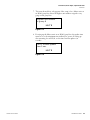
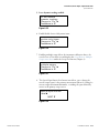
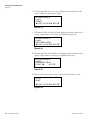
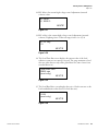
The Direct Access Method ............................................................... 2-4
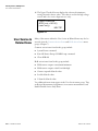
Resetting Factory Defaults ............................................................... 2-6
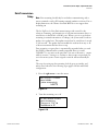
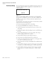
Additional Menu Items .................................................................... 2-6
Saving Entries .................................................................................. 2-6
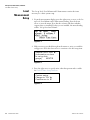
Set up Level, Level Alarms, & Volume .......................................................... 3-1
Level Measurement Setup ................................................................... 3-2
Multiple Setups ................................................................................ 3-5
Alarm Setup ........................................................................................ 3-6
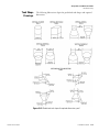
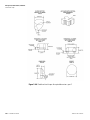
Tank Volume Setup ............................................................................ 3-9
Other Tank Shapes ........................................................................ 3-13
Chapter 1
Chapter 2
Chapter 3

Contents
viii LevelPRO User Guide Thermo Fisher Scientific
Tank Shape Drawings .................................................................... 3-19
Background Measurements ............................................................... 3-21
Standardization & Calibration .......................................................... 3-22
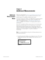
Additional Measurements ............................................................................... 4-1
Additional Measurements Menu ......................................................... 4-1
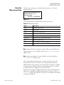
Select the Measurement Type ........................................................... 4-3
Set Up Alarms for Additional Measurements ...................................... 4-8
Display the Additional Measurement .................................................. 4-8
Display Scaling .................................................................................... 4-9
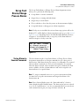
Gauge Fine Tuning ............................................................................................ 5-1
Time Constant Setup .......................................................................... 5-1
Sensor Head Standardization .............................................................. 5-4
Procedure ......................................................................................... 5-5
Service Only Items ........................................................................... 5-8
Level Gauge Calibration ...................................................................... 5-9
General ............................................................................................ 5-9
Why Separate Standardization & Calibration ................................. 5-10
The Procedure ................................................................................ 5-10
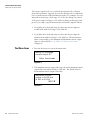
Current Output & Alarm Setup ........................................................................ 6-1
Modify/ Reassign Current Output ...................................................... 6-1
Overview .......................................................................................... 6-1
The Menu Items .............................................................................. 6-2
Set up Fault Alarms/Change Process Alarms ....................................... 6-5
Set up Alarms to Execute Commands .............................................. 6-5
Assign Relays to Warning & Fault Alarms ...................................... 6-11
Assign Relays to Mode Alarms ....................................................... 6-14
Show Relay Status .......................................................................... 6-17
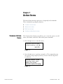
Action Items ....................................................................................................... 7-1
Common Action Items ....................................................................... 7-1
Alarm Action Items ............................................................................. 7-3
Hold Action Items .............................................................................. 7-5
Serial Port Action Items ...................................................................... 7-8
Serial Ports, Contact Inputs, & Special Functions ..................................... 8-1
Serial Ports .......................................................................................... 8-1
Terminal Types ................................................................................ 8-2
Party-Line Communications ............................................................ 8-2
Modify Port Configuration .............................................................. 8-5
Data Transmission Setup ................................................................. 8-7
Data Format Setup ......................................................................... 8-10
Chapter 4
Chapter 5
Chapter 6
Chapter 7
Chapter 8

Contents
Thermo Fisher Scientific LevelPRO User Guide ix
Contact Inputs .................................................................................. 8-11
Special Functions .............................................................................. 8-12
Custom Units Messages ................................................................. 8-14
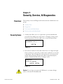
Security, Service, & Diagnostics ................................................................... 9-1
Overview ............................................................................................. 9-1
Security Items ..................................................................................... 9-1
Diagnostics ......................................................................................... 9-3
The Snapshot Menu ......................................................................... 9-6
User Service & Related Items ............................................................ 9-10
Factory Service & Related Items ........................................................ 9-11
Testing Relays ................................................................................ 9-14
Signal Diagnostics .......................................................................... 9-15
Maintenance .................................................................................................... 10-1
Overview ........................................................................................... 10-1
Shutter Check ................................................................................... 10-1
Tag & Label Check ........................................................................... 10-1
The Source Housing ......................................................................... 10-2
Gauge Calibration Check .................................................................. 10-2
Leak Tests ......................................................................................... 10-2
Troubleshooting & Service ........................................................................... 11-1
The Scintillation Detector ................................................................. 11-1
The Current Board ........................................................................... 11-2
The Relay .......................................................................................... 11-2
Level Indication ................................................................................ 11-3
Equipment Required ...................................................................... 11-3
Site Preparation .............................................................................. 11-3
Procedure ....................................................................................... 11-4
Recorded Values ............................................................................. 11-8
Communication Problems ................................................................ 11-2
Contact Information ......................................................................... 11-9
Warranty ........................................................................................... 11-9
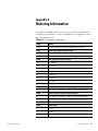
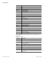
Ordering Information ....................................................................................... A-1
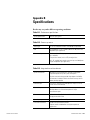
Specifications................................................................................................... B-1
Special Measurement Codes ......................................................................... C-1
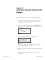
Calibration when Vessel Cannot Be Emptied ............................................ D-1
Chapter 9
Chapter 10
Chapter 11
Appendix A
Appendix B
Appendix C
Appendix D

Contents
x LevelPRO User Guide Thermo Fisher Scientific
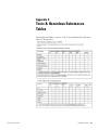
Toxic & Hazardous Substances Tables ....................................................... E-1
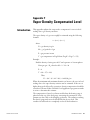
Vapor Density Compensated Level ................................................................ F-1
Introduction ........................................................................................ F-1
Finding a Compensation Formula ....................................................... F-2
Special Equation ................................................................................. F-3
Gauge Setups ...................................................................................... F-4
Wiring ................................................................................................ F-5
X-ray Safeguard Software Setup .................................................................. G-1
Overview ............................................................................................ G-1
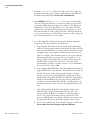
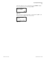
Setup .................................................................................................. G-1
Related Technical Bulletins .......................................................................... H-1
Index .......................................................................................................... INDEX-1
Appendix E
Appendix F
Appendix G
Appendix H

Thermo Fisher Scientific LevelPRO User Guide xi
Safety Information & Guidelines
This section contains information that must be read and understood by all
persons installing, using, or maintaining this equipment.
Failure to follow appropriate safety procedures or inappropriate use of the
equipment described in this manual can lead to equipment damage or
injury to personnel.
Any person working with or on the equipment described in this manual is
required to evaluate all functions and operations for potential safety hazards
before commencing work. Appropriate precautions must be taken as
necessary to prevent potential damage to equipment or injury to personnel.
The information in this manual is designed to aid personnel to correctly
and safely install, operate, and/or maintain the system described; however,
personnel are still responsible for considering all actions and procedures for
potential hazards or conditions that may not have been anticipated in the
written procedures. If a procedure cannot be performed safely, it must not
be performed until appropriate actions can be taken to ensure the safety
of the equipment and personnel. The procedures in this manual are not
designed to replace or supersede required or common sense safety practices.
All safety warnings listed in any documentation applicable to equipment
and parts used in or with the system described in this manual must be read
and understood prior to working on or with any part of the system.
Failure to correctly perform the instructions and procedures in this
manual or other documents pertaining to this system can result in
equipment malfunction, equipment damage, and/or injury to personnel.
The following admonitions are used throughout this manual to alert users
to potential hazards or important information. Failure to heed the
warnings and cautions in this manual can lead to injury or equipment
damage.
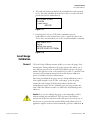
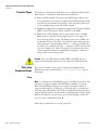
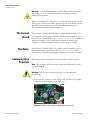
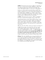
Warning Warnings notify users of procedures, practices, conditions, etc.
which may result in injury or death if not carefully observed or followed.
The triangular icon displayed with a warning may contain a lightning bolt
or the radiation symbol, depending on the type of hazard.
Safety
Considerations
Warnings,
Cautions, &
Notes

Safety Information & Guidelines
Warnings, Cautions, & Notes
xii LevelPRO User Guide Thermo Fisher Scientific
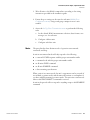
Caution Cautions notify users of operating procedures, practices,
conditions, etc. which may result in equipment damage if not carefully
observed or followed.
Note Notes emphasize important or essential information or a statement of
company policy regarding an operating procedure, practice, condition,
etc.

Thermo Fisher Scientific LevelPRO User Guide 1-1
Chapter 1
Product Overview
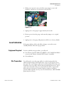
The Thermo Scientific LevelPRO continuous gamma level system is
designed to provide reliable, accurate level and volume measurements for
even the most challenging applications. The gauge is mounted on the
outside of the process vessel and never contacts the process material.
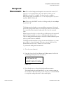
The gauge consists of the source head that contains the radioisotope source
and the detector-transmitter that contains the scintillator detector and
electronics. The radioisotope source emits gamma radiation that passes
through the process material. The detector measures the energy of the
radiation arriving at the detector after passing through the process material
(and vessel walls). The gauge determines the level of the process material by
measuring the amount of radiation arriving at the detector, which varies
with the level of the process material.
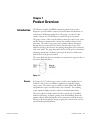
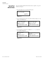
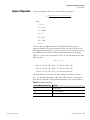
The source head and detector-transmitter are mounted on opposite sides of
the tank as illustrated below.
Figure 1–1.
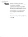
A Cesium (Cs-137) radioisotope source is used for most applications. A
Cobalt (Co-60) source is available for applications requiring a higher
energy source. The radioisotope is bound in ceramic pellets and double
encapsulated in a pair of sealed stainless steel containers. The resulting
source capsule is highly resistant to vibration and mechanical shock.
The source capsule is further enclosed in the source head, a lead-filled,
welded steel housing. A shaped opening in the lead shielding directs the
gamma radiation beam through the process material towards the detector.
Outside of the beam path, the energy escaping the source head is very low
and well within prescribed limits.
Introduction
Source

Product Overview
Functional Description
1-2 LevelPRO User Guide Thermo Fisher Scientific
Closing the source shutter allows the beam to be turned off (the shutter
blocks the radiation) during installation or servicing of the gauge. All
source housings meet or exceed the safety requirements of the U.S. Nuclear
Regulatory Commission (NRC) and Agreement State regulations. Refer to
the Gamma Radiation Safety Guide (p/n 717904).
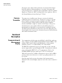
The gauge uses a scintillator-type detector to measure the radiation
reaching the detector from the source. The detector consists of a special
plastic scintillator material and a photomultiplier tube (PMT) with the
associated electronics. When radiation strikes the plastic scintillator
material, small flashes of light are emitted. As the density of the process
material increases, more gamma radiation is absorbed by the process
material and fewer light pulses are generated by the scintillator material.
The PMT and associated detector electronics convert the light pulses into
electrical pulses that are processed to determine the process material density
and related measurement values.
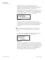
You communicate with the gauge via the RS485 or the RS232 serial ports
using a Thermo Scientific Model 9734 Handheld Terminal (HHT), a PC
running TMTComm for Microsoft Windows or other terminal
emulation software, or a standard ANSI or VT-100 terminal.
The HART communication protocol is supported over the 4–20 mA
current output with an optional daughter board. Communication with the
gauge is through the HART 275 or 375 communicator. Refer to the
LevelPRO HART Operation Guide (p/n 717817) for instructions.
With the FOUNDATION™ fieldbus communication option, the LevelPRO
system provides users with access to control or program parameters via a
host system.
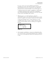
Once the gauge has been set up, the primary (level) measurement is
displayed on the external display, if present, and on the remote terminal or
HHT.
Detector
-
Transmitter
Functional
Description
Co
mmunications &
Measurement
Display

Product Overview
Functional Description
Thermo Fisher Scientific LevelPRO User Guide 1-3
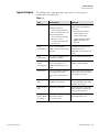
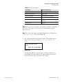
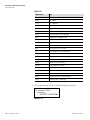
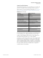
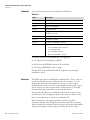
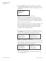
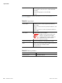
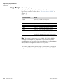
The characteristics of the input and output options for the gauge are
summarized in the table below.
Table 1–1.
Type Characteristics Comments
Current output 3.8–20.5 mA DC.
Standard configuration:
- Isolated, loop-powered, 24
Vdc input, 700 ohm max. load.
Alternate configurations:
- Non-isolated, self-powered,
700 ohm max. load.
- Isolated, self-powered, 700
ohm max. load.
Default range is 4–20 mA DC. One
current output is provided on the
CPU board.
To reconfigure current output:
- Move a jumper for non-
isolated, self-powered
- Add a piggyback board (p/n
886595) for isolated, self-
powered.
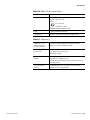
Serial
communications
RS232: one terminal block.
RS485: one terminal block and one
RJ11 jack.
Full duplex communication with
remote terminal or PC.
Half-duplex communication to PC
or HHT.
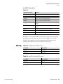
HART
communications
HART protocol supported over the
4–20 mA current output.
Optional daughter board required.
FOUNDATION
fieldbus
communications
The Device Description is a DD4
that is interpreted by a host
implementing DD Services 4.x or
higher.
The DD is available from the
Fieldbus Foundation website.
Optional relays Two relays optionally available on
the AC power/ relay board.
Form C SPDT, isolated, 8 A, 220
Vac.
Process alarms and system fault or
warning alarms can be assigned to
control (open/close) relays.
Contact closure
inputs
Two contact closure inputs are
provided on the CPU board.
Execute system commands based
on a user-provided contact switch
opening or closing input.
Auxiliary current
input
0–20 mA DC current input. Current input value can be used to
adjust the level measurement by
using the special equations.
Optional Thermo
Scientific Model
9723 display
Optional backlit LCD for
measurement readouts.
2-line x 16-character.
Up to four measurement readouts
can be displayed at a time.
Inputs & Outputs

Product Overview
Other Features
1-4 LevelPRO User Guide Thermo Fisher Scientific
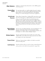
In addition to the functionality discussed above, the LevelPRO gauge has
the following features.
The setup menus enable you to quickly configure the gauge by requiring
you to enter all of the basic parameters. Additional menu groups contain
fields in which you can enter specialized parameters and commands,
allowing you to customize the gauge for a wide variety of applications.
Thermo Fisher’s Dynamic Process Tracking (DPT) ensures there is no lag
time in the system response to significant changes in process level. When
changes occur, the DPT feature reduces the normal averaging time
constant by a factor of eight, ensuring a rapid, smooth output response.
When the process stabilizes, a longer time constant is applied to reduce the
fluctuations inherent in radiation-based measurements. In this way, process
level changes are immediately reflected in the transmitter output, while the
effects of statistical variations in the radiation measurement are greatly
reduced.
Select from a list of predefined tank shapes, enter the tank dimensions, and
the gauge computes tank volume from an internal equation library.
Alternately, you can define volume as a polynomial expression based on the
level (height) or as a table of volume and height value pairs.
Select up to eight measurement values for display: level, volume, ullage
(unfilled volume), percent full, percent empty, percent level, mass, and the
rate of change of any of these measurements.
Define up to 16 process alarms in addition to the built-in system fault
alarms and warning alarms.
Automatic verification and error correction software continuously monitors
system operations. System faults can be programmed to trigger alarms.
Other Features
Dynamic Menu
System
Instantaneous
Response
Built-
In Volume
Measurement
Multiple Readouts
Process Alarms
Fault Detection

Product Overview
Required Documentation
Thermo Fisher Scientific LevelPRO User Guide 1-5
Along with this guide, the following documents must be read and
understood by all persons installing, using, or maintaining this equipment:
LevelPRO installation guide, p/n 717760
LevelPRO HART operation guide, p/n 717817 (if using HART)
Model 9734 HHT user guide, p/n 717797 (if using the HHT)
Gamma Radiation Safety Guide, p/n 717904
LevelPRO with FOUNDATION™ Fieldbus Application Guide, p/n
717915 (if FOUNDATION fieldbus option is installed)
Required
Documentation

This page intentionally left blank.
Page is loading ...
Page is loading ...
Page is loading ...
Page is loading ...
Page is loading ...
Page is loading ...
Page is loading ...
Page is loading ...
Page is loading ...
Page is loading ...
Page is loading ...
Page is loading ...
Page is loading ...
Page is loading ...
Page is loading ...
Page is loading ...
Page is loading ...
Page is loading ...
Page is loading ...
Page is loading ...
Page is loading ...
Page is loading ...
Page is loading ...
Page is loading ...
Page is loading ...
Page is loading ...
Page is loading ...
Page is loading ...
Page is loading ...
Page is loading ...
Page is loading ...
Page is loading ...
Page is loading ...
Page is loading ...
Page is loading ...
Page is loading ...
Page is loading ...
Page is loading ...
Page is loading ...
Page is loading ...
Page is loading ...
Page is loading ...
Page is loading ...
Page is loading ...
Page is loading ...
Page is loading ...
Page is loading ...
Page is loading ...
Page is loading ...
Page is loading ...
Page is loading ...
Page is loading ...
Page is loading ...
Page is loading ...
Page is loading ...
Page is loading ...
Page is loading ...
Page is loading ...
Page is loading ...
Page is loading ...
Page is loading ...
Page is loading ...
Page is loading ...
Page is loading ...
Page is loading ...
Page is loading ...
Page is loading ...
Page is loading ...
Page is loading ...
Page is loading ...
Page is loading ...
Page is loading ...
Page is loading ...
Page is loading ...
Page is loading ...
Page is loading ...
Page is loading ...
Page is loading ...
Page is loading ...
Page is loading ...
Page is loading ...
Page is loading ...
Page is loading ...
Page is loading ...
Page is loading ...
Page is loading ...
Page is loading ...
Page is loading ...
Page is loading ...
Page is loading ...
Page is loading ...
Page is loading ...
Page is loading ...
Page is loading ...
Page is loading ...
Page is loading ...
Page is loading ...
Page is loading ...
Page is loading ...
Page is loading ...
Page is loading ...
Page is loading ...
Page is loading ...
Page is loading ...
Page is loading ...
Page is loading ...
Page is loading ...
Page is loading ...
Page is loading ...
Page is loading ...
Page is loading ...
Page is loading ...
Page is loading ...
Page is loading ...
Page is loading ...
Page is loading ...
Page is loading ...
Page is loading ...
Page is loading ...
Page is loading ...
Page is loading ...
Page is loading ...
Page is loading ...
Page is loading ...
Page is loading ...
Page is loading ...
Page is loading ...
Page is loading ...
Page is loading ...
Page is loading ...
Page is loading ...
Page is loading ...
Page is loading ...
Page is loading ...
Page is loading ...
Page is loading ...
Page is loading ...
Page is loading ...
Page is loading ...
Page is loading ...
Page is loading ...
Page is loading ...
Page is loading ...
Page is loading ...
Page is loading ...
Page is loading ...
Page is loading ...
Page is loading ...
Page is loading ...
Page is loading ...
Page is loading ...
Page is loading ...
Page is loading ...
-
 1
1
-
 2
2
-
 3
3
-
 4
4
-
 5
5
-
 6
6
-
 7
7
-
 8
8
-
 9
9
-
 10
10
-
 11
11
-
 12
12
-
 13
13
-
 14
14
-
 15
15
-
 16
16
-
 17
17
-
 18
18
-
 19
19
-
 20
20
-
 21
21
-
 22
22
-
 23
23
-
 24
24
-
 25
25
-
 26
26
-
 27
27
-
 28
28
-
 29
29
-
 30
30
-
 31
31
-
 32
32
-
 33
33
-
 34
34
-
 35
35
-
 36
36
-
 37
37
-
 38
38
-
 39
39
-
 40
40
-
 41
41
-
 42
42
-
 43
43
-
 44
44
-
 45
45
-
 46
46
-
 47
47
-
 48
48
-
 49
49
-
 50
50
-
 51
51
-
 52
52
-
 53
53
-
 54
54
-
 55
55
-
 56
56
-
 57
57
-
 58
58
-
 59
59
-
 60
60
-
 61
61
-
 62
62
-
 63
63
-
 64
64
-
 65
65
-
 66
66
-
 67
67
-
 68
68
-
 69
69
-
 70
70
-
 71
71
-
 72
72
-
 73
73
-
 74
74
-
 75
75
-
 76
76
-
 77
77
-
 78
78
-
 79
79
-
 80
80
-
 81
81
-
 82
82
-
 83
83
-
 84
84
-
 85
85
-
 86
86
-
 87
87
-
 88
88
-
 89
89
-
 90
90
-
 91
91
-
 92
92
-
 93
93
-
 94
94
-
 95
95
-
 96
96
-
 97
97
-
 98
98
-
 99
99
-
 100
100
-
 101
101
-
 102
102
-
 103
103
-
 104
104
-
 105
105
-
 106
106
-
 107
107
-
 108
108
-
 109
109
-
 110
110
-
 111
111
-
 112
112
-
 113
113
-
 114
114
-
 115
115
-
 116
116
-
 117
117
-
 118
118
-
 119
119
-
 120
120
-
 121
121
-
 122
122
-
 123
123
-
 124
124
-
 125
125
-
 126
126
-
 127
127
-
 128
128
-
 129
129
-
 130
130
-
 131
131
-
 132
132
-
 133
133
-
 134
134
-
 135
135
-
 136
136
-
 137
137
-
 138
138
-
 139
139
-
 140
140
-
 141
141
-
 142
142
-
 143
143
-
 144
144
-
 145
145
-
 146
146
-
 147
147
-
 148
148
-
 149
149
-
 150
150
-
 151
151
-
 152
152
-
 153
153
-
 154
154
-
 155
155
-
 156
156
-
 157
157
-
 158
158
-
 159
159
-
 160
160
-
 161
161
-
 162
162
-
 163
163
-
 164
164
-
 165
165
-
 166
166
-
 167
167
-
 168
168
-
 169
169
-
 170
170
-
 171
171
-
 172
172
-
 173
173


Thermo Fisher Scientific LevelPRO User guide
- Category
- Measuring, testing & control
- Type
- User guide
Ask a question and I''ll find the answer in the document
Finding information in a document is now easier with AI
Related papers
-
 Thermo Fisher Scientific LevelPRO Installation guide
-
 Thermo Fisher Scientific LevelPRO User guide
-
 Thermo Fisher Scientific LevelPRO Measurement System Installation guide
-
 Thermo Fisher Scientific LevelPRO User manual
-
 Thermo Fisher Scientific InterFace Operating instructions
-
 Thermo Fisher Scientific Application User guide
-
 Thermo Fisher Scientific TMT Comm Communication Software User guide
-
 Thermo Fisher Scientific Application User guide
-
 Thermo Fisher Scientific SGD-O Gauge User manual
-
 Thermo Fisher Scientific SGD-O User guide


