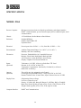
Ronan Engineering X96S Instructions And Operating Manual
- Category
- Measuring, testing & control
- Type
- Instructions And Operating Manual

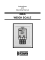
Instructions
and
Operating Manual
X96S
WEIGH SCALE
60%
Ronan Engineering
Main Menu
Variables
Status Display
Configuration
Digital Outputs
Digital Inputs
Auto Cal
Calibration

i
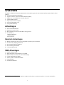
Table of Contents
OVERVIEW.........................................................................................................................1
Advantages.................................................................... 1
Gamma's Advantages..................................................................................................................................................... 1
X96S Advantages........................................................................................................................................................... 1
BASIC CONCEPTS ............................................................................................................2
Communications................................................................ 2
4-20 MA......................................................................................................................................................................... 2
HART............................................................................................................................................................................. 2
Variables..................................................................... 2
Communication Variables.............................................................................................................................................. 2
Device Variables............................................................................................................................................................ 2
Configuration Variables................................................................................................................................................. 3
THEORY .............................................................................................................................4
Theory of Radiation Gaging.................................................... 4
Principles of Operation....................................................... 5
PASSWORD.......................................................................................................................6
MENUS/OPERATION.........................................................................................................7
Menu Trees.................................................................... 7
Root Menu.................................................................... 12
Variables Menu............................................................................................................................................................ 12
Variable Mapping Menu .......................................................................................................................................... 12
Displays Menu ............................................................................................................................................................. 13
Status Display Menu .................................................................................................................................................... 13
Configuration Menu..................................................................................................................................................... 14
Operation Menu ....................................................................................................................................................... 14
Filtering Menu ..................................................................................................................................................... 15
Linearization Menu .............................................................................................................................................. 16
Config Linearize Menu .................................................................................................................................... 16
Scan Time Menu .................................................................................................................................................. 16
Rate Menu................................................................................................................................................................ 17
Weight Menu ........................................................................................................................................................... 18
Speed Menu ............................................................................................................................................................. 18
Head Temp Config Menu......................................................................................................................................... 19
Display Totalizer Menu ........................................................................................................................................... 19
Remote Totalizer Menu ........................................................................................................................................... 20
PD Counter Menu .................................................................................................................................................... 20
Alarms...................................................................................................................................................................... 21
Auto Reference Menu .............................................................................................................................................. 21
Hardware Menu ....................................................................................................................................................... 22
System Hardware Menu........................................................................................................................................... 22
Source Type Menu ................................................................................................................................................... 23
Usr Def Source Menu .......................................................................................................................................... 23

ii
Speed Hardware Menu............................................................................................................................................. 23
Analog Out Cnfg Menu............................................................................................................................................ 24
HART Menu ............................................................................................................................................................ 24
System Menu ........................................................................................................................................................... 24
Digital Outputs Menu......................................................... 25
Digital Inputs Menu.......................................................... 26
Input Menus ................................................................................................................................................................. 26
Calibration Menu............................................................. 27
Ref Constants Menu..................................................................................................................................................... 27
Calibrate Menu............................................................................................................................................................. 28
Low Reference (Calibrate) Menu............................................................................................................................. 28
High Calibrate (Calibrate) Menu ............................................................................................................................. 28
Cal Speed Menu........................................................................................................................................................... 28
Low Reference (Cal Speed) Menu ........................................................................................................................... 28
High Calibrate (Cal Speed) Menu............................................................................................................................ 29
Manual Entry (Cal Speed) Menu ............................................................................................................................. 29
Loop Config Menu....................................................................................................................................................... 29
Aux Loop Cfg Menu.................................................................................................................................................... 30
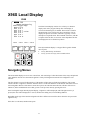
X96S LOCAL DISPLAY ...................................................................................................31
Navigating Menus............................................................. 31
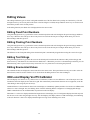
Editing Values............................................................... 32
Editing Fixed Point Numbers....................................................................................................................................... 32
Editing Floating Point Numbers................................................................................................................................... 32
Editing Text Strings ..................................................................................................................................................... 32
Editing Enumerated Values ......................................................................................................................................... 32
X96 Local Display Vs 275 Calibrator.......................................... 32
SOURCE INSPECTION AND INSTALLATION................................................................33
Safety Precautions........................................................... 33
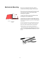
Mechanical Mounting.......................................................... 34
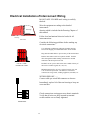
Electrical Installation of Interconnect Wiring............................... 35
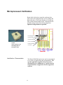
Microprocessor Verification.................................................. 36
Identification / Documentation .................................................................................................................................... 36
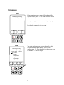
Power-up..................................................................... 37
PASSWORD.....................................................................................................................38
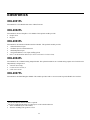
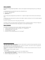
CALIBRATION .................................................................................................................39
Speed Low and High Calibration............................................... 39
Low Speed Reference .................................................................................................................................................. 39
High Speed Calibration................................................................................................................................................ 40
Speed Calibration with Line Down Contact ................................................................................................................ 41
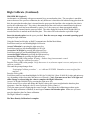
Mass Density Low/Reference and High/Calibration.............................. 42
Low Reference............................................................................................................................................................. 42
High Calibrate.............................................................................................................................................................. 43
Zero the totalizer ...................................................................................................................................................... 43
Pass a known amount of process through the Ronan X96S Weigh Scale ........................................................43
Calculate the new L.F. (Loading Factor) and input the value into the X96S ................................................... 44
CONFIGURATION............................................................................................................48

iii
DETECTOR ......................................................................................................................49
Scintillator Detector........................................................ 49
ION Chamber.................................................................. 51
ELECTRONICS ................................................................................................................55
X96-2001PL................................................................... 55
X96-2002PL................................................................... 55
X96-2003PL................................................................... 55
X96-2004PL................................................................... 55
X96-2007PL................................................................... 55
X96-2008PL................................................................... 56
X96-2009PL................................................................... 56
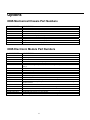
OPTIONS..........................................................................................................................57
X96S Mechanical Chassis Part Numbers......................................... 57
X96S Electronic Module Part Numbers.......................................... 57
REGULATIONS................................................................................................................59
DRAWINGS ......................................................................................................................60

1
Overview
The X96S is a family of measurement products that is intended to replace the current X96N and X99 product families. These
products:
• use nuclear measurement techniques,
• support all features of the current X96N and X99 products,
• support up to 32 scintillation or ionization detectors,
• optional HART interface,
• improved user interface options1,
• more user functionality, and
• more product flexibility.
Advantages
• Non-Contact Measurement
• Displays in Customer Units
• Most Applications can be solved with low-energy sources
• Not affected by:
-extreme temperatures
-caustic processes
-sterile processes
Gamma's Advantages
• Mounts external to the conveyor (no components exposed to process material)
• Not affected by changing belt tension
• Does not make material radioactive
• Does not change the material
• Can be shielded by lead
X96S Advantages
• HART Communications
• Identical interface on local display as via HART
• Blind transmitter in detector on self contained design
• Custom configuration of display
• Surface, panel or rack mount available
• Field mountable
• Push button calibration
1 This includes the ability to have a simple or complex user interface, a remote user interface, or even no user interface.

2
Basic Concepts
Communications
The Ronan X96S Weigh Scale provides both 4-20 mA current loop and HART communications.
4-20 MA
For many years, the field communication standard for process automation equipment has been a 4-20 mA current loop signal. The
current varies in proportion to the process variable being represented. In typical applications, a signal of 4mA will correspond to
the lower limit (0%) of the calibrated range and 20mA will correspond to the upper limit (100%) of the calibrated range. Thus, if
the system is calibrated for 0 to 4 pound per foot, then an analog current of 12mA (50% of range) will correspond to a weight of 2
pounds per foot.
HART
HART Field Communications Protocol extends the 4-20mA current loop standard to enhance communication with smart field
instruments. The HART protocol was designed specifically for use with intelligent measurement and control instruments which
traditionally communicate using 4-20mA analog signals. HART preserves the 4-20mA signal and enables two-way digital
communications to occur without disturbing the integrity of the 4-20mA signal. Unlike other digital communication technologies,
the HART protocol maintains compatibility with existing 4-20mA systems, and in doing so, provides users with a backward
compatible solution. HART Communication Protocol is well established as the "de facto" industry standard for digitally enhanced
4-20mA field communication.
The enhanced communications capability of intelligent field instruments employing the HART protocol, offers significantly
greater functionality and improved performance over traditional 4-20mA analog devices. The HART protocol permits the process
variable to continue to be transmitted by the 4-20mA analog signal and additional information pertaining to other variables,
parameters, device configuration, calibration, and device diagnostics to be transmitted digitally at the same time. Thus, a wealth
of additional information related to plant operation is available to central control or monitoring systems through HART
communications.
Variables
There are three types of variables, communications variables, device variables and configuration variables.
Communication Variables
HART defines four communication variables, PV (Primary Variable), SV (Secondary Variable), TV (Tertiary), and QV
(Quaternary). PV is assigned to the primary 4-20 ma loop . HART is also communicated over this loop. SV is assigned to an
optional secondary 4-20 ma loop.
Device Variables
The Ronan X96S Weigh scale has 4 device variables:

3
Device Variable Value
Rate Rate
Weight Weight
Speed Speed
Head Temp Head Temperature
Configuration Variables
The Ronan X96S Weigh scale has many configuration variables that are accessed through its menus.

4
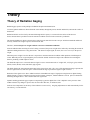
Theory
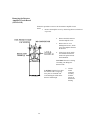
Theory of Radiation Gaging
Radiation gages operate on the principle of radiation absorption and transmission.
A beam of gamma radiation is directed from the source holder, through the process material and the belt, and onto the surface of
the detector.
Radiation which is not absorbed by the material through which it passes, is transmitted to the surface of the detector.
Process measurement is possible because the amount of radiation absorbed and transmitted is predictable.
The absorbed radiation is directly related to the weight of process material in/on the conveyor while the transmitted radiation is
inversely related to the weight of process material on the belt.
Therefore, an increased process weight results in a decrease of transmitted radiation.
Since the radiation that's not being absorbed is being transmitted, the process weight can be inferred by measuring the amount of
radiation reaching the detector at any point in time. The detector's output signal, in counts, also varies inversely to the process
weight.
When the process weight is low the detector is exposed to a maximum amount of radiation which produces a HIGH output of
counts. When the process weight is high the process material "shields" the detector and prevents radiation from reaching the
detector, producing a LOW output of counts.
The X96S Microprocessor converts the detector signal to user's measurement units of weight: lb/ft, oz/ft, kg/m, g/mt, and rate:
STon/h, Lton/h, lb/min, oz/min, MetTon/h, kg/h, kg/min.
The X96S displays the output measurement range in the selected user units. The "zero" of the measurement range represents the
lowest weight of interest, while the "span" of the measurement range represents the highest weight of interest.
Reduction of the signal "noise" due to radiation statistics is handled in the stage of signal processing known as digital filtering.
Digital filtering is a form of statistical averaging used to smooth, or dampen, random radiation as well as process-related noise.
Increasing the digital filter’s “time constant” decreases signal noise.
Dynamic tracking permits the gage response to temporarily by-pass the digital filter. This is helpful in some processes where
sudden or drastic step changes in process must be observed in their true, or unfiltered, state.
Software also compensates for the decay of the radioactive source activity. On-going adjustments are made automatically for the
rate of decay, or source half-life.

5
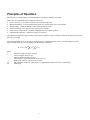
Principles of Operation
The detector's raw output signal is processed through several stages of software in the X96S.
Some of the more significant stages of signal processing are:
• Units Conversion – conversion of counts into user-selected weight units
• Measurement Range – 4-20 mA output defined by the user-selected range in user-selected units.
• Digital Filtering – signal smoothing to reduce statistical radiation noise
• Dynamic Tracking – quick gage response to quick process changes.
• Source Decay Compensation – automatic compensation for the radioisotope decay
• Calibration (Referencing) – calibration of gage to user process.
The Calibration (and Referencing) procedure relates detector output (in counts) to numeric values that accurately represent the
actual process weight.
The weight algorithm (or curve) used by the X96S software is a logrithmic function. That is, the relationship between the
detector output and the process mass denisty is mathematically expressed as:
a
uTIc
Io
LnRRc××+= )
1
()(
0
Where:
R
o= Reference weight with empty conveyor
R
c= Current weight on the conveyor
I
o= Detector signal with empty conveyor
I
c= Current detector signal with material on the conveyor
a = Width of the conveyor in units of feet (or meter)
uT = Mass absorption coefficient, which for Cs-137 approximately equals 0.04 ft2/lb or (0.008 M2/kg)
Ln = Natural Log

6
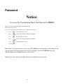
Password
Notice:
To access the Programming Menu, the Password is 101010.
Step 1: Power Up – You should now be on the Status Screen.
Step 2: Press F3 to go back.
Step 3: Now enter the password. (All digits are set at 000000 at this point.)
Press to get the digit to be # one
Press 2 times (The third digit should be highlighted.)
Press to get the digit to be # one
Press 2 times (The fifth digit should be highlighted.)
Press to get the digit to be # one
Press F4 (enter)
Note: If the wrong password was entered, press F1 (ALL0) to set all the digits to the number 0 and
you can begin re-entering the password from the beginning. Pressing F2 (RST0) will set the
individual digit that is highlighted back to the number 0.
Note: For security reasons, each digit will always be displayed as an asterisk.

7
Menus/Operation
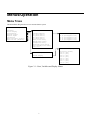
Menu Trees
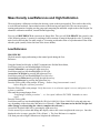
The Ronan X96S Weigh scale uses a tree structured menu system.
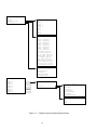
Ronan X96S – Weigh Scale
Variables Variables
Status Display
Configuration 2Variable Mapping Variable Mapping
Digital Outputs 3PV [value units]
Digital Inputs 3SV [value units] PV is [var mapped to PV]
Calibration 4TV [value units] SV is [var mapped to SV]
Reset Totalizer [OK/Abort] 5QV [value units] TV is [var mapped to TV]
Reset PD Cntr [OK/Abort] 6Rate [value units] QV is [var mapped to TV]
Weight[value units]
Speed[value units]
Head Temp [value units]
Total Weight[value units]
Filt Cnts
Status Display
Analog Bar [enable]
Displays Line 1: [var]
Line 2: [var]
Status Display Line 3: [var]
Line 4: [var]
Line 5: [var]
Line 6: [var]
Line 7: [var]
Line 8: [var]
Figure 3-1 – Root, Variables and Display Menus

8
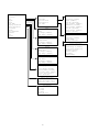
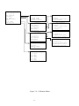
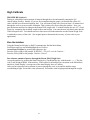
Configuration
Operation Filtering
Operation
Rate Filtering Dyn Track [enable]
Weight Detector Fault Sigma [number]
Speed Linearization Fast TC [seconds]
Head Temp Scan Time Fast Counter [number]
Display Totalizer Meduim TC [seconds]
Remote Totalizer Slow counter [number]
PD Counter Rate Slow TC [seconds]
Alarms Noise Filter [number]
Auto Reference Units Monitor [status]
Hardware Low Range [number]
Hart High Range [number] Linearization
System
Weight Linearize [enable]
Clear Table
Weight Units Config Linearize
Low Range [number]
High Range [number] Config Linearize
Speed Table Entry # [number]
Entry Used [indicator]
Speed Units Measured [value]
Low Range [number] Actual [value]
High Range [number] Set Entry
Remove Entry
Head Temp
Temp Units
Low Range [number]
High Range [number]
Display Totalizer
Total Weight [Weight]
Elpased Time [Seconds]
Totalizer Units [Units]
Ext Reset [Enable/Disabled}
Reset Totalizer
Remote Totalizer
Units per Pulse [number]
Remote Tot Units [units]
PD Counter
PD Count
PD Limit
PD Units
Reset PD Cntr

9
Continued from
Previous Page
Configuration
Operation Alarms Alarm [number]
Rate
Weight Alarm 1 Source [variable]
Speed Alarm 2 Alarm Type [none,low,high,range]
Head Temp Alarm 3 Setpoint [number]
Display Totalizer Alarm 4 Setpoint2 [number]
Remote Totalizer Alarm 5 Hysterisis [percentage]
PD Counter Alarm 6
Alarms Alarm 7 System Hardware
Auto Reference Alarm 8
Hardware CPU Card [type]
Hart Auto Reference CPU Status [status]
System DIO Card [type]
Auto Ref [Enable/Disable] DIO Status [status]
Ref Delay [milliseconds] Slot 3 Card [type]
Auto Ref Rate [number] Slot 3 Status [status]
Slot 4 Card [type]
Hardware Slot 4 Status [status]
Slot 5 Card [type]
System Hardware Slot 5 Status [status]
Source Type Slot 6 Card [type]
Speed Hardware Slot 6 Status [status]
Analog Out Cnfg Slot 7 Card [type]
Slot 7 Status [status]
Hart Slot 8 Card [type]
Slot 8 Status [status]
Tag Name [name] Display Type [type]
MultiDrop [number] Display Status [status]
Univ Rev [number] HART [type]
Spec Rev [number] HART Status [status]
System Source Type
Serial # [number] Source Type [type]
Hardware Rev [rev] Usr Def Source
Software Rev [rev] Next Reference [date]
Date [date] Next Wipe Test [date]
Hour (0-23) [hour] Next Shutter Test [date]
Minute [min]
Password Usr Def Source
Date/Time Format [sel]
Name
Half Life
Speed Hardware
Pulse
Encoder Up
Encoder Down
Line Down
Tachometer
None
Figure 3-2 – Configuration Menus

10
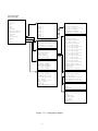
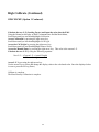
Digital Outputs
Output Output
Select Sources
Polarity Relay 1
Relay 2
Relay 3
Relay 4
TTL 1
TTL 2
TTL 3
TTL 4
Select Sources
Alarm 1 [yes/no]
Alarm 2 [yes/no]
Alarm 3 [yes/no]
Alarm 4 [yes/no]
Alarm 5 [yes/no]
Alarm 6 [yes/no]
Alarm 7 [yes/no]
Alarm 8 [yes/no]
Totalizer [yes/no]
PD Counter [yes/no]
AutoCal Ref [yes/no]
AutoCal Err [yes/no]
Ref Prompt [yes/no]
Wipe Test [yes/no]
Shutter Test [yes/no]
Empty Clamp [yes/no]
Detector Flt [yes/no]
System Alarm [yes/no]
Polarity
NO/Not Driven
NC/Driven
Open/Not Driven
Closed/Driven
Digital Inputs
Input 1 Input #
Input 2
Input 3 Use Use
Input 4 Polarity
Input 5 Not Used
Input 6 Auto Ref
Input 7 Speed Pulse
Input 8 Speed Encoder
Line Down
Totalizer Reset
Polarity
Low
High
Figure 3-3 – Digital Output and Digital Input Menus

11
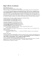
Calibration
State [state]
Ref Constants Ref Constants Low Reference
Calibrate
Cal Speed Ref Mode [mode] Reference
Ref Date [date] Ref Time [time] Ref Weight [value units]
Time MinRefCnts [counts] Ref Cap [counts]
Loop Config
Aux Loop Cfg Calibrate High Calibrate
State [state] Calibrate
Low Reference Cal Weight [value units]
High Calibrate Cal Cap [counts]
Manual Entry L.F. [L.F.]
Clear Ref/Cal
Low Reference
Cal Speed
Low Speed Cal
State [state] Low Speed [value units]
Low Reference Captured Value [counts]
High Calibrate
Manual Entry High Calibrate
Clear Ref/Cal
High Speed Cal
Loop Config High Speed [value units]
Captured Value [counts]
Loop test Pulse Factor [pulse/value]
Damping [number]
D/A trim
Aux Loop Config
SV is [var]
Aux 1 Test
Aux 1 Trim
TV is [var]
Aux 2 Test
Aux 2 Trim
Figure 3-4 – Calibration Menus

12
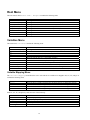
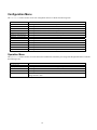
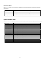
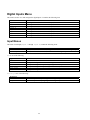
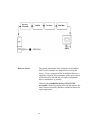
Root Menu
The root menu is titled “Ronan X96S – Weight”. It contains the following items:
ITEM FUNCTION
Variables Selecting this choice takes the user to the Variables menu
Status Displays Selecting this choice takes the user to the Status Displays menu
Configuration Selecting this choice takes the user to the Configuration menu
Digital Outputs Selecting this choice takes the user to the Digital Outputs menu
Digital Inputs Selecting this choice takes the user to the Digital Inputs menu
Calibration Selecting this choice takes the user to the Calibration menu
Reset Totalizer Selecting this choice takes the user to the Reset Totalizer menu
Reset PD Cntr Selecting this choice takes the user to the Reset PD Cntr menu
Variables Menu
The menu titled “Variables” contains the following items:
ITEM FUNCTION
Variable Mapping Selecting this choice takes the user to the Variable Mapping menu
PV Shows the current value of PV (the Primary Variable)
SV Shows the current value of SV (the Secondary Variable)
TV Shows the current value of TV (the Third Variable)
QV Shows the current value of QV (the Fourth Variable)
Rate Shows the current value of Rate (the Rate Variable)
Weight Shows the current value of Weight (the Weight Variable)
Speed Shows the current value of Speed (the Speed Variable)
Head Temp Shows the current value of Head Temp (the Head Temperature)
Total Weight Shows the current value of Total Weight (the Total Weight Variable)
Filt Cnts Shows the current value of Filter Cnts (the Filter Counts Variable)
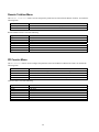
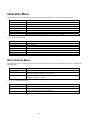
Variable Mapping Menu
The “Variable Mapping” menu allows the user to select the device variable to be mapped to PV, SV, TV, and QV. It
contains the following items:
ITEM FUNCTION
PV is Shows the device variable assigned to PV and allows the user to change the selection
SV is Shows the device variable assigned to SV and allows the user to change the selection
TV is Shows the device variable assigned to TV and allows the user to change the selection
QV is Shows the device variable assigned to QV and allows the user to change the selection
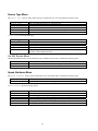
Each PV, SV, TV, and QV may each select one of the following:
SELECTION MEANING
Rate Rate (example: pounds per hour)
Weight Weight (example: pounds per linear foot)
Speed Speed (example: feet per second)
Head Temp Head Temperature (if Available)
Not Assigned Blank line

13
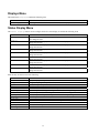
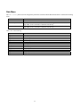
Displays Menu
The menu titled “Displays” contains the following item:
ITEM FUNCTION
Status Display Selecting this choice takes the user to the Status Display menu
Status Display Menu
The Status Display menu is used to configure the device status display. It contains the following items
ITEM FUNCTION
Analog Bar Shows the current state of the analog bar display (enabled or disabled) and allows the
user change the state.
Line 1: Shows the data to be displayed on line 1 of the status display and allows the user to
change the selection
Line 2: Shows the data to be displayed on line 2 of the status display and allows the user to
change the selection
Line 3: Shows the data to be displayed on line 3 of the status display and allows the user to
change the selection
Line 4: Shows the data to be displayed on line 4 of the status display and allows the user to
change the selection
Line 5: Shows the data to be displayed on line 5 of the status display and allows the user to
change the selection
Line 6: Shows the data to be displayed on line 6 of the status display and allows the user to
change the selection
Line 7: Shows the data to be displayed on line 7 of the status display and allows the user to
change the selection
Line 8: Shows the data to be displayed on line 8 of the status display and allows the user to
change the selection
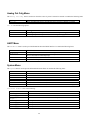
Each line may each select one of the following:
SELECTION MEANING
Rate Rate (example: pounds per hour)
Weight Weight (example: pounds per linear foot)
Speed Speed (example: feet per second)
Totalizer Totalizer (shows the accumulated weight)
PD Counter PD Counter (shows the current value in the predetermined counter)
% of Weight Shows the percent of Weight based upon the min and max Weight range
% of Rate Shows the percent of Rate based upon the min and max Rate range
% of Speed Shows the percent of Speed based upon the min and max Speed range
Head Temp Head Temperature (if Available)
4-20 mA 4-20 mA output level
Filt Cnts Filter counts (from scintillation detector) or raw analog measurement (from ionization detector)
Date & Time Current date and time
Tot Elspd Time Shows the Total Elsped Time since the last time Totalizer was reset
Not Assigned Blank line

14
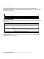
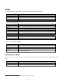
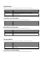
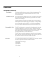
Configuration Menu
The Variables menu is used to access area configuration menus. It contains the following items:
ITEM FUNCTION
Operation Selecting this choice takes the user to the Operation menu
Rate Selecting this choice takes the user to the Rate menu
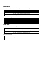
Weight Selecting this choice takes the user to the Weight menu
Speed Selecting this choice takes the user to the Speed menu
Head Temp Config Selecting this choice takes the user to the Head Temp menu
Display Totalizer Selecting this choice takes the user to the Display Totalizer menu
Remote Totalizer Selecting this choice takes the user to the Remote Totalizer menu
PD Counter Selecting this choice takes the user to the PD Counter menu
Alarms Selecting this choice takes the user to the Alarm menu
Auto Reference Selecting this choice takes the user to the Auto Reference menu
Hardware Selecting this choice takes the user to the Hardware menu
HART Selecting this choice takes the user to the HART menu
System Selecting this choice takes the user to the System menu
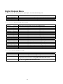
Operation Menu
The Operation menu is used to access the menus and variables that control the processing of the Weight Scale data. It contains
the following items:
ITEM FUNCTION
Filtering Selecting this choice takes the user to the Filtering menu
Empty Clamp Selecting this choice takes the user to the Empty Clamp menu
Detector Fault Selecting this choice takes the user to the Detector Fault menu
Linearization Selecting this choice takes the user to the Linearization menu
Scan Time Shows the amount of time to accumulate each weight sample and allows the user to
change the time value.

15
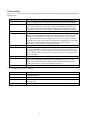
Filtering Menu
The Filtering menu is used to configure the parameters associated with the weight measurement filter. It contains the
following items:
ITEM FUNCTION
Dyn Track Shows the current state of the dynamic tracking filter (enabled or disabled) and allows
the user to change the state. If disabled the filter uses only the Slow Time Constant.
Sigma Shows the (sigma) multiplier used to determine maximum number of raw counts
variation (for scintillation) or raw analog value (for ion chamber) that the input can
vary from the current filtered counts before changing to the dynamic filter. Sigma is
the square root of the current filtered counts. Also allows user to change this number.
Fast TC Fast Time Constant value to be used when the Fast Counter reaches zero.
Fast Counter Shows the fast count down counter value. If gauge has been in dynamic tracking long
enough to be using Medium filter and the raw counts continued to exceed the sigma
value, the fast counter value is decreased each consecutive scan. The Fast counter
value resets and returns back to the original value if the raw counts do not continue to
exceed the sigma value. Once the Fast TC is triggered, it will continue to be used until
the counts are within the sigma value for the Fast counter number of times
consecutively. Also allows user to change this number.
Medium TC Medium Time Constant value to be used when the Slow Counter reaches zero.
Slow Counter Shows the slow count down counter value. If gauge is in dynamic tracking, and the
raw counts continued to exceed the sigma value, the slow counter value is decreased
each consecutive scan. The Slow counter value resets and returns back to the original
value if the raw counts do not continue to exceed the sigma value. Also allows user to
change this number.
Slow TC Slow Time Constant value to be used if the the Slow Counter has not reached zero.
Noise Filter Shows the maximum number of potentially erroneous measurements in a row to
bridge before deciding that a step change has occurred in the weight value. Also it
allows user to change this number. Erroneous measurement is define when the raw
signal is 4 times the pre-selected sigma multiplier by the user.
Monitor Shows the current state of the filtering mechanism.
Monitor (filter state) one of the following:
Monitor MEANING
ERROR Filter is not initialized (this state should not occur during normal operation of the
X96S Weigh Scale)
FILL The slow filter buffer is filling.
TRACK The (slow or medium or fast filter buffer is filled and the filter is tracking changes in
the weight value
REFILL A step change has occurred and the walking average buffer is refilling.

16
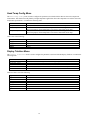
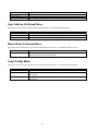
Linearization Menu
The X96S is capable of performing a multi-point linearization of the weight data when required by an application. The
linearization table contains thirty entries, numbered 1 through 30. Each entry consists of a measured value, an actual value, and a
flag that indicates if the entry is used2.
The Linearization menu is used to control the linearization mechanism. It contains the following items:
ITEM FUNCTION
Linearize Shows the current state of the Linearization mechanism (enabled or disabled) and
allows the user to change the state.
Clear Table This item invokes a method that clears all entries in the linearization table
Config Linearize Selecting this item takes the user to the Config Linearize menu
Config Linearize Menu
The Config Linearize menu is used to configure the parameters associated with linearization of the measured data. It contains
the following items:
ITEM FUNCTION
Table Entry # Shows, and allows the user to select, an entry in the linearization table
Entry Used Shows if the entry is used or not.
Measured Shows, and allows the user to set, the measured value associated with this linearization
table entry. This is the nonlinear value calculated by the X96S when linearization is
disabled.
Actual Shows, and allows the user to set, the actual value associated with this linearization
table entry. This value is the result of actual level knowledge, and compares to the
Measured value above.
Set Entry This item invokes a method that sets a table entry
Remove Entry This item invokes a method that removes a table entry
Scan Time Menu
The Scan Time menu is used to configure the rate the input board scans the detector signal and the rate the microprocessor
updates the LCD display and the output signal.
2 Not all of the entries need to be used and the entries do not need to be used in any particular order.
Page is loading ...
Page is loading ...
Page is loading ...
Page is loading ...
Page is loading ...
Page is loading ...
Page is loading ...
Page is loading ...
Page is loading ...
Page is loading ...
Page is loading ...
Page is loading ...
Page is loading ...
Page is loading ...
Page is loading ...
Page is loading ...
Page is loading ...
Page is loading ...
Page is loading ...
Page is loading ...
Page is loading ...
Page is loading ...
Page is loading ...
Page is loading ...
Page is loading ...
Page is loading ...
Page is loading ...
Page is loading ...
Page is loading ...
Page is loading ...
Page is loading ...
Page is loading ...
Page is loading ...
Page is loading ...
Page is loading ...
Page is loading ...
Page is loading ...
Page is loading ...
Page is loading ...
Page is loading ...
Page is loading ...
Page is loading ...
Page is loading ...
Page is loading ...
Page is loading ...
Page is loading ...
Page is loading ...
Page is loading ...
-
 1
1
-
 2
2
-
 3
3
-
 4
4
-
 5
5
-
 6
6
-
 7
7
-
 8
8
-
 9
9
-
 10
10
-
 11
11
-
 12
12
-
 13
13
-
 14
14
-
 15
15
-
 16
16
-
 17
17
-
 18
18
-
 19
19
-
 20
20
-
 21
21
-
 22
22
-
 23
23
-
 24
24
-
 25
25
-
 26
26
-
 27
27
-
 28
28
-
 29
29
-
 30
30
-
 31
31
-
 32
32
-
 33
33
-
 34
34
-
 35
35
-
 36
36
-
 37
37
-
 38
38
-
 39
39
-
 40
40
-
 41
41
-
 42
42
-
 43
43
-
 44
44
-
 45
45
-
 46
46
-
 47
47
-
 48
48
-
 49
49
-
 50
50
-
 51
51
-
 52
52
-
 53
53
-
 54
54
-
 55
55
-
 56
56
-
 57
57
-
 58
58
-
 59
59
-
 60
60
-
 61
61
-
 62
62
-
 63
63
-
 64
64
-
 65
65
-
 66
66
-
 67
67
-
 68
68


Ronan Engineering X96S Instructions And Operating Manual
- Category
- Measuring, testing & control
- Type
- Instructions And Operating Manual
Ask a question and I''ll find the answer in the document
Finding information in a document is now easier with AI
Related papers
Other documents
-
Optex SS Checker SC-T4 User manual
-
Spirax Sarco VLM20 In-line Vortex Flowmeter and VIM20 Vortex Insertion Flowmeter Installation And Maintenance Instructions
-
Sierra 240S/241S Series User manual
-
-
-
Rosemount 8750W Transmitter Owner's manual
-
-
-
-