Maytag iQ Zone Zoning System Installation guide

Type
Installation guide
iQ ZONE
TM
SYSTEM
SAFETY AND WARNING NOTES
Before operation, ensure you have read and understood all the information and instructions in this leaflet.
For more detail, refer to the iQ Zone Technical Data Sheet.
ATTENTION: Disconnect the system from the power supply before undertaking any installation,
maintenance, modification or removal.
As a minimum, the following conditions must be met before operation:
All wires must be properly secured in terminal blocks.
Unit and power supply cables must be properly fused.
All output lines must be correctly rated and connected with the correct polarity.
No modification should be made while the unit is in operation.
Do not introduce any object into the unit.
Keep away from fire and water.
COMPONENTS
The Zoning System is composed of four types of electronic components and a number of mechanical
components including dampers and a bypass, depending on the installation.
The electronic components are:
1) Airzone Controller (1 per installation)
2) Zone Modules (1 per damper)
3) Touch Zone Thermostats (1 per zone)
4) Power Supply (1 per installation)
Optionally, the system may be fitted with remote temperature sensors.
ZONING SYSTEM OPERATION
Some important characteristics of the iQ Zoning System are:
1) It operates with 12 VDC.
2) It requires a single 4 conductor, stranded and shielded cable to all system elements.
3) The dampers are power open/power close.
4) The way the Airzone Controller communicates with the Zone Modules, is based on
a proprietary communication protocol.
5) It communicates with the iQ Controller with only two data wires.
WIRING INFORMATION
The zoning system wiring is very simple, but great care must be taken during its layout and connection.
All wiring must be made with stranded shielded communication cable, AWG20, Belden type 6402FE,
CAT5e, or equivalent. The cable should NOT be stapled in place. If it is required to have the cable fixed to
any part of the building structure, clamps with cable protection should be used. DO NOT crush or kink the
cable.
IMPORTANT: Failure to follow these recommendations may result in an unreliable installation that
will seriously affect the operation of the iQ Zoning system.
See the typical wiring layout and Daisy chain connection below:
Connection Diagram Connections detail
AIRZONE CONTROLLER
Description Description
1
Set configuration
push button
9 Fire Alarm Contact
2 Not used 10 Not used
3 Bypass Connector 11 iQ bus connection
4 12VDC Input 12
Local zoning system
bus Connection
5 J2 Jumper 13 Not used
6
Supply Temperature
Probe input
14 Not used
7 Not used 15
Switches for system
configuration
8 Not used
Inbound
Bus
Thermostat
Cable
Outbound
Bus
1
3
4
2
5
13 12
7 9
6
8
11 10 14
15
ZONE MODULE
THERMOSTAT DESCRIPTION
The Touch Thermostat is the user interface for the installer to configure the Zone Module, and also for the
user to change the temperature settings for the zone and configure time scheduled setpoints.
Description
1 Days of the week
2 Hour display (24 hr)
3 Automatic Mode
4 Manual Mode
5 Zone ON/OFF icon
6 Temperature display
7 Temperature units
8 Selection arrows
9 System Mode
POWER SUPPLY
The universal auto detection AC power supply has been designed to provide the necessary current and
voltage to the Airzone zoning system.
ASSEMBLY INSTRUCTIONS
AIRZONE CONTROLLER
This unit must be assembled on a standard DIN rail– 35mm x
75mm.
Place the upper part of the controller (with the power supply on the
upper left) on the upper edge of the rail. Using a screwdriver,
gently pull downward on the release tab (at the center of the lower
edge), and snap it onto the rail. To disassemble, gently pull
downward on the release tab until the controller can be lifted from
the DIN rail.
ZONE MODULE
The Zone Module is normally installed mounted to the Damper Motor,
as shown in the figure on the right. In this case it should be assembled
onto the guides located on the motorized damper motor frame.
Disconnect all the connectors, fit the local-module box on the rail in the
motor case, and slide until fully seated.
Alternatively, the module may be located remote from the damper motor
for convenience or in order to comply with bus wire length limitations.
THERMOSTAT
The thermostat consists of three parts: base, cover, and touch
screen. Follow these steps for correct installation:
1) Attach the base to the wall with two screws, passing the
communication-bus wires through the circular hole provided.
2) Separate the cover from the touch screen, using the slot
provided in the bottom of the cover (use a coin to do this
rather than a sharp object).
3) Pass the communication bus wires through the hole in the
cover. Mount the cover onto the two top hinges, and snap the
tabs of the base into the cover.
4) Connect the communication bus wires to the terminals on the
cover (see electrical diagram). Insert them under the metal
tabs and screw firmly in place.
5) Mount the top of the touch screen onto the hinges on the
cover. Pull gently down and back until the two parts are
joined.
POWER SUPPLY
Ventilation holes must be kept clear for a minimum clearance of 1 inch (25 mm) on all sides. To mount, tilt
the top of the unit backwards and clip the top edge of the lock onto the metal rail. Tilt the bottom of the
unit backwards and click into place.
Ensure that the cables used are suitable for the load, see technical data below. Ensure that cables are
correctly stripped and connected. Ensure correct polarity at the output terminals (red +, black -).
The internal fuse protects the unit and is not user-replaceable. In the event of an internal failure, the unit
must be replaced.
Description
1 Motor Control Output
2 Remote Temperature Sensor Input
3 Zoning Bus Connector
4 Thermostat Connector
5 Occupancy Detector Input
6 Door/Window Contact Input
Description
1 Power supply 12 Vdc
2 Error indication LED (red)
3 Operation LED (green)
4 Power supply 110 to 240Vac
3
4
5
6
2 1
1
2
3
4
9
1
2
3
4
5
6
7 8
PLANNING THE INSTALLATION
Before beginning the physical installation, it is essential that the installer plan out the entire zoning
system. This includes deciding (along with the homeowner) the following:
the total number of zones to be set up
which spaces and which ducts are to be included in each zone
the zone number (1 - 8) for each zone location
the location for each zone thermostat
the location for each damper in the ductwork system
the module number to be assigned to each damper (1 - 8 for master modules which will be
connected to zone thermostats, 9 - 32 for subordinate modules)
the routing path of the communication cable that will interconnect the components (for
troubleshooting purposes)
At the end of this document a Module/Damper Location Sheet, Zone Identification Sheet, and Zone and
Module Identification Sheet are provided to aid in the planning process.
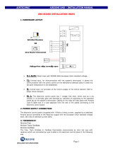
CONNECTION
These are the recommended installation steps.
1) Have a layout drawing of the house and locate where each thermostat and each damper will be
installed. Define the address each module will be assigned and the path the communications wire
will follow . Keep that document in your records for future maintenance. Forms are included at the
end of this document.
2) Install all dampers according to your design and where the customer wants to have controlled
airflow. Be sure that the dampers are in good condition (not deformed). Install the dampers
according with the local building recommendations. Be sure that these two conditions are followed:
a) Mount the damper in such way that the motor is accessible
b) Be sure that the damper will be accessible for service.
3) If a bypass is required for this installation, install it now.
4) Lay out the communication cable and attach the cables to the connectors as indicated in the Training
Manual.
5) Install the Airzone Controller and the 12VDC power supply on their DIN rails, near the air handler
unit or furnace.
6) Wire the power supply, connect power on the Airzone Controller, and verify that the power LED is
ON
7) Disconnect the DC power from the Airzone controller.
8) Connect all the modules to the communication bus, thermostat sub bases and damper motor cables,
but do not install the thermostat touch screens.
9) Power on the Airzone Controller.
10) Verify that there is 3 VDC between the contacts + and – of the thermostat bases.
11) Install the thermostat touch screens into their bases
12) Proceed with the initial configuration for all master modules connected to the thermostats.
13) Using a separate Installation thermostat, proceed with the initial configuration of all subordinate zone
modules.
14) Configure any additional module parameters if required (remote temperature sensor, door contact,
motion contact, etc.)
15) Save the configuration in the Airzone Controller. (IMPORTANT:, follow the procedure explained in
the Training Manual).
16) Cycle the power OFF then ON in the Airzone Controller.
17) All dampers should be open.
18) Install the J2 jumper in the Airzone controller
19) Install the supply air temperature probe and connect to input 6 of the Airzone Controller.
(IMPORTANT: Do not proceed until this step is completed)
20) Proceed to install the iQ thermostat as indicated in its manual.
21) Connect the iQ communication bus in the Air handler/Furnace unit to the Airzone Controller (please,
see both Training Manuals)
22) Verify that the iQ thermostat shows under the current mode, “Zone Control”.
Error
Description Corrective action
Err 1
Damper blocked
Check that the zone control’s connection to the motorized system
has not shorted out.
Check that the motorized system is not blocked.
Err 2
No zone control sensor
Check that the circuit of the sensor connected to the zone control (if
any) is not open. Check the configuration of theZcPcparameter.
Err 3
Zone-control sensor
short-circuit
Check that the circuit of the sensor connected to the zone control (if
any) has not shorted out. Check the configuration of theZcPc
parameter
Err 4
Local communication
error
Check the connections and wiring between the zone control and the
thermostat
Err 5
Bus communications
error
Check the zone control’s connection to the bus.
Err 6
Damper not connected
Check the zone control’s connection to the motorized system. Check
that the motorized system is not free.
CONFIGURATION
The Zone Module has a number of parameters that have to be configured. As indicated before, the Zone
Module requires the use of a Zone Thermostat to proceed with its configuration.
This is a list of the parameters, its description and ranges of selection.
Parameter Description Value
ZCOn
Zone Module Role
MAS : Master
Sub : Subordinate
ZCid
Zone Module ID Number (the
address of the zone module)
If Master : 1 to 8 (this defines the zone
number)
If Subordinate : 9 to 32
perC
Zone weight Percentage 10% to 100%
tCiD
(for subordinate modules only)
Zone Number
Must match one of the zone numbers assigned
to a master module (1 - 8)
zCpC
Zone Module Probe Configuration
Off : default value
rpt : measurement by a remote temperature
sensor
ZCSI
Zone Module Sleep Input (motion
detector)
Off : default value
NO : activates when closing the circuit
nC : activates when opening the circuit
ZCrI
Zone Module Remote Input (door
or window contact)
Off : default value
NO : activates when closing the circuit
nC : activates when opening the circuit
Sbdt
Stand By Display Temperature
At : ambient temperature
St : set point temperature
OFSt
Offset (adjust the zone temperature
reading)
-5ºF to +5ºF (-3 to +3°C)
zCfV
Zone Module Firmware Version Current firmware version (Read Only)
ZtfV
Zone Thermostat Firmware Version Current firmware version (Read Only)
SCfV
System Controller Firmware
Version (Airzone Controller)
Current firmware version (Read Only)
AIRZONE CONTROLLER
Power Supply Voltage
12Vdc ± 10%
SUPPLY
Current Supply I
max
= 1A
Communication Wires 2 Wires
Supply Wires 2 Wires
PORT OF THE LOCAL
COMMUNICATION BUS
Bus Voltage Supply 12Vdc – 10%
Input Type Free Voltage
ALARM BRIDGE
Maximum Resistance 2K
Input Type Free Voltage
REMOTE ON/OFF
Maximum Resistance 2K
TEMPERATURE PROBE
Analogue Inputs NTC Airzone
PHYSICAL FEATURES
Dimensions (W x L x H)
in(mm)
2.87(73) x 6.2(157.5) x 3.54(90)
THERMOSTAT
Power supply voltage
3,3Vdc ± 10%
POWER SUPPLY AND
CONSUMPTION
Stand By power consumption 108 mW
In storage °F(°C) -4 to 158 (-20 to 70)
In operation °F(°C) 23 to 95 (-5 to 35)
Reading precision °F(°C) 0.2 (0.1)
OPERATING
TEMPERATURES
Display precision °F(°C) 1.0 (0.5)
Communications 2 wires (W , Y)
Power supply 2 wires (+ , -)
Distance from the zone controller
ft(m)
14 (4.26)
Cable Cut in(mm) 0.25 (6)
CONECTION
Lineal Resistor 8 /km
PHYSICAL FEATURES
Dimensions W
1
x W
2
x L x H in(mm)
0.82(20.9) x 1.08(27.4) x
4.12(104.9) x 3.59(91.2)
ZONE MODULE
Power Supply Voltage
12Vdc ± 10%
Max. Power Current Imax = 300mA
Power Current on StandBy Isb = 7 mA
Communication wires 2 wires
LOCAL BUS COMMUNICATIONS
PORT
Power wires 2 wires
Power supply
3,3Vdc ± 10%
THERMOSTAT
COMMUNICATIONS PORT
Current 10 mA
ANALOGUE INPUTS
Temperature Probe Input NTC Airzone
Power Voltage
± 12 Vdc
Voltage at rest 0 Vdc
MOTOR POWER SUPPLY
Maximum Current Input 280 mA
PHYSICAL FEATURES
Dimensions (W x L x H) in(mm)
0.67(17) x 2.32(59) x
1.75(4.5)
POWER SUPPLY
Rated input voltage 100 Vac ~ 240 Vac
AC Voltage Range 90 Vac ~ 264 Vac
DC Voltage Range 120 – 375 Vdc
Frequency 47 – 63 Hz
INPUT
Rated Input Current (max) Imax = 300 mA
Ripple < 50 Vp-p
Output short circuit Hiccup Mode
OUTPUT
Hold-up Time (230 Vac) > 30 ms
Temperature (Storage) °F(°C) -13 to 185 (-25 to 85)
Temperature (Operation) °F(°C) -13 to 160 (-25 to 71)
OPERATING TEMPERATURES
Humidity 20% ~ 95% RH
PHYSICAL FEATURES
Dimensions H x W x D in(mm)
3.58(91) x 0.71(18) x
2.21(56.2)
AIRZONE CONTROLLER
L
H
POWER SUPPLY
L
W
H
L
H
W
ZONE MODULE
L
H
W
THERMOSTAT
Zone and Module Identification Sheet
Zone 1
Zone 2
Zone 3
Zone 4
Zone 5
Zone 6
Zone 7
Zone 8
Master Module
(1-8)
Zone Weight %
= 100%
Zone Identification
Zone Room(s)
Thermostat
Location
Notes
Module/ Damper Location Sheet
Specifications and illustrations subject to change without
notice and without incurring obligations.
Printed in U.S.A (07/12)
665D-0712
iQ Zone
TM
is a trademark of Nortek Global HVAC, LLC.
© Nortek Global HVAC, LLC 2015. All Rights Reserved.
  • Page 1 1
  • Page 2 2
  • Page 3 3
  • Page 4 4
  • Page 5 5
  • Page 6 6

Maytag iQ Zone Zoning System Installation guide

Type
Installation guide

Ask a question and I''ll find the answer in the document

Finding information in a document is now easier with AI