Page is loading ...

IMS5400-DS
IMS5600-DS
IMS5400-TH
Operating Instructions
interferoMETER

MICRO-EPSILON
MESSTECHNIK
GmbH & Co. KG
Koenigbacher Str. 15
94496 Ortenburg / Germany
Tel. +49 (0) 8542 / 168-0
Fax +49 (0) 8542 / 168-90
e-mail [email protected]
www.micro-epsilon.com

IMS5x00
Contents
1. Safety ........................................................................................................................................ 7
1.1 Symbols Used ................................................................................................................................................. 7
1.2 Warnings .......................................................................................................................................................... 7
1.3 Notes on CE Marking ...................................................................................................................................... 7
1.4 Intended Use ................................................................................................................................................... 8
1.5 Proper Environment ......................................................................................................................................... 8
2. Laser Class ............................................................................................................................... 9
3. Functional Principle, Technical Data ..................................................................................... 10
3.1 Short Description ........................................................................................................................................... 10
3.2 Measuring Principle ....................................................................................................................................... 10
3.3 Term Definitions ............................................................................................................................................. 11
3.4 Operating Modes ........................................................................................................................................... 11
3.5 Sensors .......................................................................................................................................................... 11
3.6 Technical Data .............................................................................................................................................. 12
4. Delivery .................................................................................................................................. 15
4.1 Unpacking/Included in Delivery .................................................................................................................... 15
4.2 Storage .......................................................................................................................................................... 15
5. Installation .............................................................................................................................. 16
5.1 IMC5x00 Controller ........................................................................................................................................ 16
5.2 Controller Operating Elements ...................................................................................................................... 17
5.3 LEDs Controller .............................................................................................................................................. 18
5.4 Electrical Connections Controller .................................................................................................................. 19
5.4.1 Handling of Pluggable Screw Terminals ...................................................................................... 19
5.4.2 Grounding, Shielding ................................................................................................................... 19
5.4.3 Supply Voltage (Power) ................................................................................................................ 19
5.4.4 RS422 ........................................................................................................................................... 19
5.4.5 Ethernet, EtherCAT ....................................................................................................................... 20
5.4.6 Analog Output .............................................................................................................................. 20
5.4.7 Switching Outputs (Digital I/O) ..................................................................................................... 21
5.4.8 Synchronization (Inputs/Outputs) ................................................................................................ 22
5.4.9 Triggering ...................................................................................................................................... 23
5.4.10 Encoder Inputs ............................................................................................................................. 24
5.5 Sensor Cable ................................................................................................................................................. 24
5.6 Sensors .......................................................................................................................................................... 26
5.6.1 Sensor Dimensions ...................................................................................................................... 26
5.6.2 Start of Measuring Range............................................................................................................. 26
5.6.3 Mounting, Mounting Adapter ....................................................................................................... 26
6. Operation ................................................................................................................................ 27
6.1 Initial Operation .............................................................................................................................................. 27
6.2 Control via Ethernet ....................................................................................................................................... 27
6.2.1 Requirements ............................................................................................................................... 27
6.2.2 Access via Web Interface ............................................................................................................. 28
6.3 Select a Sensor .............................................................................................................................................. 29
6.4 Button Multifunction ....................................................................................................................................... 29
6.5 Positioning the Target, Distance Measurement ............................................................................................. 30
6.6 Positioning the Target, Thickness Measurement .......................................................................................... 31
6.7 Measurement Configuration .......................................................................................................................... 31
6.8 FFT Signal ...................................................................................................................................................... 32
6.9 Distance and Thickness Measurement with Web Page Display ................................................................... 33
6.10 Load / Save Settings ...................................................................................................................................... 35
7. Advanced Settings ................................................................................................................. 36
7.1 Inputs ............................................................................................................................................................. 36
7.1.1 Synchronization ............................................................................................................................ 36
7.1.2 Encoder ........................................................................................................................................ 36
7.1.3 Key Function ................................................................................................................................. 36
7.1.4 Input Level .................................................................................................................................... 36
7.1.5 Termination ................................................................................................................................... 36
7.2 Data Recording .............................................................................................................................................. 37
7.2.1 Measuring Rate ............................................................................................................................ 37
7.2.2 Masking the Evaluation Range..................................................................................................... 38
7.2.3 Exposure Mode ............................................................................................................................ 38
7.2.4 Detection Threshold ..................................................................................................................... 39
7.2.5 Material Selection Thickness Measurement ................................................................................ 40
7.2.6 Input Triggering ............................................................................................................................ 41
7.2.6.1 General ...................................................................................................................... 41
7.2.6.2 Triggering Data Recording ....................................................................................... 42
7.2.6.3 Triggering Data Output ............................................................................................. 42
7.2.6.4 Trigger Time Difference ............................................................................................. 42
7.3 Signal Processing, Calculation ...................................................................................................................... 43
7.3.1 Data Source, Parameter, Programs ............................................................................................. 43
7.3.2 Definitions ..................................................................................................................................... 44
7.3.3 Measurement Averaging .............................................................................................................. 45
7.3.3.1 Moving average ........................................................................................................ 45
7.3.3.2 Recursive average .................................................................................................... 46
7.3.3.3 Median ...................................................................................................................... 47

IMS5x00
7.4 Postprocessing .............................................................................................................................................. 48
7.4.1 Zeroing, Mastering ....................................................................................................................... 48
7.4.2 Statistics ....................................................................................................................................... 49
7.4.3 Data Reduction, Output Data Rate ............................................................................................... 50
7.4.4 Error Handling (Hold Last Value) ................................................................................................. 50
7.5 Outputs .......................................................................................................................................................... 51
7.5.1 General ......................................................................................................................................... 51
7.5.2 RS422 ........................................................................................................................................... 51
7.5.3 Data Output Ethernet.................................................................................................................... 51
7.5.4 Analog Output .............................................................................................................................. 52
7.5.4.1 Calculation of the Measurement Value at the Current Output ................................. 53
7.5.4.2 Calculation of the Measurement Value at the Voltage Output ................................. 53
7.5.4.3 Characteristics Distance Value and Analog Output ................................................. 54
7.5.5 Digital Outputs, Limit Value Monitoring ........................................................................................ 55
7.5.6 Data Output, Interface Selection .................................................................................................. 55
7.5.7 Ethernet Settings .......................................................................................................................... 56
7.6 System settings ............................................................................................................................................. 57
7.6.1 Unit Website.................................................................................................................................. 57
7.6.2 Language Support........................................................................................................................ 57
7.6.3 Key Lock ....................................................................................................................................... 57
7.6.4 Load and Safe .............................................................................................................................. 57
7.6.5 Import, Export ............................................................................................................................... 58
7.6.6 Access Authorization .................................................................................................................... 59
7.6.7 Reset Controller ............................................................................................................................ 60
7.6.8 Light Source ................................................................................................................................. 60
7.6.9 Material Table ................................................................................................................................ 60
7.6.10 Switching between Ethernet and EtherCAT ................................................................................. 60
8. Thickness Measurement ........................................................................................................ 61
8.1 Requirements ................................................................................................................................................. 61
8.2 Sensor Selection ............................................................................................................................................ 61
8.3 Material Selection .......................................................................................................................................... 61
8.4 FFT Signal ...................................................................................................................................................... 62
8.4.1 Measurement Chart ...................................................................................................................... 62
9. Liability for Material Defects .................................................................................................. 63
10. Service, Repair ...................................................................................................................... 63
11. Decommissioning, Disposal .................................................................................................. 63
Appendix ................................................................................................................................. 64
A 1 Accessories, Services ............................................................................................................ 64
A 2 Factory Settings ..................................................................................................................... 64
A 3 ASCII Communication with Controller .................................................................................. 65
A 3.1 General .......................................................................................................................................................... 65
A 3.2 Commands Overview .................................................................................................................................... 65
A 3.3 General Commands ...................................................................................................................................... 68
A 3.3.1 General ......................................................................................................................................... 68
A 3.3.1.1 Help ........................................................................................................................... 68
A 3.3.1.2 Controller Information ............................................................................................... 68
A 3.3.1.3 Reply type ................................................................................................................. 68
A 3.3.1.4 Paramter Overview .................................................................................................... 68
A 3.3.1.5 Synchronization ....................................................................................................... 69
A 3.3.1.6 Termination Resistor at Sync/Trig Input .................................................................... 69
A 3.3.1.7 Booting the Sensor .................................................................................................. 69
A 3.3.1.8 Reset Counter ........................................................................................................... 69
A 3.3.2 User Level ..................................................................................................................................... 70
A 3.3.2.1 Changing the User Level ......................................................................................... 70
A 3.3.2.2 Changing to User Level ............................................................................................ 70
A 3.3.2.3 Querying the User Level .......................................................................................... 70
A 3.3.2.4 Defining a Standard User ......................................................................................... 70
A 3.3.2.5 Changing the Password .......................................................................................... 70
A 3.3.3 Sensor .......................................................................................................................................... 71
A 3.3.3.1 Info about Calibration Tables .................................................................................... 71
A 3.3.3.2 Sensor Number ......................................................................................................... 71
A 3.3.3.3 Sensor Information ................................................................................................... 71
A 3.3.3.4 Pilot Laser ................................................................................................................. 71
A 3.3.3.5 SLED ......................................................................................................................... 71
A 3.3.4 Triggering ...................................................................................................................................... 72
A 3.3.4.1 Select Trigger Source ............................................................................................... 72
A 3.3.4.2 Output of Triggered Values, With/Without Averaging .............................................. 72
A 3.3.4.3 Trigger Type .............................................................................................................. 72
A 3.3.4.4 Active Level Trigger Input ......................................................................................... 72
A 3.3.4.5 Software Trigger Pulse .............................................................................................. 72
A 3.3.4.6 Number of Output Measurement Values .................................................................. 72
A 3.3.4.7 Trigger Level TrigIn .................................................................................................... 72
A 3.3.4.8 Maximum Encoder Triggering .................................................................................. 73
A 3.3.4.9 Minimum Encoder Triggering ................................................................................... 73
A 3.3.4.10 Step Size Encoder Triggering ................................................................................... 73
A 3.3.4.11 Example .................................................................................................................... 73

IMS5x00
A 3.3.5 Encoder ........................................................................................................................................ 74
A 3.3.5.1 Encoder Interpolation Depth .................................................................................... 74
A 3.3.5.2 Effect of the Reference Track .................................................................................... 74
A 3.3.5.3 Encoder Value ........................................................................................................... 74
A 3.3.5.4 Setting Encoder Value per Software ......................................................................... 74
A 3.3.5.5 Reset the Detection of the First Marker Position ...................................................... 74
A 3.3.5.6 Maximimum Encoder Value ...................................................................................... 74
A 3.3.5.7 Encoder3 On/Off ....................................................................................................... 74
A 3.3.6 Interfaces ...................................................................................................................................... 75
A 3.3.6.1 Ethernet IP Settings .................................................................................................. 75
A 3.3.6.2 Setting for Ethernet Transmission of Measured Values ........................................... 75
A 3.3.6.3 Setting the RS422 Baud Rate ................................................................................... 75
A 3.3.6.4 Change Ethernet / EtherCAT .................................................................................... 75
A 3.3.6.5 Measurements per frame .......................................................................................... 75
A 3.3.6.6 TCP On/Off ................................................................................................................ 75
A 3.3.7 Parameter Management, Load / Save Settings ........................................................................... 76
A 3.3.7.1 Safe / Load Connection Settings .............................................................................. 76
A 3.3.7.2 Show Changed Parameters ..................................................................................... 76
A 3.3.7.3 Export of Parameter Sets to PC ............................................................................... 76
A 3.3.7.4 Import of Parameter Sets from PC ........................................................................... 76
A 3.3.7.5 Default Settings ......................................................................................................... 76
A 3.3.7.6 Editing, Storing, Displaying, Deleting Measurement Settings ................................. 77
A 3.3.8 Measurement ................................................................................................................................ 78
A 3.3.8.1 Measuring Rate ......................................................................................................... 78
A 3.3.8.2 Masking the Evaluation Ranges ............................................................................... 78
A 3.3.8.3 Peak Detection Threshold ........................................................................................ 78
A 3.3.9 Material Data Base ...................................................................................................................... 79
A 3.3.9.1 Material Table ............................................................................................................ 79
A 3.3.9.2 Select Material........................................................................................................... 79
A 3.3.9.3 Display Material Properties ....................................................................................... 79
A 3.3.9.4 Edit Material Table ..................................................................................................... 79
A 3.3.9.5 Delete a Material ....................................................................................................... 79
A 3.3.10 Measurement Value Processing................................................................................................... 80
A 3.3.10.1 List of Possible Displacement and Thickness Signals for Statistical Calculation ... 80
A 3.3.10.2 Generate Statistic Signals ......................................................................................... 80
A 3.3.10.3 List of Statistical Signals ........................................................................................... 80
A 3.3.10.4 Reset Statistical Calculation ..................................................................................... 80
A 3.3.10.5 Statistics Eample ...................................................................................................... 81
A 3.3.10.6 List of Signals which can be Parameterized ............................................................. 82
A 3.3.10.7 Master Signal Parameterization ................................................................................ 82
A 3.3.10.8 List of Possible Signals for Mastering ....................................................................... 82
A 3.3.10.9 Masters / Zero ........................................................................................................... 82
A 3.3.10.10 Mastering Example ................................................................................................... 82
A 3.3.10.11 Channel Computation ............................................................................................... 84
A 3.3.10.12 List of possible calculation signals ........................................................................... 84
A 3.3.11 Data Output .................................................................................................................................. 85
A 3.3.11.1 Selection of Digital Output ........................................................................................ 85
A 3.3.11.2 Data Output Rate ...................................................................................................... 85
A 3.3.11.3 Reduction Counter of Measurement Value Output .................................................. 85
A 3.3.11.4 Error Processing ....................................................................................................... 85
A 3.3.12 Select Measurement Values to be Output ................................................................................... 86
A 3.3.12.1 General ...................................................................................................................... 86
A 3.3.12.2 Data Selection of Ethernet ........................................................................................ 86
A 3.3.12.3 List of Possible Ethernet Signals .............................................................................. 86
A 3.3.12.4 List of Selected Signals, Transfer Sequence via Ethernet ........................................ 86
A 3.3.13 Switching Outputs ........................................................................................................................ 87
A 3.3.13.1 Error Switching Outputs ........................................................................................... 87
A 3.3.13.2 Setting the Signal to be Evaluated ........................................................................... 87
A 3.3.13.3 List of Possible Signals for Error Output .................................................................. 87
A 3.3.13.4 Setting Limit Values................................................................................................... 87
A 3.3.13.5 Setting Value ............................................................................................................. 87
A 3.3.13.6 Switching Behavior for Error Outputs ....................................................................... 87
A 3.3.14 Analog Output .............................................................................................................................. 88
A 3.3.14.1 Data Selection ........................................................................................................... 88
A 3.3.14.2 List of Possible Signals for Analog Output ............................................................... 88
A 3.3.14.3 Output Range ............................................................................................................ 88
A 3.3.14.4 Setting the Scaling of DAC ....................................................................................... 88
A 3.3.14.5 Setting the Scaling Range ........................................................................................ 88
A 3.3.15 Key Functions ............................................................................................................................... 89
A 3.3.15.1 Multifunction Button .................................................................................................. 89
A 3.3.15.2 Signal Selection for Mastering with Multifunction Button ......................................... 89
A 3.3.15.3 Key Lock.................................................................................................................... 89
A 3.4 Measured Value Format................................................................................................................................ 90
A 3.4.1 Structure ....................................................................................................................................... 90
A 3.4.2 Exposure Time .............................................................................................................................. 90
A 3.4.3 Encoder ........................................................................................................................................ 90
A 3.4.4 Measured Value Counter .............................................................................................................. 90
A 3.4.5 Time Stamp .................................................................................................................................. 90
A 3.4.6 Measurement Data (displacements and signal quality) .............................................................. 91
A 3.4.7 Trigger Time Difference ................................................................................................................ 91
A 3.4.8 Statistical values ........................................................................................................................... 91

IMS5x00
A 3.5 Measurement Data Format ............................................................................................................................ 92
A 3.5.1 Measurement Data transmission to a Server via Ethernet........................................................... 92
A 3.5.1.1 General ...................................................................................................................... 92
A 3.5.1.2 Measurement Frame ................................................................................................. 93
A 3.5.1.3 Example .................................................................................................................... 93
A 3.5.1.4 Error Codes Ethernet Interface ................................................................................ 93
A 3.5.2 Ethernet FFT Signal Transmission ............................................................................................... 93
A 3.6 Warning and Error Messages ........................................................................................................................ 94
A 4 EtherCAT Documentation ...................................................................................................... 96
A 4.1 General .......................................................................................................................................................... 96
A 4.2 Switching between Ethernet and EtherCAT .................................................................................................. 96
A 4.3 Introduction .................................................................................................................................................... 97
A 4.3.1 Structure of EtherCAT® Frames .................................................................................................. 97
A 4.3.2 EtherCAT® Services ..................................................................................................................... 97
A 4.3.3 Addressing and FMMUs ............................................................................................................... 98
A 4.3.4 Sync Managers ............................................................................................................................. 98
A 4.3.5 EtherCAT State Machine .............................................................................................................. 98
A 4.3.6 CANopen over EtherCAT.............................................................................................................. 99
A 4.3.7 Process Data Object Mapping (PDO Mapping) ........................................................................... 99
A 4.3.8 Service Data SDO Service ............................................................................................................ 99
A 4.4 CoE Object Directory ................................................................................................................................... 100
A 4.4.1 Communication-Specific Standard Objects............................................................................... 100
A 4.4.1.1 Overview ................................................................................................................. 100
A 4.4.1.2 Object 1001h: Device Type ..................................................................................... 100
A 4.4.1.3 Object 1008h: Manufacturer‘s Device Name ......................................................... 100
A 4.4.1.4 Object 1009h: Hardware Version ............................................................................ 100
A 4.4.1.5 Object 100Ah: Software Version ............................................................................. 100
A 4.4.1.6 Object 1018h: Device Identification ........................................................................ 100
A 4.4.1.7 TxPDO Mapping ...................................................................................................... 101
A 4.4.1.8 Object 1C00h: Type of Synchronization Manager ................................................. 102
A 4.4.1.9 Object 1C12h: RxPDO Assign ................................................................................ 102
A 4.4.1.10 Object 1C13h: TxPDO Assign ................................................................................ 102
A 4.4.1.11 Object 1C33h: Synchronization Manager Input Parameters ................................. 103
A 4.4.2 Manufacturer-Specific Objects ................................................................................................... 104
A 4.4.2.1 Overview ................................................................................................................. 104
A 4.4.2.2 Object 2001h: User Level ....................................................................................... 105
A 4.4.2.3 Object 2005h: Controller Info (continued) .............................................................. 105
A 4.4.2.4 Objekt 2020h: Load, Save, Factory Settings .......................................................... 105
A 4.4.2.5 Objekt 2021h: Preset .............................................................................................. 106
A 4.4.2.6 Objekt 2022h: Measurement Settings .................................................................... 106
A 4.4.2.7 Object 203Fh: Sensor Error .................................................................................... 106
A 4.4.2.8 Object 2101h: Reset ............................................................................................... 107
A 4.4.2.9 Object 2105h: Factory Settings .............................................................................. 107
A 4.4.2.10 Object 2107h: Reset Counter ................................................................................. 107
A 4.4.2.11 Object 2133h: SLED Light Source .......................................................................... 107
A 4.4.2.12 Object 2134h: Pilot Laser........................................................................................ 107
A 4.4.2.13 Object 2141h: Request FFT Signal ........................................................................ 107
A 4.4.2.14 Object 2142h: Share FFT Signal ............................................................................ 107
A 4.4.2.15 Object 2150h: Sensor ............................................................................................. 107
A 4.4.2.16 Object 2152h: Sensor Selection ............................................................................. 108
A 4.4.2.17 Object 2162h: Peak Selection ................................................................................ 108
A 4.4.2.18 Object 21B0h: Digital Interfaces ............................................................................. 108
A 4.4.2.19 Object 21B1h: Select Interface ............................................................................... 108
A 4.4.2.20 Object 21C0h: Ethernet .......................................................................................... 109
A 4.4.2.21 Objekt 21D0h: Analog Output ................................................................................ 109
A 4.4.2.22 Object 21F3h: Switching Output 1 ......................................................................... 110
A 4.4.2.23 Object 2251h: Measuring Rate ............................................................................... 110
A 4.4.2.24 Object 24A0h: Keylock ........................................................................................... 110
A 4.4.2.25 Object 24A2h: Multifunction Button ........................................................................ 111
A 4.4.2.26 Object 25A0h: Encoder .......................................................................................... 111
A 4.4.2.27 Object 25A1: Encoder3 .......................................................................................... 112
A 4.4.2.28 Object 2711h: Masking the Evaluation Range ....................................................... 112
A 4.4.2.29 Objekt 2800h: Material Information ........................................................................ 112
A 4.4.2.30 Object 2802h: Edit Material Table ........................................................................... 113
A 4.4.2.31 Object 2803h: Existing Materials ............................................................................ 113
A 4.4.2.32 Object 2804h: Select Material ................................................................................. 113
A 4.4.2.33 Object 2A00h: Mastering ........................................................................................ 113
A 4.4.2.34 Object 2A10h: Statistics .......................................................................................... 114
A 4.4.2.35 Object 2C00h: Measured Value Calculation .......................................................... 115
A 4.4.2.36 Object 2E00: User Signals ...................................................................................... 116
A 4.5 Mappable objects – process data ............................................................................................................... 116
A 4.6 Error codes for SDO services ...................................................................................................................... 117
A 4.7 Oversampling............................................................................................................................................... 118
A 4.8 Operational Modes ...................................................................................................................................... 119
A 4.8.1 Free Run ..................................................................................................................................... 119
A 4.8.2 Distributed Clocks SYNC0 Synchronization .............................................................................. 119
A 4.9 FFT Signal via SDO ..................................................................................................................................... 119
A 4.10 STATUS LEDs in EtherCAT Operation ........................................................................................................ 120
A 4.11 EtherCAT Configuration with the Beckhoff TwinCAT© Manager ................................................................ 121
A 5 Data Format RS422 .............................................................................................................. 124
A 5.1 Bit Structure ................................................................................................................................................. 124
A 5.2 Description ................................................................................................................................................... 124
A 5.3 Examples ..................................................................................................................................................... 125

Page 7
Safety
IMS5x00
1. Safety
System operation assumes knowledge of the operating instructions.
1.1 Symbols Used
The following symbols are used in these operating instructions:
CAUTION
Indicates a hazardous situation which, if not avoided, may result in
minor or moderate injuries.
NOTICE
Indicates a situation which, if not avoided, may lead to property
damage.
Indicates a user action.
i
Indicates a user tip.
Measure
Indicates a hardware or a button/menu in the software.
1.2 Warnings
CAUTION
Connect the power supply and the display/output device according to the safety regulations for
electrical equipment.
> Risk of injury
> Damage to or destruction of the controller
NOTICE
The supply voltage must not exceed the specified limits.
> Damage to or destruction of the controller
Avoid shocks and impacts to the sensor and controller.
> Damage to or destruction of the components
> Never fold the fiber optics and do not bend them in tight radii.
> Damage to or destruction of the optical fibers; failure of measuring device
Protect the ends of the optical fibers against contamination. Use protective caps.
> Failure of the measuring device
Protect the cable against damage.
> Failure of the measuring device
1.3 Notes on CE Marking
The following apply to the interferoMETER IMS5x00:
- EU Directive 2014/30/EU,
- EU Directive 2011/65/EU
Products which carry the CE mark satisfy the requirements of the EU directives cited and the relevant applicable harmo-
nized European standards (EN). The measuring system is designed for use in industrial environments.
The EU Declaration of Conformity is available to the responsible authorities according to EU Directive, article 10.

Page 8
Safety
IMS5x00
1.4 Intended Use
- The interferoMETER measuring system is designed for use in industrial environments and domestic areas. It is used
for
measuring displacement, distance, profile, thickness and surface inspection
monitoring quality and checking dimensions
- The measuring system must only be operated within the limits specified in the technical data, see Chap. 3.6.
- The system/sensor/controller must be used in such a way that no persons are endangered or machines and other
material goods are damaged in the event of malfunction or total failure of the controller.
- Take additional precautions for safety and damage prevention in case of safety-related applications.
1.5 Proper Environment
- Protection class
Sensor: IP40 (with connected sensor cable only)
Controller: IP40
Lenses are excluded from protection class. Contamination of the lenses causes impairment or failure of the function.
- Temperature range
Operation:
• Sensor: +5 ... +70 °C (+41 ... +158 °F)
• Controller: +15 ... +35 °C (+59 ... +95 °F)
Storage: -20 ... +70 °C (-4 ... +158 °F)
- Humidity: 5 - 95% (non-condensing)
- Ambient pressure: Atmospheric pressure
- EMC: According to EN 61000-6-3 / EN 61326-1 (Class B) and EN 61 000-6-2 / EN 61326-1.

Page 9
Laser Class
IMS5x00
2. Laser Class
The interferoMETER measuring system works with a
- pilot laser of a wavelength of 635 nm (visible red) offering max. power of <0.01 mW and a
- measuring laser of a wavelength of 840 nm with a max. power of <0.2 mW.
The measuring system falls within laser class 1.
The accessible radiation is harmless under predictable conditions.
For class 1 laser devices, impairment of color vision and disturbances, e.g., from a glare effect, cannot be excluded.
An LED signalizes by illumination that laser radiation emits from the optical opening of the light source ("Pilot on"), see
Fig. 8.
Class 1 Laser Product
IEC 60825-1: 2014
P≤0.01 mW; =635 nm
COMPLIES WITH 21 CFR 1040.10 AND 1040.11
EXCEPT FOR CONFORMANCE WITH IEC 60825-1
ED. 3., AS DESCRIBED IN
LASER NOTICE NO. 56, DATED MAY 8, 2019.
Class 1 Laser Product
IEC 60825-1: 2014
P≤0.2 mW; =840 nm
COMPLIES WITH 21 CFR 1040.10 AND 1040.11
EXCEPT FOR CONFORMANCE WITH IEC 60825-1
ED. 3., AS DESCRIBED IN
LASER NOTICE NO. 56, DATED MAY 8, 2019.
LASER Klasse 1
nach DIN EN 60825-1: 2015-07
P≤0,01 mW; =635 nm
LASER Klasse 1
nach DIN EN 60825-1: 2015-07
P≤0,2 mW; =840 nm

Page 10
Functional Principle, Technical Data
IMS5x00
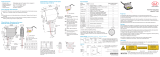
3. Functional Principle, Technical Data
3.1 Short Description
The interferoMETER measuring system includes:
- IMP-DS or IMP-TH sensor
- IMC5x00 controller
The sensor is completely passive as it contains no heat sources or moving parts. This prevents any heat-related expansion,
and ensures high precision of the measuring system.
The controller uses a spectrometer to convert any light signals that it receives from the sensor. It then calculates distance
values using the integrated signal processor (CPU) and transfers the data via its interfaces or the analog output.
CPU
Synchronization,
Trigger,
Encoder
SLED light source
DA converter
RS422 and
Ethernet /EtherCAT
Analog output U / I
Measuring object
IMC 5x00
Controller
Optical fiber
Sensor with
reference
Spectrometer
Fig. 1 Block diagram IMS5x00
3.2 Measuring Principle
Polychromatic white light is generated by an SLED. The light is coupled into an optical fiber. With a sensor for distance
measurement, the light of the fiber is separated by a beam splitter. Part of it radiates a firmly installed reference object.
The other part radiates the measurement object. The light reflected by both the reference and measurement object is
received by the sensor and conducted into the controller.
This is followed by the spectral decomposition and radiation of the detector. The light reflected by both the reference
object and the measurement object overlaps. The interferometric measuring principle (superposition of waves) is used.
Detection of distances and thicknesses is possible with amplification and elimination.
With a sensor for thickness measurement, the reference is omitted. This is why no distance measurement is possible.
i
Sensor and controller are one unit, as the sensor’s linearization table is stored in the controller.
This unique measuring system allows for highly precise measurement of targets. It is possible to measure both diffuse
and reflecting surfaces. For transparent layer materials, thickness measurements can be conducted in addition to dis-
tance measurements. Shadowing is avoided because sender and receiver are aligned along one axis.
The excellent resolution and the small beam spot diameter make it possible to measure surface structures. However,
measurement deviations may occur if the structure is of a similar size to the beam spot diameter or if the maximum tilt
angle is exceeded (e.g., with groove edges).

Page 11
Functional Principle, Technical Data
IMS5x00
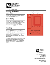
3.3 Term Definitions
SMR Start of measuring range. Minimum distance between sensor surface and target
MMR Mid of measuring range (=start of measuring range + 0.5*measuring range)
EMR End of measuring range (=start of measuring range + measuring range)
Maximum distance between sensor face and target
MR Measuring range
100 %
50
0
Sensor
SMR
SMR MMR EMR
Displacement
Signal
Target
Measuring range (MR)
Fig. 2 Distance sensor, measuring range and output signal at the controller
Thickness sensor
Working distance
Operating range
Fig. 3 Thickness sensor with working distance and operating range
3.4 Operating Modes
The interferoMETER measuring system provides highly accurate measurements of
- distances against visually dense materials with light-diffusing or reflective surfaces
- thicknesses for transparent layer materials.
By selecting the sensor, the distance or thickness measurement operating mode is selected. Accordingly, the result of
the measurement is a distance or thickness value.
Distance measurements Thickness measurements
Measuring range 2.1 mm 35 µm
1
... 1.4 mm
Fig. 4 Measuring ranges for distance and thickness measurements
The possible resolution here is in the nanometer range.
1) Measuring range with n=1.5; for air gap measurement between two glass plates (n~1) the measuring range is
0.05 ... 2.1 mm. The measurement object must be within the working distance.
3.5 Sensors
The controller can be operated with up to 20 different sensors.
The required calibration tables are stored within the controller.

Page 12
Functional Principle, Technical Data
IMS5x00
3.6 Technical Data
Model IMS5400-DS
Measuring range 2.1 mm
Start of measuring range approx. 19 mm
Resolution
1
< 1 nm
Measuring rate continuously adjustable from 100 Hz to 6 kHz
Linearity
2
< ±50 nm
Temperature stability
Linearity typ. 0.1 nm / K (without offset displacement)
temperature-compensated, stability < 10 ppm between +15 … +35 °C
Light source NIR-SLED, wavelength 840 nm
Laser safety class Class 1 in accordance with DIN EN 60825-1: 2015-07
Light spot diameter
3
10 µm
Max. tilt angle
4
±2°
Target material Glass, reflecting or diffuse surfaces
5
Supply voltage 24 VDC ±15 %
Power consumption approx. 10 W (24 V)
Signal input Sync in, Trigger in, 2 x encoders (A+, A-, B+, B-, index)
Digital interface Ethernet / EtherCAT / RS422
Analog output 4 … 20 mA / 0 ... 10 V (16 bit D/A converter)
Switching output Error1-Out, Error2-Out
Digital output Sync out
Connection
optical
pluggable optical fiber via E2000 socket (controller) and FC socket (sensor);
standard length 3 m, 5 m and 10 m; other cable lengths on request;
bending radius: static 30 mm, dynamic 40 mm
electrical
3-pin supply terminal strip;
encoder connection (15-pin, HD-sub socket, max. cable length 3 m,
30 m with external encoder supply);
RS422 connection socket (9-pin, Sub-D, max. cable length 30 m);
3-pin output terminal strip (max. cable length 30 m); 11-pin I/O terminal strip (max. cable length
30 m);
RJ45 socket for Ethernet (out) / EtherCAT (in/out) (max. cable length 100 m)
Installation
Sensor Clamping, mounting adapter (see accessories)
Controller free-standing, DIN rail mounting
Temperature range
Storage -20 … +70 °C
Operation
Sensor: +5 … +70 °C;
Controller: +15 … +35 °C
Shock (DIN-EN 60068-2-27) 15 g / 6 ms in XY axis, 1000 shocks each
Vibration (DIN-EN 60068-2-6) 2 g / 20 … 500 Hz in XY axis, 10 cycles each
Protection class (DIN-EN 60529) IP40 (controller and sensor)
Material
Sensor Stainless steel
Controller Aluminum housing, passive cooling
Control and display elements
multifunction button: two adjustable functions and reset to factory setting after 10 s;
web interface for setup: selectable presets, freely selectable averaging possibilities,
data reduction, setup management;6 x color LEDs for intensity, range, SLED, pilot laser, status
and power;switchable pilot laser for sensor alignment
(laser LED 635 nm, laser class 1, performance < 0.2 mW)
All data at constant ambient temperature (24 ±2 °C)
1) Measuring rate 0.5 kHz, moving averaging over 64 values, measured at the front of a glass plate in the mid of
the measuring range (2 sigma)
2) Maximum deviation from reference system over the entire measuring range, measured on front surface of ND filter
3) In the mid of the measuring range
4) Maximum sensor tilt angle that produces a usable signal on polished glass (n = 1.5) in the mid of the measuring range. The accu-
racy decreases when approaching the limit values.
5) Non-transparent materials require an optically dense surface with a wavelength of 840 nm

Page 13
Functional Principle, Technical Data
IMS5x00
Model IMS5600-DS
Measuring range 2.1 mm
Start of measuring range approx. 19 mm
Resolution
1
< 30 pm
Measuring rate continuously adjustable from 100 Hz to 6 kHz
Linearity
2
< ±10 nm
Temperature stability
Linearity: typ. 0.1 nm / K (without offset displacement)
temperature compensated, stability < 10 ppm between +15 … +35 °C
Light source NIR-SLED, wavelength 840 nm
Laser safety class Class 1 in accordance with DIN EN 60825-1 : 2015-07
Light spot diameter
3
10 µm
Max. tilt angle
4
±2°
Target material Glass, reflecting or diffuse surfaces
5
Supply voltage 24 VDC ±15 %
Power consumption approx. 10 W (24 V)
Signal input sync in, trigger in, 2 x encoders (A+, A-, B+, B-, index)
Digital interface Ethernet / EtherCAT / RS422
Analog output 4 … 20 mA / 0 … 10 V (16 bit D/A converter)
Switching output Error1-Out, Error2-Out
Digital output sync out
Connection
optical
pluggable optical fiber via E2000 socket (controller) and FC socket (sensor);
standard length 3 m, 5 m and 10 m; other cable lengths on request;
bending radius: static 30 mm, dynamic 40 mm
electrical
3-pin supply terminal strip; encoder connection
(15-pin, HD-sub socket, max. cable length 3 m, 30 m with external encoder supply);
RS422 connection socket (9-pin, Sub-D, max. cable length 30 m);
3-pin output terminal strip (max. cable length 30 m); 11-pin I/O terminal strip (max. cable length
30 m);RJ45 socket for Ethernet (out) / EtherCAT (in/out) (max. cable length 100 m)
Installation
Sensor Clamping, mounting adapter (see accessories)
Controller free-standing, DIN rail mounting
Temperature range
Storage -20 … +70 °C
Operation
sensor: +5 … +70 °C;
controller: +15 … +35 °C
Shock (DIN-EN 60068-2-27) 15 g / 6 ms in XY axis, 1000 shocks each
Vibration (DIN-EN 60068-2-6) 2 g / 20 … 500 Hz in XY axis, 10 cycles each
Protection class (DIN-EN 60529) IP40 (controller and sensor)
Vacuum optional UHV (cable and sensor)
Material
Sensor Stainless steel
Controller Aluminum housing, passive cooling
Control and display elements
multifunction button: two adjustable functions and reset to factory setting after 10 s;
web interface for setup: selectable presets, freely selectable averaging possibilities,
data reduction, setup management; 6 x color LEDs for intensity, range, SLED, pilot laser, status
and power;pilot laser: switchable for sensor alignment (laser LED 635 nm, laser class 1, perfor-
mance < 0.2 mW)
All data at constant ambient temperature (24 ±2 °C)
1) Measuring rate 0.5 kHz, moving average over 64 values, measured differentially between the front and back of a thin glass plate in
the mid of the measuring range (2 sigma)
2) Maximum deviation from reference system over entire measuring range, measured on front surface of ND filter
3) In the mid of the measuring range
4) Maximum sensor tilt angle that produces a usable signal on polished glass (n = 1.5) in the mid of the measuring range.
The accuracy decreases when approaching the limit values.
5) Non-transparent materials require an optically dense surface with a wavelength of 840 nm

Page 14
Functional Principle, Technical Data
IMS5x00
Model IMS5400-TH
Working distance 45 mm ±3.5 mm
Measuring range (thickness) 0.035 … 1.4 mm
1
Resolution
2
< 1 nm
Measuring rate continuously adjustable from 100 Hz to 6 kHz
Linearity
3
< ±100 nm
Temperature
stability
Sensor Linearity valid for the entire temperature range
Controller temperature compensated, stability < 10 ppm between +15 ... +35 °C
Light source NIR-SLED, wavelength 840 nm
Laser safety class Class 1 in accordance with DIN EN 60825-1 : 2015-07
Light spot diameter
4
10 µm
Max. tilt angle
5
±2°
Supply voltage 24 VDC ±15 %
Power consumption approx. 10 W (24 V)
Signal input sync in, trigger in, 2x encoders (A+, A-, B+, B-, index)
Digital interface Ethernet / EtherCAT / RS422
Analog output 4 … 20 mA / 0 ... 10 V (16 bit D/A converter)
Switching output Error1-Out, Error2-Out
Digital output sync out
Connection
optical
pluggable optical fiber via E2000 socket (controller) and FC socket (sensor);
standard length 3 m, 5 m and 10 m; other cable lengths on request;
bending radius: static 30 mm, dynamic 40 mm
electrical
3-pin supply terminal strip;
encoder connection (15-pin, HD-sub socket, max. cable length 3 m,
30 m with external encoder supply);
RS422 connection socket (9-pin, Sub-D, max. cable length 30 m);
3-pin output terminal strip (max. cable length 30 m);
11-pin I/O terminal strip (max. cable length 30 m);
RJ45 socket for Ethernet (out) / EtherCAT (in/out) (max. cable length 100 m)
Installation
Sensor Clamping, mounting adapter (see accessories)
Controller free-standing, DIN rail mounting
Temperature range
Storage -20 … +70 °C
Operation
Sensor: +5 … +70 °C;
Controller: +15 … +35 °C
Shock (DIN-EN 60068-2-29) 15 g / 6 ms in XY axis, 1000 shocks each
Vibration (DIN EN 60068-2-6) 2 g / 20 … 500 Hz in XY axis, 10 cycles each
Protection class (DIN-EN60529) IP40 (controller and sensor)
Vacuum optional UHV (cable and sensor)
Material
Sensor Stainless steel
Controller Aluminum housing, passive cooling
Control and display elements
multifunction button: two adjustable functions and reset to factory setting after 10 s;
web interface for setup: selectable presets, freely selectable averaging possibilities,
data reduction, setup management; 6 x color LEDs for intensity, range, SLED, pilot laser, status
and power; pilot laser: switchable for sensor alignment
(laser LED 635 nm, laser class 1, performance < 0.2 mW)
All data at constant ambient temperature (24 ± 2 °C)
1) Measuring range with n=1.5; for air gap measurement between two glass plates (n~1) the measuring range is 0.05 ... 2.1 mm.
The measurement object must be within the working distance.
2) Measuring rate 0.5 kHz, moving averaging over 64 values, measured on an approx. 1 mm thick BK7 optical flat (2 sigma)
3) Maximum thickness deviation when measuring on an approx. 1 mm thick BK7 optical flat (n=1.5) when passing through the mea-
suring range
4) With working distance = 45 mm
5) Maximum sensor tilt angle that produces a usable signal on an approx. 0.6 mm thick BK7 optical flat in the mid of the measuring
range. The accuracy decreases when approaching the limit values.

Page 15
Delivery
IMS5x00
4. Delivery
4.1 Unpacking/Included in Delivery
1 Controller IMC5x00
1 Sensor with sensor cable IMP-DSxx / IMP-THxx (inclusive optical fiber)
1 Accessory IMS5x00 (terminal blocks, Ethernet cables, mounting adapters, etc.)
1 Acceptance report
Carefully remove the components of the measuring system from the packaging and ensure that the goods are for-
warded in such a way that no damage can occur.
Check the delivery for completeness and shipping damage immediately after unpacking.
If there is damage or parts are missing, immediately contact the manufacturer or supplier.
4.2 Storage
Temperature range storage: -20 ... +70 °C (-4 ... +158 °F)
Humidity: 5 - 95 % (non-condensing)

Page 16
Installation
IMS5x00
5. Installation
5.1 IMC5x00 Controller
Place the IMC5x00 controller on a level surface or install it, e.g., in a control cabinet using a mounting rail (top-hat rail
TS35) according to DIN EN 60715 (DIN rail).
When mounting the controller onto a DIN rail, an electrical connection (potential equalization) is established between the
controller housing and the mounting rail.
To remove the controller, push it upwards and pull it forwards.
i
Position the controller so that the connections, controls and displays are not concealed.
218 (8.58)
120 (4.72)
124 (4.88)
(Feeds can be removed)
Fig. 5 Dimensional drawing, front view of IMC5x00 controller, dimensions in mm (inches)
76.2 (3.00)
81.2 (3.20)
appr. 63 (2.48)
Sensor
cable
Other cables:
less space
DIN rail
fastener
appr. 75 (2.95)
R
30
Fig. 6 Dimensional drawing, side view of IMC5x00 controller, dimensions in mm (inches)

Page 17
Installation
IMS5x00
5.2 Controller Operating Elements
1 2 3
45678910
Fig. 7 Front view of IMC5x00 controller
1
Multifunction button (light source)
1
6 Ethernet/EtherCAT
2 LED Status 7 Digital I/O
3 LEDs intensity, range, pilot laser, SLED 8 RS422 connection
4 Sensor connection channel 1 (optical fiber) 9 Encoder connection
5 Power supply connection, LED Power On 10 Analog output (U / I)
1) Resetting to factory settings: press the Multifunction button for more than 10 sec.

Page 18
Installation
IMS5x00
5.3 LEDs Controller
Power on Green Operating voltage available
Status
Off No error
If EtherCAT is active, meaning of the LED is conform with the EtherCAT guidelines.
Intensity
Red Signal in saturation
Yellow Signal too low
Green Signal ok
Range
Red No target object, or target object outside the measuring range
Yellow Target close to mid of measuring range
Green Target within measuring range
SLED
Red SLED off
Yellow SLED warms up
Green SLED ready for operation
Yellow flashing SLED current outside the optimal value range
1
Pilot
Red Pilot laser off
Green Pilot laser on
Green
Pilot laser is alternately turned on and off, if no target object or
outside the measuring range
Fig. 8 Meaning of the controller LEDs
1) When measuring outside the optimum current value of the SLED, the controller will measure, but the measurement
accuracy may not be as specified.
The LED’s Intensity and Range flashes with their current color during a synchronization error.

Page 19
Installation
IMS5x00
5.4 Electrical Connections Controller
5.4.1 Handling of Pluggable Screw Terminals
The IMC5x00 controller has three pluggable screw terminals for supply, digital I/O and analog out, which are included as
accessories.
Remove approx. 7 mm of the connecting wire insulation (0.14 ... 1.5 mm²).
Connect the connecting wires.
i
Use two captive screws to fix the screw terminals.
5.4.2 Grounding, Shielding
All inputs/outputs are electrically connected to the supply voltage ground (GND). Only the Ethernet/EtherCAT ports are
electrically isolated.
The ground connections (GND. GND422, GND_ENC) of each connection group are galvanically interconnected via
chokes.
The Shield connections of each connection group are only connected with the controller housing and are used for cable
screen connections with individual connections (power, analog output, switching outputs, synchronization and trigger
input).
Only use screened cables shorter than 30 m and connect the cable screen to the Shield or the connector housing.
5.4.3 Supply Voltage (Power)
CAUTION
Observe the safety instructions when handling supply voltage. Injury possible.
- 3-pin pluggable screw terminal (24 VDC,
GND, Shield),
- 24 VDC
± 15 %, I
max
<1 A
- not electrically separated, GND is elec-
trically connected to GND for switching
outputs, synchronization and encoder
input.
Use shielded cable with a length
< 30 m.
Fig. 9 Supply connections and LED on the
IMC5x00 controller
After the supply voltage has been switched on, the Power LED lights up.
5.4.4 RS422
- Differential signals in accordance with EIA-422, electrically isolated from the supply voltage.
- Receiver Rx with a 120 ohm internal terminating resistor.
Terminate the transmitter input (TX)
with 90 ...120 ohm on the evaluation
unit (receiver).
Use a shielded twisted cable. Cable
length less than 30 m.
Connect the ground connec-
tions.
i
The pin assignment for the 9-pin
D-sub socket is not standardized.
Pin Name Signal
3 RX - Receiver -
2 RX + Receiver +
5 GND422
RS422
ground
9 TX + Transmitter +
1 TX - Transmitter -
Housing Shield Cable shield
Fig. 10 Pin assignment for the 9-pin D-sub
connector (RS422)

Page 20
Installation
IMS5x00
5.4.5 Ethernet, EtherCAT
Potential-separated RJ 45 standard socket for connecting
the IMC5x00 controller
- to an Ethernet network (PC) or
- the EtherCAT bus system (IN-Port).
Use a shielded Ethernet cable (Cat5E, patch cable,
2 m, included in the delivery), overall cable length
less than 100 m to connect controller and net-
work.
Both LEDs in each of the plug-in connectors indicate a
successful connection and its activity.
Fig. 11 Connectors RJ45 for
Ethernet, EtherCAT
The controller can be configured using
- the web interface, see Chap. 6., see Chap. 7.,
- ASCII commands, see Chap. A 3or
- EtherCAT, see Chap. A 4.
5.4.6 Analog Output
The analog output can be used via the 3-pin screw terminal and is electrically connected to the supply voltage. For the
output, you can select current or voltage, see Chap. 7.5.4.
Voltage: Pin U/I
out
and Pin GND,
R
i
approx. 50 Ohm, R
L
> 10 MOhm
Slew rate (no C
L
, R
L
≥ 1 kOhm) typ. 0.5 V/µs
Slew rate (with C
L
= 10 nF, R
L
≥ 1 kOhm) typ. 0.4 V/µs
Current: Pin U/I
out
and Pin GND
R
L
≤ 500 Ohm
Slew rate (no C
L
, R
L
= 500 Ohm) typ. 1.6 mA/µs
Slew rate (with C
L
= 10 nF, R
L
= 500 Ohm) typ. 0.6 mA/µs
Fig. 12 Analog outputs on
the controller
Use a shielded cable. Cable length less than 30 m.
Pin 3 (Shield) is connected to the cover.
Alternatively, the following values may be defined for the output range:
Voltage: 0 ... 5 V; 0 ... 10 V;
Current: 4 ... 20 mA.
i
The socket is mechanically coded (red plug-in) in order to avoid any confusion with the power supply.
/