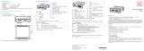
MICRO-EPSILON optoNCDT 2300DR Assembly Instructions
- Type
- Assembly Instructions

Assembly Instructions
optoNCDT 2300-2DR
Proper Use
The optoNCDT 2300-2DR system is designed for use in industrial and laboratory areas.
It is used for measuring displacement, distance, position and elongation for in-process quality con-
trol and dimensional testing
The sensor may only be operated within the limits specified in the technical data, see instruction
manual, Chap. 3.4. Use the sensor in such a way that in case of malfunctions or failure personnel or
machinery are not endangered.
Take additional precautions for safety and damage prevention for safety-related applications.
Warnings
Avoid unnecessary laser radiation to be exposed to the human body. Switch off the sensor for clean-
ing and maintenance, for system maintenance and repair if the sensor is integrated into a system.
Caution - use of controls or adjustments or performance of procedures other than those specified
may cause harm.
Connect the power supply and the display-/output device in accordance with the safety regulations
for electrical equipment. The power supply may not exceed the specified limits.
> Danger of injury. Damage to or destruction of the sensor.
Avoid continuous exposure to fluids on the sensor. Avoid exposure to aggressive materials (washing
agent, penetrating liquids or similar) on the sensor.
> Damage to or destruction of the sensor.
Avoid shock and vibration to the sensor. Protect the sensor cable against damage.
> Damage to or destruction of the sensor , failure of the measuring device.
Laser Class
The optoNCDT 2300-2DR sensors operate with a semiconductor laser with a wavelength of 405 nm
(visible/blue ILD 2300-xBL).
The following warning labels are attached to the cover (front and/or rear side) of the sensor housing:
LASER RADIATION
Do not stare into beam
Class 2 Laser Product
IEC 60825-1: 2014
P 1mW; P 1.2mW; t=0.5...542 s
0 P
≤ ≤ μ
F=1.5...50kHz;
=405nm
COMPLIES WITH 21 CFR 1040.10 AND 1040.11
EXCEPT FOR CONFORMANCE WITH
IEC 60825-1 ED. 3., AS DESCRIBED IN
LASER NOTICE NO. 56, DATED MAY 8, 2019
IEC label Only for USA
Never deliberately look into the laser beam! Consciously close your eyes or
turn away immediately if ever the laser beam should hit your eyes.
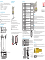
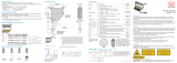
Input and Output
Signal
Designation
Sensor
Pin
Comment
Cable PC2300-x/SUB-D
1
15-pol. Sub-D
+ U
b
1 Supply voltage (11 ... 30 VDC) 1
Ground 2
System ground for supply and ground poten-
tial for RS422-level
9
+Laser on/off
3
optocoupler input, potential-free
Laser off: U
E
≤ 0,8 V (Low)
Laser on: 2,8 V ≤ U
E
≤ 30 V (High)
2
- Laser on/off
4 10
Sync-in/out
2
5
Synchronous- respectively trigger signals,
symmetrically, RS422 level, terminating
resistor 120 Ohm switchable, input or output
selected depending on the synchronization
mode
3
/Sync-in/out
2
6 11
RxD-RS422 7
Serial input RS422, symmetrically,
Internally terminated with 120 Ohm
4
/RxD-RS422 8 12
TxD-RS422 9
Serial output RS422, symmetrically
5
/TxD-RS422 10 13
Tx - Ethernet 11
Ethernet output, potential-free
6
/Tx - Ethernet 12 14
Rx - Ethernet 13
Ethernet input, potential-free
7
/Rx - Ethernet 14 15
Screen Housing No galvanic connection to ground Housing
1) Further cables are available optionally.
2) In trigger operation the input is used for triggering.
Plug connector: ODU MINI-SNAP, 14 pin, series B, dimension 2,
code F, IP 68. Sensor round pin plug, view: Solder-pin side male cable
connector
1
2
3
4
5
6
7
8
9
10
11
12
13
14
Supply Voltage, Nominal value: 24 V DC (11 ... 30 V, max. 150 mA).
ILD 2300
1
2
11 ...
30 VDC
Sensor
Pin
PC2300-x/Y
Color
Supply
Use supply voltage for measurement
instruments only. MICRO-EPSILON
recommends using an optional available
power supply unit PS2020 for the sensor.
1 white +U
B
2 brown Ground
Laser on
PC2300-x/Y
+U
3
4
brown
2
1
max.
30 V
ca. 5 mA
Type 1
ILD 2300
B
Laser off:
U
OUT
< 0.8 V
Laser on:
2.8 V < U
OUT
< 30 V
white
green
yellow
Ground
MICRO-EPSILON MESSTECHNIK
GmbH & Co. KG
Königbacher Str. 15 · 94496 Ortenburg
www.micro-epsilon.com
X9771234.01-A021079SWE
i
If pin Pin 3 with +U
B
and Pin 4 are
not connected with ground, the
laser is off.
Proper Environment
- Protection class: IP 65 (applies only when the sensor cable is plugged in)
Lenses are excluded from protection class. Contamination of the lenses leads to impairment or
failure of the function.
- Operating temperature: 0 °C ... 50 °C (+32 up to +104 °F)
- Storage temperature: -20 °C ... 70 °C (-4 up to +158 °F)
- Humidity: 5 - 95 % (no condensation)
- Ambient pressure: Atmospheric pressure
Sensor Mounting, Diffuse Reflection
The optoNCDT 2300-2DR sensor is an optical system for measurements with micrometer
accuracy.
i
Make sure it is handled carefully when installing and operating!
Mount the sensor only to the existing holes on a flat surface. Clamps of any kind are not
permitted.
Mount the sensor by means of 3 screws type M3. The bearing surfaces surrounding the
fastening holes (through-holes) are slightly raised.
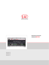
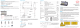
Direct Reflection, Mounting,
Measuring range 2 mm
Direct reflection
Mounting steps
Switch on the supply voltage on the sensor.
Watch the “State“ LED on the top side of the sensor.
Position a shining or mirroring measuring object within the measuring range.
Move the fit-up aid between sensor and measuring object.
The “State“ LED illuminates yellow.
Mount the sensor by means of 3 screws type M4.
Remove the fit-up aid between sensor and measuring object.
In case of bore holes, blind holes, and edges in the surface of moving targets the sensor must be
arranged in such a way that the edges do not obscure the laser spot.
Correct
Incorrect
(shadow)
Direct Reflection, Dimensions,
Measuring range 2 mm
*X9771234.01-A02*
MR = Measuring range
93 (3.66)
86 (3.39)
40.5 (1.59) 45.5 (1.79)
MR = 2
10 (.39)
17 x 45°
30 (1.18)
15
(.59)
88 (3.46)
3.5
(.14)
3.5
(.14)
95 (3.74)
90°

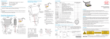
Quick Guide
Components
- Sensor
- Power supply
- Laptop / PC + USB/Ethernet adapter + Ethernet cable
Mount the sensor and connect the components together.
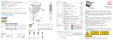
Ethernet Connection
PC2300-0.5/YPC2300-x/SUB-D
Patch cable
PS2020
230 VAC
PE
N L
PS2020
Measuring object
optoNCDT
BL
ERR
Power on
RUN
EtherCAT Ethernet
Error
Laser off
In range
Midrange
LASER RADIATION
Do not stare into beam
Class 2 Laser Product
IEC 60825-1: 20xx-xx
P 1mW; P 1.2mW; t=0.5...542 s
0 P
≤ ≤ μ
F=1.5...50kHz;
=405nm
EtherCAT Connection
PC2300-0.5/YPC2300-x/SUB-D
PS2020
230 VAC
PE
N L
PS2020
Run
BECKHOFF EK1122
X1
X2
Patch cable
Measuring object
optoNCDT
BL
ERR
Power on
RUN
EtherCAT Ethernet
Error
Laser off
In range
Midrange
LASER RADIATION
Do not stare into beam
Class 2 Laser Product
IEC 60825-1: 20xx-xx
P 1mW; P 1.2mW; t=0.5...542 s
0 P
≤ ≤ μ
F=1.5...50kHz;
=405nm
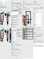
Commissioning
The sensor is delivered ex factory with the IP address
169.254.168.150.
You can check the IP address of the sensors, that are connected
to a PC / network, with the
SensorFinder.exe. program. You will find this program on the
provided CD.
Now start the program SensorFinder.exe and click on the
button Start scan.
Select the designated sensor from the list.
Click the button Start
browser to connect the
sensor with your default
browser.
Alternatively: If DHCP is
enabled and the DHCP
server is linked with the DNS
server, an access is possible
on „ILD2300_SN01234567“
(„01234567“ Serial number of
your sensor).
Start a web browser on your PC. Type
„ILD2300_Serial number“ in the address bar of
your web browser.
Interactive websites for programming the sensor
now appear in the web browser.
If you have changed any settings, go to the
menu Preferences and click on the button
Save Setup to store your settings.
Select a Measuring Program
Go to the menu Preferences > Measuring program.
Select Diffuse reflection from the measurement arrangement list. Confirm with Apply.
Select a Measuring Rate
Go to the menu Preferences > Measuring rate.
Start with a medium measuring rate. Select a measuring rate from the list. Confirm with Apply.
Select a Digital Interface
Go to the menu Preferences > Digital interfaces > Selection of digital
interfaces.
Select Web Diagram from the list. Confirm with Apply.
Store the Settings
Go to the menu Preferences > Load/save settings.
Select Parameter set from the data selection list, a parameter set number and click on the
button Save.
Position a Measuring Object
Position a measuring object (target) as possible in the midrange.
100 %
50
0
SMR
SMR MMR EMR
Displacement
Signal
Measuring object
Measuring range
optoNCDT
BL
ERR
Power on
RUN
EtherCAT Ethernet
Error
Laser off
In range
Midrange
LASER RADIATION
Do not stare into beam
Class 2 Laser Product
IEC 60825-1: 20xx-xx
P 1mW; P 1.2mW; t=0.5...542 s
0 P
≤ ≤ μ
F=1.5...50kHz;
=405nm
The Status LED Status on the sensor indicates the position of the measuring object to the sensor.
LED Color Labeling Meaning
Status
off Laser off Laser beam is switched off
green In range Sensor operates, measuring object within measuring range
yellow Midrange Measuring object is in midrange
red Error
Measuring object outside measuring range,
reflection is to low
Displacement Measuring
Go to the menu Measurement.
Disable the Autoscale function and click on the Start button.
Thickness Measurement
Got to the menu Preferences > Measuring program and select Direct reflec-
tion - thickness measurement from the measurement arrangement list.
Select the target material from the material list. Confirm with Apply.
Store the Settings
Go to the menu Preferences > Load/save settings.
Select Parameter set from the data selection list, a parameter set number and click on
the button Save.
Read the detailed instruction manual before using the sensor. The manual is available online on
www.micro-epsilon.com/download/manuals/man--optoNCDT-2300--en.pdf or on the supplied CD.
-
 1
1
-
 2
2


MICRO-EPSILON optoNCDT 2300DR Assembly Instructions
- Type
- Assembly Instructions
Ask a question and I''ll find the answer in the document
Finding information in a document is now easier with AI
Related papers
-
 MICRO-EPSILON optoNCDT 2300 Assembly Instructions
-
 MICRO-EPSILON optoNCDT 2300 User manual
-
 MICRO-EPSILON interferoMETER IMS5400-DS IMS5600-DS IMS5400-TH User manual
-
 MICRO-EPSILON C-Box/2A Assembly Instructions
-
 MICRO-EPSILON software Disc Thickness Variation Measurement Owner's manual
-
 MICRO-EPSILON optoNCDT 1750 Housing S Assembly Instructions
-
 MICRO-EPSILON optoNCDT 1750 User manual
-
 MICRO-EPSILON optoNCDT 1750 Housing M Assembly Instructions
-
 MICRO-EPSILON optoNCDT 1700 Assembly Instructions
-
 MICRO-EPSILON optoNCDT 1750 Housing S Assembly Instructions