Page is loading ...

Assembly Instructions
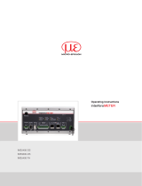
IF2035
EtherCAT
Intended Use
The IF2035-EtherCAT interface module is designed for use in industrial and laboratory applications. It
is used to convert the internal MICRO-EPSILON sensor protocol (RS485, RS422) to EtherCAT.
The interface module must only be operated within the limits specified in the technical data. The in-
terface module must be used in such a way that no persons are endangered or machines and other
material goods are damaged in the event of malfunction or total failure of the sensor/controller. Take
additional precautions for safety and damage prevention in case of safety-related applications.
Warnings
Connect the power supply and the display/output device according to the safety regulations for
electrical equipment.
> Risk of injury
> Damage to or destruction of the interface module
The supply voltage must not exceed the specified limits.
> Damage to or destruction of the interface module
Avoid shocks and impacts to the interface module.
> Damage to or destruction of the interface module
Proper Environment
Protection class: IP 20
Operating temperature: 0 ... +50 °C
Storage temperature: -20 ... +70 °C
Humidity: 5 - 95 % (non-condensing)
Ambient pressure: Atmospheric pressure
Connection Options
ACS7000
IFC24x1, IFC242x
ILD1x20
ILD1750
ILD1900
ILD2300
ILR2250
MFA-xx
ODC2520
Cable
CAB-M9-5P-St-ge; xm-PVC-RS422
SC2471-x/RS422/OE
Direct or PCF1420-x/I/U
PC1700-x/OE
Sensor/
Controller
PC2300-x/OE
RS485 RS422
ACC5703
DT6120
INC5701
PCx/8-M12
Cable
SCAC3/6
PCx/8-M12
Sensor/
Controller
PC1900-x/OE
MSC7602
MSC7602
Connector kit
CAB-M12-8P-St-ge-x
PC/SC2520-x
PC2250-x
The maximum cable length between IF2035-EtherCAT and sensor/controller is 10 m. With the
ACC5703 and INC5701 sensors, sensor supply is only possible via the IF2035-EtherCAT because of
the PCx/8-M12 cable.
Standard Cabling
During cabling, channel 0 of the IO controller is connected to the input port of the first IO device
(slave device). The output port of the first slave device is connected to the input port of the next
slave device, etc. The output port of the last slave device and channel 1 of the master device remain
unused.
IO-Controller
IO-Device 1 IO-Device 2
Redundancy
IO-Device n
You achieve greater failsafe network performance if you implement an additional redundant con-
nection (MRP = Media Redundancy Protocol) between the output port of the last slave device and
channel 1 of the IO controller. IF2035-EtherCAT can participate in an MRP ring as a client; however,
it cannot manage the ring. To achieve ring functionality, all participants must be configured as ring
participants.
X9771462-A012033MSC
MICRO-EPSILON MESSTECHNIK GmbH & Co. KG
Königbacher Str. 15 • 94496 Ortenburg
e-mail [email protected]
www.micro-epsilon.com
Your local contact: www.micro-epsilon.com/contact/worldwide/
Installation and Assembly
i Ensure careful handling during installation and operation.
22.6
(.89)
-0,3
+0,35
99
(3.90)
±0,4
107
(4.21)
113.7 (4.48)Millimeter (Inches)
-0,4
+0,6
Pin assignment
Supply Voltage
The supply voltage is daisy-chained from the supply
port (terminal 1) to the sensor port (terminal 2), i.e., the
supply voltage must match that of the sensor. Positive
voltage must be between 9 V and 36 V.
Connect the inputs V+ and to terminal 1 with a
voltage supply. Maximum cable length 3 m.
MICRO-EPSILON recommends using an optional avail-
able power supply unit PS2020.
DC 24V 3.3A
N L
Power Supply
230 VAC PE
Cable Termination at Interface
i Ensure correct cable termination for an RS485 bus or RS422 bus! IF2035-EtherCAT works
as a master for both interfaces; internally, a 120 ohm terminating resistor has already been
permanently incorporated. The IF2035-EtherCAT should be at the bus start.
A
B
IF2030
RS485
Slave n
Slave n-1
n = max. 16 Slaves
120
Ohm
120
Ohm
RS422
RX+
RX -
IF2030 Slave 1
120
Ohm
120
Ohm
TX -
TX+
120
Ohm
120
Ohm
Terminal 1 Terminal 3
Terminal 2 Terminal 4
A B S S
T RRT
M1M2V
M1M2V
Terminal 2 Terminal 4
V+ Supply voltage 2T+ RS422 Tx+
Ground for supply voltage T- RS422 Tx-
M1 Multifunction input 1 R+ RS422 Rx+
M2 Multifunction input 2 R- RS422 Rx-
Terminal 1 connections daisy-chained Ground 1 e.g., for RS422 shield connection
Terminal 1 Terminal 3
V+ Supply voltage A RS485 A
Ground for supply voltage B RS485 B
M1 Multifunction input 1 S+ Synchronization output +
M2 Multifunction input 2 S- Synchronization output -
Terminal 2 connections daisy-chained Ground 1 e.g., for RS485 shield connection
1) Internally connected to supply ground 2) If the distance between IF2035-EtherCAT and the sensor/con-
troller is long, a separate supply for the sensor/controller may be
advisable.

Quick Guide
Configuring the Sensor Interface
Only sensors (controllers) that support the ME sensor protocol can be connected via RS485/RS422.
Micro-Epsilon recommends selecting the corresponding sensor interface via the web interface of the
sensor (controller).
Baudrate
There is no automatic baud rate matching between IF2035-EtherCAT and the connected sensor
(controller). MICRO-EPSILON recommends selecting the corresponding baud rate via the web inter-
face of the sensor (controller).
Data format
All configuration parameters and data are transmitted in Little Endian format.
Sensors/controllers with RS485: cyclical data are transmitted via the fieldbus without change, i.e., as
a binary block as described and supplied by the sensor.
Sensors/controllers with RS422: the cyclic data is decoded, i.e. a 4th byte is added to the 3 bytes
and then transmitted.
EtherCAT Configuration with the Beckhoff TwinCAT© Manager
As EtherCAT master on the PC, e.g. the TCXAEShell software from Beckhoff can be used.
This section requires that
- the TwinCAT XAE Shell software is installed on your PC,
- a sensor is connected to the PC via LAN,
- no TwinCAT project has been created.
The device description file (EtherCAT® slave information) IF2035_EtherCAT.xml is available online at
https://www.micro-epsilon.de/download/software.
Copy the device description file to the directory C:\TwinCAT\3.1\Config\Io\EtherCAT before the
measuring device can be configured via EtherCAT®.
Delete any existing older files.
EtherCAT®-Slave information files are XML files, which specify the characteristics of the Slave device
for the EtherCAT® Master and contain information on the supported communication objects.
Start the TwinCAT XAE Shell program.
Create a new project by
clicking the New TwinCAT
Project button.
Assign a name for the
project and choose a
suitable location.
Confirm with OK.
Searching for a device:
Switch to the Solution
Explorer window. In
the I/O tab, right-click on
the Devices entry, and
then Scan.
Confirm with OK.
Select a network card at
which EtherCAT® slaves
are to be searched for.
Confirm with OK.
The "Scan for boxes"
window appears (EtherCAT®
slaves).
Confirm with Yes.
The sensor is now listed in
the device list, see Solution
Explorer window.
Now confirm the Acti-
vate Free Run window
with Yes.
The current status should be
at least PREOP, SAFEOP or
OP on the Online page.
If ERR PREOP is displayed in
Actual State, the cause
is described in the message
window. The cause of the error
could be a discrepancy be-
tween the PDO mapping in the
controller and the settings in
the IF2035_EtherCAT.xml
device description file.
You can select other data in the Process Data tab.
The scope of the provided process data and the assignment of the SyncManager may be viewed
now.
Go to the TwinCAT menu and select the Restart TwinCAT (Config Mode) entry.
The configuration is now complete.
In SAFEOP and OP status, the selected measurement values are transferred as process data.
You can find more information about the sensor in the operating instruc-
tions. They are available online at:
www.micro-epsilon.de/download/manuals/man--IF2035-EtherCAT--en.pdf
/