Page is loading ...

Programming guide
Xr100 SerieS Canadian
Control Panel

MODEL XR100 SERIES CANADIAN
CONTROL PANEL PROGRAMMING GUIDE
Contains programming instructions for use with the
Model XR100 and XR100N Series Canadian Control Panel.
When using the XR100 Series Canadian panel for any ULC or other listing organization’s approved methods, refer to this
manual and the XR100 Series Canadian Installation Guide (LT-0899CAN). These documents outline the installation and
programming requirements of all applications for which the XR100 Series is approved.
INDUSTRY CANADA NOTICE
This Class A digital apparatus complies with Canadian ICES-003.
© 2015 Digital Monitoring Products, Inc.
Information furnished by DMP is believed to be accurate and reliable.
This information is subject to change without notice.

XR100 Series Canadian Programming Guide Digital Monitoring Products
i
Table Of COnTenTs
Introduction ......................................................................1
1.1 Before you Begin.......................................................................1
1.2 Getting Started .........................................................................1
1.3 Programmer Operation ..............................................................2
1.4 Programmer Lockout Codes .......................................................2
1.5 Reset Timeout ..........................................................................2
1.6 Power Up .................................................................................2
1.7 Keypads ..................................................................................3
1.8 Special Keys .............................................................................3
1.9 Entering Alpha Characters ..........................................................3
1.10 Entering Non-Alpha Characters ...................................................4
1.11 Keypad Displays Current Programming .......................................4
1.12 Asterisks in Programming ..........................................................5
Initialization......................................................................6
2.1 Initialization ..............................................................................6
2.2 Clear All Memory .......................................................................6
2.3 Clear All Codes ..........................................................................6
2.4 Clear All Schedules .................................................................... 6
2.5 Clear Display Events Memory .....................................................6
2.6 Clear Zone Information ..............................................................6
2.7 Clear Area Information ..............................................................6
2.8 Clear Output Information ........................................................... 6
2.9 Clear Communication and Remote Options ..................................7
2.10 Set to Factory Defaults ..............................................................7
Communication .................................................................8
3.1 Communication ......................................................................... 8
3.2 Account Number .......................................................................8
3.3 Transmit Delay .......................................................................... 8
3.4 Communication Path .................................................................8
3.5 Communication Type .................................................................8
3.6 Path Type .................................................................................9
3.7 Test Report ...............................................................................9
3.8 Test Frequency .........................................................................9
3.9 Test Day ................................................................................... 9
3.10 Test Time .................................................................................9
3.11 Check In ...................................................................................9
3.12 Fail Time ..................................................................................9
3.13 Receiver IP ...............................................................................9
3.14 Receiver Port .......................................................................... 10
3.15 First Telephone Number ........................................................... 10
3.16 Second Telephone Number ...................................................... 10
3.17 Advanced Programming ........................................................... 10
3.18 First GPRS APN ....................................................................... 10
3.19 Fail Test Hours ........................................................................ 10
3.20 Protocol .................................................................................. 11
3.21 Retry Seconds ......................................................................... 11
3.22 Substitution Code .................................................................... 11
3.23 893A ...................................................................................... 11
3.24 Alarm Switch .......................................................................... 11
3.25 Duplicate Alarms ..................................................................... 11
3.26 Alarm Reports ......................................................................... 11
3.27 Supervisory/Trouble Reports .................................................... 12
3.28 Opening/Closing and User Reports ........................................... 12
3.29 Door Access Report ................................................................. 12
3.30 Send Communication Trouble ................................................... 12
3.31 Send Path Information ............................................................. 12
Network Options (XR100N only) ....................................13
4.1 DHCP Mode Enabled ................................................................ 13
4.2 Local IP Address ..................................................................... 13
4.3 ........................................................................Gateway Address 13

Digital Monitoring Products XR100 Series Canadian Programming Guide
ii
Table of ConTenTs
4.4 Subnet Mask ........................................................................... 13
4.5 DNS Server ............................................................................. 13
4.6 734N Listen Port ..................................................................... 13
4.7 734/734N Passphrase .............................................................. 13
Messaging Setup .............................................................14
5.1 Messaging Setup ..................................................................... 14
5.2 Enable Messaging ................................................................... 14
5.3 System Name ......................................................................... 14
5.4 Destination 1 .......................................................................... 14
5.5 Destination 1 User Number ..................................................... 14
5.6 Destination 2 .......................................................................... 14
5.7 Destination 2 User Number ...................................................... 14
5.8 Destination 3 .......................................................................... 14
5.9 Destination 3 User Number ...................................................... 15
5.10 Email Communication Type ...................................................... 15
5.11 O/C Email ............................................................................... 15
5.12 O/C SMS ................................................................................. 15
5.13 Monthly Limit .......................................................................... 15
5.10 SMTP Server ........................................................................... 15
5.11 SMTP Server Port .................................................................... 15
5.12 SMTP Username ...................................................................... 15
5.13 SMTP Password ....................................................................... 15
5.14 From Email Address ................................................................ 15
Device Setup ...................................................................16
6.1 Device Setup .......................................................................... 16
6.2 Device Number ....................................................................... 16
6.3 Device Name .......................................................................... 16
6.4 Device Type ............................................................................ 16
6.5 Device Communication Type .................................................... 16
6.6 Wireless ................................................................................. 16
6.6.1 Serial Number ......................................................................... 16
6.6.2 Supervision Time .................................................................... 16
6.7 Access Areas ........................................................................... 16
6.8 Egress Areas ........................................................................... 17
6.9 Display Areas .......................................................................... 17
6.10 Strike Time ............................................................................. 18
6.11 Strike Delay ............................................................................ 18
6.12 Fire Exit Release ..................................................................... 18
6.13 Output Group ......................................................................... 18
6.14 Schedule Override ................................................................... 19
6.15 Auto Force Arm Device? ........................................................... 19
6.16 Door Real-Time Status? ........................................................... 19
6.17 Send Door Forced Message? .................................................... 19
6.18 Program 734/734N Options ...................................................... 19
6.18.1 Activate Zone 2 Bypass ............................................................ 19
6.18.2 Zone 2 Bypass Time ................................................................ 19
6.18.3 Relock on Zone 2 Change? ....................................................... 19
6.18.4 Activate Zone 3 Request to Exit ................................................ 20
6.18.5 Zone 3 REX Strike Time ........................................................... 20
6.18.6 Activate Onboard Speaker ........................................................ 20
6.18.7 Card Options .......................................................................... 20
6.18.8 Weigand Code Length ............................................................. 20
6.18.9 Site Code Position ................................................................... 21
6.18.10 Site Code Length..................................................................... 21
6.18.1 User Code Position .................................................................. 21
6.18.12 User Code Length ................................................................... 21
6.18.13 Require Site Code ................................................................... 21
6.18.13.1 Site Code Display .................................................................... 21
6.18.14 Number of User Code Digits ..................................................... 21
6.18.15 No Communication with Panel .................................................. 22

XR100 Series Canadian Programming Guide Digital Monitoring Products
iii
Table Of COnTenTs
Remote Options ..............................................................22
7.1 Remote Options ...................................................................... 22
7.2 Remote Key ............................................................................ 22
7.3 Remote Disarm ....................................................................... 22
7.4 Armed Answer Rings ............................................................... 22
7.5 Disarmed Answer Rings ........................................................... 22
7.6 PC Modem .............................................................................. 22
7.7 Alarm Receiver Authorization ................................................... 23
7.8 Service Receiver Authorization ................................................. 23
7.9 Manufacturer Authorization ...................................................... 23
7.10 Allow Network Remote ............................................................ 23
7.10.1 Network Programming Port ...................................................... 23
7.10.2 Encrypt Network Remote ......................................................... 23
7.11 Allow Cellular Remote .............................................................. 23
7.11.1 First GPRS APN ....................................................................... 23
7.11.2 Encrypt Cellular Remote .......................................................... 23
7.12 Entré Connection .................................................................... 24
7.12.1 Entré Incoming TCP Port ......................................................... 24
7.12.2 Entré IP Address ..................................................................... 24
7.12.3 Entré Outbound TCP Port ......................................................... 24
7.12.4 Entré Backup IP Address ......................................................... 24
7.12.5 Entré Backup TCP Port............................................................. 24
7.12.6 Entré Checkin ......................................................................... 24
7.12.7 Entré Passphrase .................................................................... 24
7.13 Send Local Changes ................................................................ 24
7.13.1 Remote Change IP .................................................................. 24
7.13.2 Remote Change Port ............................................................... 24
7.13.3 Remote Telephone Number ...................................................... 25
System Reports ...............................................................25
8.1 System Reports ....................................................................... 25
8.2 Abort Report ........................................................................... 25
8.3 Restoral Reports...................................................................... 25
8.5 Schedule Change Reports ........................................................ 25
8.6 Code Change Reports .............................................................. 25
8.7 Access Keypads ....................................................................... 26
8.8 Ambush .................................................................................. 26
System Options ...............................................................26
9.1 System Options ....................................................................... 26
9.2 System ................................................................................... 26
9.3 Instant Arming ........................................................................ 26
9.4 Closing Wait ........................................................................... 26
9.5 Entry Delay 1 .......................................................................... 27
9.6 Cross Zone Time ..................................................................... 27
9.7 Zone Retard Delay................................................................... 27
9.8 Power Fail Delay ..................................................................... 27
9.9 Swinger Bypass Trips ............................................................... 27
9.10 Reset Swinger Bypass .............................................................. 27
9.11 Time Zone Changes ................................................................. 27
9.12 Latch Supervisory Zones .......................................................... 28
9.13 Programming Menu Language .................................................. 28
9.14 User Menu and Status List Language ........................................ 28
9.15 Bypass Limit ........................................................................... 29
9.16 House Code ............................................................................ 29
9.17 Detect Wireless Jamming ......................................................... 29
9.18 Wireless Audible Annunciation .................................................. 29
9.19 Enable Keypad Panic Keys ........................................................ 30
9.20 Occupied Premise.................................................................... 30
9.21 Enhanced Zone Test ................................................................ 30
9.22 Dual EOL ................................................................................ 30
9.23 Send 16 Character Names........................................................ 30

Digital Monitoring Products XR100 Series Canadian Programming Guide
iv
Table of ConTenTs
9.24 Keypad Armed LED ................................................................. 30
9.25 Use False Alarm Question ........................................................ 30
Bell Options .....................................................................31
10.1 Bell Options ............................................................................ 31
10.2 Bell Cutoff Time ...................................................................... 31
10.3 Automatic Bell Test .................................................................. 31
10.4 Bell Output ............................................................................. 31
10.5 Bell Action .............................................................................. 31
10.5.1 Fire Bell Action ........................................................................ 31
10.5.2 Burglary Bell Action ................................................................. 31
10.5.3 Supervisory Bell Action ............................................................ 31
10.5.4 Panic Bell Action ..................................................................... 31
10.5.5 Emergency Bell Action ............................................................. 31
10.5.6 Auxiliary 1 Bell Action .............................................................. 31
10.5.7 Auxiliary 2 Bell Action .............................................................. 31
Output Options................................................................32
11.1 Output Options ....................................................................... 32
11.2.1 Cutoff Output ......................................................................... 32
11.2.2 Output Cutoff Time ................................................................. 32
11.3 Communication Trouble Output ................................................ 32
11.4 Fire Alarm Output ................................................................... 32
11.5 Fire Trouble Output ................................................................. 32
11.6 Panic Alarm Output ................................................................. 33
11.7 Ambush Output ....................................................................... 33
11.8 Entry Output ........................................................................... 33
11.9 Exit Output ............................................................................. 33
11.10 Ready Output ......................................................................... 33
11.11 Telephone Trouble Output ........................................................ 33
11.12 Late To Close Output ............................................................... 33
11.13 Device Fail Output ................................................................... 33
11.14 Sensor Reset Output ............................................................... 33
11.15 Closing Wait Output ................................................................ 34
11.16 Arm-Alarm Output ................................................................... 34
11.17 Supervisory Alarm Output ........................................................ 34
Output Information ........................................................35
12.1 Output Information ................................................................. 35
12.2 Output Number ....................................................................... 35
12.3 Output Name .......................................................................... 35
12.4 Output Real-Time Status .......................................................... 35
12.5 Serial Number ......................................................................... 35
12.6 Supervision Time .................................................................... 35
12.7 Trip with Panel Bell Option ....................................................... 35
Output Groups ................................................................36
13.1 Output Groups ........................................................................ 36
13.2 Group Number ........................................................................ 36
13.3 Group Name ........................................................................... 36
13.4 Output Number ....................................................................... 36
Menu Display ...................................................................37
14.1 Menu Display .......................................................................... 37
14.2 Armed Status .......................................................................... 37
14.3 Time ...................................................................................... 37
14.4 Arm/Disarm ............................................................................ 37
Status List .......................................................................38
15.1 Status List .............................................................................. 38
15.2 Display Keypads ...................................................................... 38
15.3 System Monitor Troubles.......................................................... 38
15.4 Fire Zones .............................................................................. 38
15.5 Burglary Zones ........................................................................ 39

XR100 Series Canadian Programming Guide Digital Monitoring Products
v
Table Of COnTenTs
15.6 Supervisory Zones ................................................................... 39
15.7 Panic Zones ............................................................................ 39
15.8 Emergency Zones .................................................................... 39
15.9 Auxiliary 1 Zones ..................................................................... 39
15.10 Auxiliary 2 Zones ..................................................................... 39
15.11 Communication Trouble ........................................................... 39
PC Log Reports ................................................................40
16.1 PC Log Reports ....................................................................... 40
16.2 Communication Type ............................................................... 40
16.3 Net IP Address ........................................................................ 40
16.4 Net Port ................................................................................. 40
16.5 Arm and Disarm Reports .......................................................... 40
16.6 Zone Reports .......................................................................... 40
16.7 User Command Reports ........................................................... 40
16.8 Door Access Reports ............................................................... 40
16.9 Supervisory Reports ................................................................ 41
16.10 PC Log Real-Time Status .......................................................... 41
Area Information ............................................................42
17.1 Area Information ..................................................................... 42
17.2 Exit Delay ............................................................................... 42
17.3 Burglary Bell Output ................................................................ 42
17.4 Opening/Closing Reports ......................................................... 42
17.5 Closing Check ......................................................................... 43
17.6 Closing Code ........................................................................... 43
17.7 Any Bypass ............................................................................. 43
17.8 Area Schedules ....................................................................... 43
17.9
Area Number .......................................................................... 43
17.9.1
All/Perimeter Programming ...................................................... 43
17.9.2
Home/Sleep/Away Programming .............................................. 43
17.10 Area Name ............................................................................. 44
17.11 Account Number ..................................................................... 44
17.12 Automatic Arming ................................................................... 44
17.13 Bad Zones .............................................................................. 44
17.14 Automatic Disarming ............................................................... 44
17.15 Armed Output Number ............................................................ 45
17.16 Late Output Number ............................................................... 45
17.17 Late Arm Delay ....................................................................... 45
17.18 Common Area ......................................................................... 45
17.19 Arm First Area ........................................................................ 45
Zone Information ............................................................46
18.1 Zone Information .................................................................... 46
18.2 Zone Number .......................................................................... 46
18.3 Zone Name ............................................................................. 46
18.4 Zone Type .............................................................................. 47
18.5 Area Assignment ..................................................................... 47
18.6 Fire Bell Output ....................................................................... 47
18.7 Arming Zone Area Assignment ................................................. 48
18.8 Style ...................................................................................... 48
18.9 Next Zone............................................................................... 49
DMP Wireless ....................................................................................... 49
18.10 Wireless ................................................................................. 49
18.10.1 Serial Number Entry ................................................................ 49
18.10.2 Contact .................................................................................. 49
18.10.3 Supervision Time .................................................................... 50
18.10.4 LED Operation ........................................................................ 50
18.10.5 Disarm/Disable ....................................................................... 50
18.10.6 PIR Pulse Count ...................................................................... 50
18.10.7 PIR Sensitivity ......................................................................... 50
18.10.8 Next Zone............................................................................... 50
1100 Series Key Fobs ............................................................................. 51

Digital Monitoring Products XR100 Series Canadian Programming Guide
vi
Table of ConTenTs
18.11.1 Key Fob User Number .............................................................. 51
18.11.2 Key Fob Serial Number ............................................................ 51
18.11.3 Key Fob Supervision Time ........................................................ 51
18.11.4 Number of Key Fob Buttons ..................................................... 51
18.11.5 Key Fob Button Selection (Four Buttons) ................................... 51
18.11.6 Key Fob Button Selection (Two Buttons) ................................... 51
18.11.7 Button Action .......................................................................... 52
18.11.8 Button Press Time ................................................................... 52
18.11.9 Arm/Disarm Area Selection ...................................................... 52
18.11.10 Output Number ....................................................................... 53
18.11.11 Output Action ......................................................................... 53
18.11.12 Next Zone............................................................................... 53
18.12 Alarm Action ........................................................................... 54
18.13 Disarmed Open ....................................................................... 54
18.14 Report to Transmit .................................................................. 54
18.15 Output Number ....................................................................... 54
18.16 Output Action ......................................................................... 55
18.17 Swinger Bypass ....................................................................... 55
18.18 Prewarn Keypad Addresses ...................................................... 55
18.19 Entry Delay ............................................................................. 55
18.20 Zone Retard Delay................................................................... 55
18.21 Presignal Keypad Addresses ..................................................... 55
18.22 Fast Response ......................................................................... 56
18.23 Cross Zone ............................................................................. 56
18.24 Priority ................................................................................... 56
18.25 Fire Panel Slave Input .............................................................. 56
18.26 Area Follower .......................................................................... 56
18.27 Zone Real-Time Status ............................................................. 56
18.28 Zone Audit Days ...................................................................... 56
18.29 Report with Account Number for Area ....................................... 56
Stop .................................................................................57
19.1 Stop ....................................................................................... 57
Set Lockout Code ............................................................57
20.1 Set Lockout Code .................................................................... 57
Appendix .........................................................................58
21.1 False Alarm Reduction ............................................................. 58
21.2 Diagnostics function ................................................................ 58
21.3 Using the 984 Command Function ............................................ 60
21.4 Using the Walk Test ................................................................. 60
21.5 Keypad Speaker Operation ....................................................... 62
21.6 Cross Zoning ........................................................................... 62
21.7 Events Manager ...................................................................... 63
21.8 UserProles ........................................................................... 63
21.9 UserProlesRecord ................................................................ 63
21.10 Zone Type Descriptions ............................................................ 63
21.11 ZoneTypeSpecications .......................................................... 64
21.11.1 Keypad Bus Zone Type Defaults ............................................... 65
21.11.2
LX-Bus Zone Type Defaults ...................................................... 66
21.12 Common Keypad Messages ...................................................... 67
21.13 Area Account Number Messages ............................................. 68
Revisions to This Document ............................................69
Listings and Approvals............................................................................ 70

XR100 Series Canadian Programming Guide Digital Monitoring Products
1
IntroductIon
Introduction
1.1 Before you Begin
This guide provides programming information for the DMP XR100 and XR100N Command Processor™ Panel.
After this Introduction, the remaining sections describe the functions of each programming menu item
along with the available options. Before starting to program, we recommend that you read through the
contents of this guide. The information contained here allows you to quickly learn the programming options
and operational capabilities of the XR100 and XR100N panels.
In addition to this guide, you should also read and be familiar with the following XR100 Series Canadian
documents:
• XR100SeriesCanadianInstallationGuide(LT-0899CAN)
• XR100SeriesCanadianProgrammingSheet(LT-0897CAN)
• XR500/XR100SecurityCommand® User’sGuide(LT-0683CAN)
Internal Programmer
Thepanelcontainsallofitsprogramminginformationinanon-boardprocessoranddoesnotrequirean
externalprogrammer.Youcanperformallprogrammingtasksthrougha32-characterDMPalphanumeric
keypad set to address one.
Programming Information Sheet
Included with each panel are the Programming Information Sheets. These list the various programming
options and available options for programming the panel. Before starting to program, we recommend you
completelyllouteachsheetwiththeprogrammingoptionsyouintendtoenterintothepanel.
Having completed programming sheets available before entering data helps prevent errors and can shorten
the time you spend programming. Completed sheets also provide you with an accurate panel program
recordyoucankeeponleforfuturesystemserviceorexpansion.TheremainderofthisIntroduction
provides instructions for starting and ending a programming session using the alphanumeric keypad.
1.2 Getting Started
Ground Yourself Before Handling the Panel! Touch any grounded metal, such as the enclosure, before
touching the panel to discharge static.
Remove All Power From the Panel! Remove all AC and Battery power from the panel before installing or
connecting any modules, cards, or wires to the panel.
Before starting to program the XR100 Series Canadian panel, make sure the panel is properly grounded and
AC and battery power is applied to the appropriate panel terminals. All wiring connections and grounding
instructionsaredetailedintheXR100SeriesCanadianInstallationGuide(LT-0899CAN).
Program from any Keypad Address or Wireless Keypad
You can program the XR100 Series Canadian panelfromany32-characterwirelesskeypadorhardwired
keypadconnectedtothepanel’skeypaddatabus.SeetheXR100InstallationGuideforkeypadaddressing
and installation information for hardwired keypads.
Wireless Keypads can be used for panel programming after being programmed in the panel manually or by
using the Wireless Keypad Association operation.
Toenableassociationoperationinthekeypad,accesstheInstallerOptionsMenu(3577(INST))and
selectRFSurvey.ThekeypadlogoLEDsturnonReduntilassociationissuccessful.
To enable association operation in the XR100 Series Canadian panel,resetthepanel3timeswithin12
seconds.Allowthepanel’skeypadbusTransmit/ReceiveLEDstoturnbackonbetweeneachreset.
For60secondsthepanellistensforwirelesskeypadsthatareintheInstallerOptionsMenuandhave
notbeenprogrammed,orassociatedintoanotherpanel.Thosekeypadsareassignedtotherstopen
device position automatically based upon the order in which they are detected. The keypad logo turns
Greentoindicateithasbeenassociatedwith
thepanel.Seethe9000SeriesWirelessKeypad
InstallationGuide(LT-1107)foradditional
information.
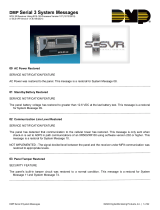
Accessing the Programmer
1. Momentarily place the Reset jumper over both
oftheJ16pinstoresetthepanel.
2. Enterthecode6653(PROG)andpress
COMMAND.
3. The keypad displays: PROGRAMMER.
Figure 1: XR100 Series Canadian Panel Showing Reset
To enable Wireless Keypad
Association operation:
Reset panel 3 times within
12 seconds.
To access the programmer:
Momentarily place the
Reset jumper over both of
the J16 pins to reset the
panel.
J16
Reset
AC
12345678 10 11 12 13 14 15 16 17 18 19
92
02122232425262728
+B BELL GND SMK GNDRED YEL GRN BLKZ1Z2Z3Z4Z5Z6Z7Z8 Z9+ Z9– Z10+ Z10–AC –B GND GND GNDGND
K6 K7
Output 1Output 2
J3
Phone Line
J10
J22
LX-Bus
Battery
Start
Power
LED
J8
PROG
J4
Tamper
Out1 Out2
Outputs 3-6
J11
3
4
5
6
J2
J1
Ethernet
OVC
Link LED
Activity LED
J23
R
L
X

Digital Monitoring Products XR100 Series Canadian Programming Guide
2
IntroductIon
1.3 Programmer Operation
Thereare18programmingsectionstochoosefrom:
Programming Item Section in This Manual Programming Item Section in This Manual
Initialization 2 Output Information 12
Communication 3 Output Groups 13
Network Options 4 Menu Display 14
Messaging Setup 5 Status List 15
Device Setup 6 PC Log Reports 16
Remote Options 7 Area Information 17
System Reports 8 Zone Information 18
System Options 9 Stop 19
Bell Options 10 Set Lockout Code 20
Output Options 11
To choose a section for programming, press any top row Select key when the keypad displays the name of
thatsection.Sections2through19containdetailedinstructionsforeachprogrammingstep.
1.4 Programmer Lockout Codes
The panel allows you to enter the programming function without entering a lockout code using steps 1 to 4
listedinGettingStarted.Werecommend,however,thatyouinstallaLockoutCodetorestrictprogramming
to only those persons your company authorizes. You can do this by using the SET LOCKOUT CODE feature in
theProgrammer.TheLockoutCoderestrictsanyunauthorizedpanelprogramming.
Afterresettingthepanelandenteringthecode6653,thekeypaddisplaysPROGRAMMER. Press COMMAND
to advance through the programming sections until SET LOCKOUT CODE displays(afterSTOP). Press any
top row Select key. The keypad displays ENTER CODE: –.Entera3to5digitProgrammerLockoutCode
and press COMMAND. The keypad displays ENTER AGAIN followed by ENTER CODE: –.Enterthesame3to5
digit code a second time and press COMMAND. The keypad displays CODE CHANGED.
Note:Thepanelwillnotaccepta5-digitLockoutCodehigherthan65535.
Before accessing programmer functions enter the new code number.
WritetheLockoutCodenumberdownandkeepitinasecureplacewithaccesslimitedtoauthorized
personsonly.LostLockoutCodesrequirethepaneltobesentbacktoDMPforrepair.Youmaycancela
LockoutCodebyentering00000attheSetLockoutCodecommand.
1.5 Reset Timeout
ThepanelhasafeaturethatrequiresyoutoentertheProgrammerwithin30minutesofresettingthe
panel.After30minutes,ifyouattempttoprogrambyenteringthe6653(PROG)code,thekeypaddisplays:
RESET PANEL. You must reset the panel and enter the program code then begin programming within the
next30minutes.
IfyouarealreadyintheProgrammeranddonotpressanykeysontheprogrammingkeypadfor30minutes,
the panel terminates programming. All data entered up to that time is Not saved unless you run the Stop
routine.
Note: Use the Stop routine to exit panel Programming. Ensure the keypad displays “SAVING PROGRAM”
to save all programming changes entered.
1.6 Power Up
When the XR100 Series Canadian panel is powered up after an AC power failure, any zone transitions are
notrecognizedfor60seconds.Normalzoneprocessingresumesattheendofthe60seconds.

XR100 Series Canadian Programming Guide Digital Monitoring Products
3
IntroductIon
1.7 Keypads
DMP offers multiple keypads in a variety of styles. All DMP keypads provide the same programming
capabilities.Eachkeypadanditsoperationareshownanddescribedinthefollowingsections.
1.8 Special Keys
Thefollowingspecialkeys/areasarecommontoallDMPkeypads.
COMMAND (CMD) Key
Pressing the COMMAND key allows you to go forward through the programming menu and through each
step of a programming sec tion. As you go through the programming, the keypad display shows any current
programming already stored in the panel memory. If no change is required for an option, press the
COMMAND key to advance to the next step.
The COMMAND key is also used to enter information into the panel’s memory such as phone numbers or
zone names. Press the COMMAND key after entering information.
Back Arrow (<—) Key
Use the Back Arrow key to back up one step while programming. The Back Arrow key is also used when
an error is made while entering in formation. Press the Back Arrow key once to erase the last character
entered.
Select Keys/Areas
ThetoprowofkeysarecalledtheSelectkeysonSecurityCommand,Thinline,andAqualitekeypads.Each
time you need to press a Select key, the keypad displays the function or options above one of the keys or in
the Select Area. Displaying choices above individual Select keys or in Select Areas allows them to be used
for many different applications. For example, you can enter AM or PM when programming the automatic
test time or answer YES or NO for a system option.
Duringprogramming,theSelectkeys/areasalsoallowyoutochangeinformationcurrentlyinpanelmemory
bypressingtheappropriateSelectkey/areaunderoronthedisplay.Youthenenterthenewinformation
using the keypad data entry digit keys.
When there are more than four re sponse options avail able, press the COMMAND key to display the next one
to four options. Pressing the Back Arrow key allows you to review the previous four choices.
TheSelectkeys/areasarealsousedforchoosingasectionfromtheprogrammingmenu.PressanySelect
key or touch the Select Area when the programming section name you want displays.
Note: On Wireless, Thinline and Aqualite keypads,wheninstructedtopresstherstSelectkey,pressthe
far left Select key; the second Select key is the second from the left; third Select key is second from the
right;andthefourthSelectkeyisthefarrightkey.SeeFigures5.
1.9 Entering Alpha Characters
Some options during programming require
you to enter alpha characters. To enter an
alpha character, press or touch the key that
has that letter written below it. The keypad
displays the number digit of the key. Next,
presstheSelectkey/areathatcorrespondsto
thelocationoftheletterunderthekey.PressingadifferentSelectkey/areachangestheletter.Whenan-
other digit key is pressed, the last letter displayed is retained and the process starts over.
Figure 5: Thinline/Aqualite/Wireless Select Keys
First Letter Second LetterThird Letter Special Char
acter
(CBA
Figure 3: Wireless Keypad
32-Character Display
Data Entry Digit keys
COMMAND Key
Back Arrow Key
Select Keys
Backlit Logo
and Proximity
Antenna
SMITH RESIDENCE
FRI 12: 51 PM
Figure 4: Thinline/Aqualite Keypad
32-Character Display
Armed LED
Power LED
Data Entry Digit keys
COMMAND Key
Back Arrow Key
Select Keys
JONES RESIDENCE
FRI 12:51 PM
Backlit Logo
and Proximity
Antenna

Digital Monitoring Products XR100 Series Canadian Programming Guide
4
IntroductIon
1.10 Entering Non-Alpha Characters
Toenteraspaceinanalphaentry,pressthe9digitkeyfollowedbythethirdSelectkey/area.Thethree
charactersonthe9digitkeyareY,Z,andspace.Youcanalsoenterthefollowingcharacters:–(dash),
.(period),*(asterisk),and#(poundsign)usingthe0(zero)keyandthefourSelectkeys/areasfromleft
toright.Forexample,toentera–(dash),pressthe0(zero)keyandthentheleftSelectkey/area.Adash
now appears in the keypad display. The table below shows the character locations for DMP keypads.
Key Number Select Key 1 Select Key 2 Select Key 3 Select Key 4
1 A B C (
2 D E F )
3 G H I !
4 J K L ?
5 M N O /
6 P QR &
7 S T U @
8 V W X ,
9 Y Z space _
0 - . * #
1.11 Keypad Displays Current Programming
Eachprogrammingoptiondisplayedatthekeypadshowsthecurrentlyselectedoptioninthepanel
memory. These options are either shown as a number, a blank, or a NO or YES. To change a number or
blank to a new number, press any top row Select key or touch any Select Area. The current option is
replacedwithadash.Pressthenumber(s)onthekeypadyouwanttoenterasthenewnumberforthat
option.Itisnotnecessarytoenternumberswithleadingzeros.Thepanelautomaticallyrightjustiesthe
number when you press the COMMAND key.
To change a programming option that requires a NO or YES response, press the Select key or touch the
SelectAreafortheresponsenotselected.SeeFigure12.
For example, if the current option is selected as YES and you want to change it to NO, on Security
Command, Thinline, or Aqualite keypads press the third top row Select key. The display changes to NO.
Press the COMMAND key to display the next option.
THEN
Press the black colored top
row Select key/area.
The keypad displays the new
selection. Press CMD to advance.
YESBELL TSTNOBELL TST
YESBELL TSTNOBELL TST
Thinline,
Aqualite,
Wireless
Keypads
Graphic
Keypads
Figure 6: Changing the Current Programming Option

XR100 Series Canadian Programming Guide Digital Monitoring Products
5
IntroductIon
1.12 Asterisks in Programming
Asterisks display next to a programming option that is already selected. As shown in the example, options
that are selected to display the current programming selection have an asterisk next to the number. Those
thatarenotselectedsimplydisplaythenumber.IntheDevicesexample,keypads3,6,and8arenot
selected.IntheAreasexample,areas3,6,and8arenotselected.Inbothexamplesthenumberswith
asterisks are selected.
Devices Areas
*1 *2 3 *4 *1 *2 3 *4
*5 6 *7 8 *5 6 *7 8
To select or deselect a number, simply enter the number using the digit keys on the keypad. This same
scheme is used when viewing the panel armed status and other programming and operational functions.
Remember to press the COMMAND key to display the rest of the device or area numbers.

Digital Monitoring Products XR100 Series Canadian Programming Guide
6
InItIalIzatIon
Initialization
NOTE: WHEN ANY PANEL PROGRAMMING IS CHANGED, THE STOP ROUTINE MUST BE RUN AND ‘SAVING
PROGRAM’ MUST DISPLAY ON THE KEYPAD IN ORDER TO SAVE THE PROGRAMMING CHANGES. SEE SECTION 17.1.
2.1
INITIALIZATION
Initialization
This function allows you to clear selected parts of the panel program back to the
factory defaults in preparation for system programming. Run the initialization
function on all new installations.
CODES? NO YES
SCHEDS? NO YES
Fo
r each section of the panel program you
can initialize, a NO or YES option is provided.
Selecting YES advances you to
a confirmation prompt.
If you select YES, the panel initializes that section of
the program and advances you to the next prompt.
If you select NO, the panel advances you to the next
section prompt but does not initialize that section of
the program.
SURE?YESNO
Selecting NO adv
ances
you to the next prompt.
2.2
INIT ALL? NO YES
SURE? YES NO
Clear All Memory
NO - LeavesexistingprogrammingintactthendisplaysClearAllCodes.
YES - ClearsallmemorythendisplaysResetPanel.ResetthepanelbyshortingJ16
andre-enterprogrammingmodetocontinue.
2.3
CODES? NO YES
SURE? YES NO
Clear All Codes
NO - Leavesexistingcodesintact.
YES - Clearstheusercodeanduserprolememoryandassignsusercodenumber
99tothehighestuserposition.
Note: The user name for the default user code is created using the current
programmed primary user language.
2.4
SCHEDS? NO YES
SURE? YES NO
Clear All Schedules
NO - Leavesexistingschedulesintact.
YES - Clears all shift, and output schedules.
2.5
EVENTS? NO YES
SURE? YES NO
Clear Display Events Memory
NO - Leavesexistingeventmemoryintact.
YES - Clears the events memory.
2.6
ZONES? NO YES
SURE? YES NO
Clear Zone Information
NO - Leavesexistingzoneinformationintact.
YES - Clearsthezoneinformationforallzones.Allzonesaremarked*UNUSED*
and must be renamed before being able to display on any system keypad.
2.7
AREAS? NO YES
SURE? YES NO
Clear Area Information
NO - Leavesexistingareainformationintact.
YES - Clearstheareainformationforallareas.Allareasaremarked*UNUSED*and
must be renamed before being able to display on any system keypad.
2.8
OUTPUTS? NO YES
SURE? YES NO
Clear Output Information
NO - Leavesexistingoutputinformationintact.
YES - Clears all programmed Output names and any output cutoff assignment.

XR100 Series Canadian Programming Guide Digital Monitoring Products
7
InItIalIzatIon
2.9
COM/RMT? NO YES
SURE? YES NO
Clear Communication and Remote Options
NO - Leavesexistingcommunicationandremoteoptionsintact.
YES - Clears communication and remote options programming to factory defaults.
2.10
DEFAULTS NO YES
SURE? YES NO
Set to Factory Defaults
NO - Leavesexistingpanelprogrammingintact.
YES - Sets the remainder of the panel programming back to the factory defaults.
Note:SetstheProgrammingandUserlanguagetoEnglish.

Digital Monitoring Products XR100 Series Canadian Programming Guide
8
CommuniCation
Communication
3.1
COMMUNICATION
Communication
Congurethecommunicationoptionsforthepanel.Theinformationyouprogram
varies with the Communication Type you select.
3.2
ACCOUNT NO: 12345
Account Number
TheAccountNumberisa1to5digitnumberusedtoidentifywhichpanelissending
amessage.EntertheaccountnumbersenttotheSCS-1RReceiver.Messagesmay
besenttoacentralstationorviaPCLogReportstoaPC.Thedefaultis12345.
NET, CELL, and DD -Therangeofvalidaccountnumbersforapanelis1to65535.
For accounts of four digits or less, do not enter leading zeros.
CID - Chooseanaccountnumberbetween1and9999.
3.3
XMIT DELAY: 30
Transmit Delay
Enterthenumberofseconds(15to45)thepanelwaitsbeforesendingburglary
zones(Night,Day,orExit)reportstothereceiver.Otherzonetypereportsare
sent immediately. Alarm bells and relay outputs are not delayed during this period.
ProgramBurglaryOutputsforpulsedorsteady,andsetAbortReportstoYESif
OpeningandClosingreportsarenotbeingsent.Enter0(zero)todisablethis
function.Thedefaultis30.
If the area where the alarm occurred is disarmed during the Transmit Delay time,
onlyanAbortReport(S45)messageissenttothereceiver.Iftheareawhere
the alarm occurred is disarmed after the alarm message is sent to the receiver
but before the Bell Cutoff time expires even if the alarm was silenced, an Alarm
Cancelled(S49)messageissent.Otherwisethealarmissentattheendofthe
delay. The Alarm Cancelled report cannot be disabled.
Note: For Commercial Burglary Installations, the combined Transmit Delay
(Abort Window) and Entry Delay must not exceed one (1) minute.
3.4
PATH: -
Communication Path
Uptoeightcommunicationpathsmaybeprogrammed.Eachpathisdesignatedas
a primary or backup communication route. Path 1 is always Primary but other paths
may be programmed as additional primary or backup.
Eachprimarypathestablishesanewpathgroup.Apathgroupismadeupofthe
primary path and its subsequent backup paths. Typical communication takes place
on the primary path with backup paths being used only when the primary path fails
or when the backup path is programmed to duplicate messages. There is no option
tobackuppath8.
3.5
COMM TYPE: DD
Communication Type
Speciesthecommunicationmethodthepanelusesonthispathtoreportsystem
eventstoDMPSCS-1R,SCS-VRReceiversornon-DMPreceivers.DefaultisDDfor
Path1,andNONEforPath2-8.
NONE - Forlocalsystems.SelectingNONEendscommunicationprogramming.
DD - DigitalDialercommunicationstoaDMPSCS-1RReceiver.
NET - Network communication using the panel onboard network connection. The
DMPNetwork/Outputreportingformatistransmittedoveradatanetworktothe
SCS-1RReceiver.
CID - Thisoptionallowsthepaneltocommunicatetonon-DMPreceiversusingthe
Contact ID format.
CELL - This option allows communication over the cellular network using digital
cellulartechnologywiththe464-263HDigitalCellularCommunicators.
NONE DD NET CID

XR100 Series Canadian Programming Guide Digital Monitoring Products
9
CommuniCation
3.6
PATH TYPE: BACKUP
Path Type
ThePathTypedenesifthepathisPrimaryorBackup.BecausePath1isPrimary,
thisoptiononlydisplaysforpaths2-8.DefaultisBackup.
Note:IfthePrimaryCommunicationTypeisCELL,thenthebackupCommunication
TypecanonlybeNET.
3.7
TEST RPT: YES
Test Report
Test Report determines if test reports are sent on this path. Reports are sent
according to the programming in Test Frequency and Test Time. Default is Yes.
SelectYEStoallowtheprogrammedtestreporttobesentonthepathcurrently
being programmed.
SelectDEFERtonotsendatestreportifthepanelcommunicatesanymessage
to the receiver within the time set in Test Frequency. Select NO to not send test
reports on this path.
3.8
TEST FREQ: 1 DY
Test Frequency
TestFrequencydeterminesthefrequencyofthetestreport.Enteranumberfrom1
to60andselectDY(Day)orHR(Hour)bypressingthefarrighttoprowselectkey.
Default is 1 Day.
3.9
TEST DAY: SUN
Test Day
Use this option to set the day of the Test Report. This option appears only when Test
Report is Yes, Test Frequency is Day and a multiple of seven. Press the COMMAND key
todisplaytherstfourdaysoftheweek.PresstheCOMMANDkeytodisplaythelast
three days. Select the day of the week to send the test report. Default is Sunday.
3.10
TEST TIME:
0:00 AM
Test Time
Use this option to select the time of day for Test Reports. Select the hour, minute
andAM/PM.Enter0:00AMtodisablethisfeature.Defaultis0:00AM.
3.11
CHECKIN: NO YES
Check In
ThisoptiondisplaysiftheCOMMTYPEisNET,orCELL.Check-inreportsarea
methodofsupervisingthepanelforcommunicationwiththereceiver.ForNETthe
defaultisYES.ForCELL,thedefaultisNO.
CHECKIN:
NO YES RND ADPT
SelectRND(Random)forthepaneltocheck-inatrandomtimesfrom6to60minutes
whenallareasaredisarmed.Ifanyareaisarmedacheck-inissentevery6minutes.
SelectADPT(Adaptive)forabackuppathtoadapttothecheck-inprogramming
fromthisgroupsprimarypathiftheprimarypathbecomesunavailable.Check-in
programmingincludesCheck-inandFailTime.
CHECKIN:
ADP3
SelectADP3(Adaptive3)forabackuppathtoadaptusinga3minuteCheck-inand
Fail Time if the primary path becomes unavailable. This option also indicates a
CommunicationTrouble(S10)ifthecelltowerisunavailablefor3minutes.
CHECKIN MINS: 200
WhenYESisselected,enterthenumberofminutesbetweencheck-inreports,from
2to240forNETor3to240forCELL,whenthepanelisarmedordisarmed.For
CELL,thedefaultis0.ForNETthedefaultis200.
3.12
FAIL TIME: 240
Fail Time
ThisoptiondisplaysifCHECKINissettoYES.EnteringaFAILTIMEallowsthe
receivertomissmultiplecheck-insbeforeloggingthatthepanelismissing.The
maximumfailtimeis240minutes.Forexample,ifCHECKINis10andFAILTIMEis
30,thereceiveronlyindicatesaPanelNotRespondingafter30minutes.TheFAIL
TIMEmustbeequaltoorgreaterthantheCHECKINtime.Defaultis0forCELL.
Defaultis240forNET.
3.13
RECEIVER IP
Receiver IP
ThisoptiondisplaysonlyiftheCommunicationTypeisNETorCELL.Enterthe
Receiver IP address where the panel sends network messages. The Receiver IP
Addressmustbeuniqueandcannotbeduplicatedonthenetwork.Enterall12
digitsandleaveouttheperiods.Forexample,enterIPaddress192.168.0.250as
192168000250.Theperiodsdisplayautomatically.
NO YES DEFER
PRIMARY BACKUP

Digital Monitoring Products XR100 Series Canadian Programming Guide
10
CommuniCation
3.14
RECEIVER PORT -
Receiver Port
2001
Enterthereceiverportnumber.Validrangeis1to65,535.Defaultis2001.
3.15
FIRST PHONE NO.
First Telephone Number
This option displays only if the Communication Type is DD or CID.
Thisistherstnumberthepaneldialswhensendingreportstothereceiver.Phone
numberscanhavetwolinesof16characterseachtoequalupto32characters.
EnterPtoprogramathree-secondpauseinthedialingsequence.ThePcharacter
countsaspartofthe32allowablecharacters.
EnterRastherstcharacterforrotary(pulse)phonefunction.TheRcharacter
countsaspartofthe32allowablecharacters.
Call Waiting: You can place the “*70P”(Star,Seven,Zero,Pause)inthe
telephonenumberrstpositiontocancelCallWaiting.Forexample,programNET
withsecondlineDDandphonenumber*70P555-1212,andyouhaveNETwithCall
Waiting cancelled on the second line.
Caution:Acallwaitingcancelprogrammedonanon-callwaitingtelephoneline
would prevent communication to the central station.
3.16
SECOND PHONE NO.
Second Telephone Number
Thepaneldialsthesecondnumberwhentwosuccessivetriesusingtherstnumber
fail. If the panel cannot reach the receiver after two attempts using the second
number,itreturnstotherstnumberandmakestwoadditionalattempts.Atotal
oftendialingattemptsaremadeusingtherstandsecondphonenumbers.
Eachnumbercanbeupto32charactersinlengthincludinganyPorRcharacters
entered for pause or rotary connections or call waiting cancel option.
Should all ten attempts fail, the panel continues to attempt sending the message
using the next programmed path. If all programmed communication paths fail, the
panel clears the communication buffer and makes one communication attempt
eachhourtosendaTRANSMITFAILED(S87)reporttothereceiver.AccesstheUser
MenuDisplayEventsfeaturetoviewthereportinformationnotsenttothereceiver
ordownloadthereportwithDMPRemoteLink™software.
3.17
ADVANCED? NO YES
Advanced Programming
Select Yes to enter the Advanced Programming menu for the communication path
currently being programmed.
3.18 First GPRS APN
EntertherstAPN(AccessPointName).Thisallowsanaccesspointforcellular
communication and is used to connect to a DNS network. The APN may contain two
linesof16characterstoequal32characters.DefaultissettoNMRX.CA.APN.
Second GPRS APN
EnterthesecondAPN(AccessPointName).Thisworksasabackupincasetherst
APNfails.TheAPNmaycontaintwolinesof16characterstoequal32character
DefaultissettoINTERNET.COM.
3.19
FAIL TEST HRS: 0
Fail Test Hours
This option sets the frequency for a Backup or Adaptive path to send a test report
when the closest previous path fails within its path group.
For example, if a backup path is programmed to send a weekly test report and the
FailTestFrequencyissetto2hours,whenthepreviouspathfailswithinitsgroup,
thebackuppathstartssendingatestevery2hoursuntilthepreviouspathrestores.
If Fail Test Frequency is set to 0, test reports are sent only according to Test Report
programming.Rangeis0to24hours.Defaultis0.
NMRX.CA.APN
-
FIRST GPRS APN
INTERNET.COM
-
SECOND GPRS APN

XR100 Series Canadian Programming Guide Digital Monitoring Products
11
CommuniCation
3.20
PROTOCOL: TCP
Protocol
ThisoptiondisplaysonlywhenCommunicationTypeisNET.
Select TCP to communicate over the network using TCP protocol. Select UDP to
communicate using UDP protocol. Default is TCP.
3.21
RETRY SECONDS: 6
Retry Seconds
ThisoptiondisplaysforNETCommunicationTypes.
Enterthenumberofseconds(between6and15)thepanelshouldwaitbefore
retrying to send a message to the receiver if an acknowledgment was not received.
The panel retries as many times as possible for a period of one minute before
sendinganetworktroublemessage.Forexample,ifretrytimeissetto15,the
panelretriesfourtimes.ThedefaultRetryTimeis6seconds.
Note:IfTCPisenabled,theminimumRetryTimeprogrammedis6seconds.
3.22
SUB CODE NO
Substitution Code
ThisoptiondisplayswhentheCommunicationTypeisNET,orCELL.ThePanel
Substitution Code increases the level of security by helping to ensure that the
panel sending the message to the receiver has not been substituted by another
panel. The default is NO.
SelectYEStosendasubstitutioncodewitheverymessage.
SelectSHARED(SHR)tousethesamesubstitutioncodeasoperatingintheprevious
path.
3.23
893A: NO YES
893A
This option displays when the Communication Type is DD or CID.
The893AoptionallowsreportstobesenttothereceiveronasecondDDlineusing
the893Amodule.DefaultisNo.
Whenusingthisoption,TestReportmessages(S07AutomaticRecallTestorS88
Unrestored System Recall Test) will be sent to the receiver at the frequency
programmedinTestFrequency,alternatingbetweentherstandsecondphone
line.
Forexample,aDDpathwithan893Amodulesetfordailytestreportfrequency
willsendatestreportthroughphoneline1onedayandphoneline2thenextday.
If893AoptionissettoYES,enteruptoa3digitprextobedialedbeforethe
secondphonenumber.Ifnoprexisentered,thesecondphonenumberisdialedas
originally entered.
3.24
ALARM SWITCH: 1
Alarm Switch
This option displays for DD or CID Communication Types.
Enterthenumberofattemptstosendanalarmmessagebeforeswitchingto
thenextpath.Rangeisfrom1to10.Allnon-alarmmessageswillbesentfor
10 attempts on the dialer before a switch is initiated. If the path immediately
following this channel is not a backup path, this option has no effect. Default is 1.
3.25
DUPLICATE ALARMS
Duplicate Alarms
This option displays for BACKUP paths. If Yes is selected, the current backup path
duplicates all alarms occurring on its group primary path. Default is No.
3.26
ALARM YES
Alarm Reports
This option displays when the Path Type is Primary. All backup paths within the
group follow the same programming for Alarm Reports. Default is Yes.
NO YES FIRE
WhenYESisselected,thefollowingreportsaresenttothereceiverforallzone
types:
•Alarm •Bypass •Reset •Restore
WhenFIREisselected,thefollowingreportsaresentforFire,FireVerifyand
SupervisoryZones:
•Alarm •Bypass •Reset •Restore
NO YES SHARED
NO YES
-
2ND LINE PREFIX:

Digital Monitoring Products XR100 Series Canadian Programming Guide
12
CommuniCation
3.27
SPV/TRBL YES
Supervisory/Trouble Reports
This option displays when the Path Type is Primary. All backup paths within the
groupfollowthesameprogrammingforSupervisory/TroubleReports.DefaultisYes.
NO YES FIRE
WhenYESisselected,thefollowingreportsaresentforallzonetypes:
•Trouble •LowBattery •Missing •Fault
•Restorals •SystemTroubles •SystemRestoral
WhenFIREisselected,thefollowingreportsaresentforFire,FireVerify,and
SupervisoryZones:
•Trouble •LowBattery •Missing •Fault
•Restorals •SystemTroubles •SystemRestoral
ServicemanreportsaresentregardlessoftheselectionmadeforSupervisory/
Trouble reports.
3.28
O/C USER NO YES
Opening/Closing and User Reports
This option displays when the Path Type is Primary. All backup paths within the
groupfollowthesameprogrammingforOpening/ClosingandUserReports.Default
is Yes.
WhenYESisselected,thefollowingreportsbyuseraresenttothisreceiver.
•Opening •Codechanges(includingadding,deleting,changing)
•Closing •Schedulechanges(temporary,permanent,shift)
•Bypass •Holidaydatechanges
•Reset
3.29
DOOR ACS YES
Door Access Report
This option displays when the Path Type is Primary. All backup paths within the
group follow the same programming for Door Access Reports. Default is Deny.
NO YES DENY
SelectYEStoenableDoorAccessGrantedandDeniedreportstothisreceiver
wheneveradooraccessisgrantedtoauser.TheDoorAccessGrantedreportis
only sent if the keypad number has also been selected in Access Keypads under the
SYSTEM REPORTS programming.
SelectDENYtoenableDoorAccessDeniedreportsonlytothisreceiverwhenadoor
access is denied to a user.
3.30
SEND COMM TRBL:
Send Communication Trouble
NO YES
This option displays for each path and determines if and how communication
trouble on the path is sent to the receiver. A trouble message indicates both the
path number and communication type that failed. Default is Yes.
3.31
SEND PATH INFO:
Send Path Information
NO YES
ThisoptiondisplaysforeachpathandifYES,eachpanelmessageincludespath
information such as path number, communication type, and path type. Default is
No.
/