Page is loading ...

1
IMPORTANT:
Go to www.extron.com for the complete
user guide, installation instructions, and
specifications before connecting the
product to the power source.
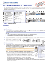
XTP T FB 202 4K • Setup Guide
This guide provides instructions for an experienced installer to install
and connect the Extron XTP T FB 202 4K into an Ackermann GB3
(OBO-Betterman), MK Electric CableLink Plus Modular, MK Electric
CableLink Plus Single Pan, ElectraPlan, or PUK oor box.
Side Panel
1.0 A MAX
LINK
XTP OUT
SIG
G
REMOTE
RS-232
Rx
Tx
POWER
12V
1.0A MAX
−+
A
C
D
E
H
Figure 1. XTP T FB 202 4K Side and Top Panels
Input and Power Connections Throughput and Control Connections Control Connections and LEDs
A
DC power connector
B
Analog audio input connector
C
HDMI input connector
D
Analog 15-pin HD VGA connector
E
XTP output connector and LED indicators
F
RS-232/IR Over XTP connector
G
LAN connector
H
Remote RS-232 connector
I
USB conguration connector
J
Reset button
K
LED indicators
Installation
Planning
CAUTION: Risk of personal injury. Failure to check these items may result in personal injury.
ATTENTION: Failure to check the items listed below may result in property damage.
Check that the installation meets the building, electrical, and safety codes.
Mounting and Cabling
Step 1 — Preparing the floor box
a. Install the oor box as directed by the manufacturer.
NOTE: Run all required cables and secure them with cable clamps.
b. Turn off or disconnect all equipment power sources.
Step 2 — Installing adapters
a. Determine a position in the oor box to mount the XTP T FB 202 4K (see the image to the
right).
b. Identify the applicable adapter plates for the oor box (see the table below).
c. Install adapter plates to the same pair of mounting slots (see the table below for slot
recommendations) for the same position in the floor box. Slide the top ange into the
mounting slot and rotate the adapter plate down so the bottom ange rests against the
wall of the oor box.
Floor Box Adapter Plates Positions Highest
Mounting Slot
Additional Notes
Ackermann GB3
(OBO Betterman)
995241 (2)
995241 (2) and 995242 (1)
1 and 3
2
3rd from top For position 2, use the provided screws to attach
the 995242 adapter plate to either 995241 adapter
plate.
MK Electric CableLink Plus
Single Pan
995243 (2) 1 and 3 N/A Do not use position 2. Use mounting screws to
secure the adapter plates to the oor box (see
gure 4).
MK Electric CableLink Plus Modular 995244 (2) 1, 2, and 3 3rd from top
ElectraPlan 995300 (2) 1, 2, and 3 3rd from top
PUK 995300 (2) 1, 2, and 3 3rd from top
CONFIG
LAN
PWR
G
REMOTE IR
Rx
Tx
Tx
Rx
HDMI IN
VGA IN
XTP T FB 202 4K
HDMI
VGA
HDCP
AUTO
CLIP
AUDIO IN
OVER XTP
RESET
Top Panel
BF
G
I
J
K
OBO Bettermann
GESR7 Floorbox Assembly
1
2
3

2
XTP T FB 202 4K • Setup Guide (Continued)
Step 3 — Connecting side panel connectors under the adapters
a. Connect a twisted pair cable between the XTP connector (see
E
above) of the XTP T FB 202 4K to an XTP receiver or XTP matrix switcher
(see Twisted Pair Recommendations for XTP Communication on page 4).
ATTENTION: Do not connect this connector to a computer data or telecommunications network.
Signal LED indicator — Lights when the device is transmitting a video signal or a test pattern.
Link LED indicator — Lights when a valid link between an XTP input and output is established.
b. For serial RS-232 control, connect a host device or control system to the 3.5 mm, 3-pole captive screw connector (see
H
on page 1). Wire
the connector as show in gure 2.
Do not tin the wires!
Controlling
Device
Transmit (Tx)
Receive (Rx)
Ground (G)
Transmit (Tx)
Receive (Rx)
Ground (G)
Bidirectional
G Rx Tx
REMOTE
RS-232
Figure 2. Remote RS-232 Wiring
c. Power the XTP T FB 202 4K in one of the following methods:
• Connect the provided external power supply to the 2-pole captive screw connector for local 12 V power (see
A
on page 1).
• Connect an XTP Power Injector to the XTP connection between the XTP T FB 202 4K and a locally powered XTP receiver or XTP matrix
switcher.
• Connect the XTP T FB 202 4K to an XTP matrix switcher and enable the remote power feature on the XTP matrix switcher.
Step 4 — Mounting
a. Place the XTP T FB 202 4K in the desired position in the oor box so that the side panel connectors face towards the opening of the oor
box.
ATTENTION: Ensure there is enough space between the top panel connectors and the lid of the oor box so the lid fully closes.
b. Using the provided self-threading screws, secure the XTP T FB 202 4K to the adapter plates (see gures 3 through 6).
Ackermann GB3 (OBO Betterman) floor box
POWER
XTP T FB 202 4K
VGA IN
HDMI IN
HDMI
VGA
HDCP
AUTO
CLIP
AUDIO IN
LAN
REMOTE
RS-232
-
+
G
Rx
Tx
12V
1.0 A MAX
CONFIG
RESET
Tx
Rx
G
Tx
Rx
OVER XTP
RS-232
IR
XTP OUT
POWER
XTP T FB 202 4K
VGA IN
HDMI IN
HDMI
VGA
HDCP
AUTO
CLIP
AUDIO IN
LAN
REMOTE
RS-232
- +
G
Rx
Tx
12V
A MAX
CONFIG
RESET
Tx
Rx
G
Tx
Rx
OVER XTP
RS-232
IR
XTP OUT
Extron
XTP T FB 202 4K
(shown in OBO Bettermann
GESR7 floorbox assembly)
995242
995241
Figure 3. XTP T FB 202 4K in an Ackermann GB3 (OBO Betterman) Floor Box
ATTENTION: For position 2, install adapter plate 995242 to one of the other adapter plates.

3
MK Electric CableLink Plus Single Pan floor box
POWER
XTP T FB 202 4K
VGA IN
HDMI IN
PWR
HDMI
VGA
HDCP
AUTO
CLIP
AUDIO IN
LAN
REMOTE
RS-232
-
+
G
Rx
Tx
12V
1.0 A MAX
CONFI
G
RESET
Tx
Rx
G
Tx
R
x
OV
ER XTP
RS-232
IR
XTP OUT
POWER
XTP T FB 202 4K
VGA IN
HDMI IN
P
WR
HDMI
VGA
HDCP
AUTO
CLIP
AUDIO
IN
LA
N
REMOTE
RS-232
-
+
G
Rx
Tx
12V
A M
AX
CONFIG
RE
SET
Tx
Rx
G
Tx
Rx
OVER XTP
RS-232
IR
XT
POW
E
R
XTP
T FB 202
VGA
IN
HDMI
IN
PWR
HDMI
VGA
HDCP
AUTO
CLIP
AUDI
O IN
LAN
R
E
MOTE
R
S-23
2
12V
A M
AX
C
ON
F
IG
R
ESE
T
T
x
R
x
G
T
x
R
x
OVER XTP
RS
-
232
I
R
Extron
XTP T FB 202 4K
(shown in Cablelink Single
Pan floorbox assembly)
995243
995243
Do not use
this position
Figure 4. XTP T FB 202 4K in an MK Electric CableLink Plus Single Pan Floor Box
MK Electric CableLink Plus Modular floor box
POWER
XTP T FB 202 4K
VGA IN
HDMI IN
PWR
HDMI
VGA
HDCP
AUTO
CLIP
AUDIO IN
LAN
REMOTE
RS-232
-
+
G
Rx
Tx
12V
1.0 A MAX
CON
FIG
R
ESET
Tx
Rx
G
Tx
Rx
OVER XTP
RS-232
IR
XTP OUT
P
OWER
XTP T FB 202 4K
VGA IN
HDMI IN
PWR
HDMI
VGA
HDCP
AUTO
CLIP
AUDIO IN
LAN
REMOTE
R
S-232
-
+
G
Rx
T
x
12V
A MAX
CONFIG
RESET
Tx
Rx
G
Tx
Rx
OV
ER XTP
RS-232
IR
XT
P OU
T
Extron
XTP T FB 202 4K
(shown in Cablelink Plus
modular floorbox assembly)
995244
995244
Figure 5. XTP T FB 202 4K in an MK Electric CableLink Plus Modular Floor Box
ElectraPlan or PUK floor box
POWER
XTP T FB 202 4K
VGA IN
HDMI IN
PWR
HDMI
VGA
HDCP
AUTO
CLIP
AUDIO IN
LAN
REMOTE
RS-232
-
+
G
Rx
Tx
12V
1.0 A MAX
CONFIG
RESET
T
x
Rx
G
Tx
Rx
OVER XTP
RS-232
IR
XTP OUT
POWER
XTP T FB 202 4K
VGA IN
HDMI IN
PWR
HDMI
VGA
HDCP
AUTO
CLIP
AUDIO IN
LA
N
REMOTE
RS-232
-
+
G
Rx
Tx
12V
A MAX
CONF
IG
RESET
Tx
Rx
G
Tx
Rx
OVER XTP
RS-232
IR
XTP OUT
Extron
XTP T FB 202 4K
(shown in Electraplan
floorbox assembly)
995300
995300
Figure 6. XTP T FB 202 4K in an ElectraPlan (or PUK) Floor Box

4
68-2832-50 Rev. A
04 19
Step 5 — Connecting Inputs
a. Connect an unbalanced analog audio input source to the 3.5 mm TRS jack. Both video inputs can share this audio input. HDMI embedded
audio is normally given priority (see
B
on page 1).
b. Connect an analog RGB video source to the female 15-pin HD VGA connector (see
D
on page 1).
c. Connect a digital video source to the female HDMI connector (see
C
on page 1). It can accept HDMI, DVI (with an appropriate adapter), or
DisplayPort video signals.
NOTE: Video input from a DisplayPort source must be a dual-mode DisplayPort source.
Step 6 — Connecting Throughput Devices
a. To pass bidirectional serial command signals between XTP-compatible devices, connect a control
device to the three leftmost poles (Tx, Rx, and G) of the 5-pole captive screw connector (see
F
on
page 1). To transmit and receive IR signals, connect a control device to the three right most poles
(G, Tx, and Rx).
NOTE: RS-232 and IR data can be transmitted simultaneously and share the ground pole (G).
b. Connect a host device or control LAN or WAN to the LAN RJ-45 connector for pass-through 10/100Base-T Ethernet communication
(see
G
on page 1). This is an Ethernet pass-through port with LEDs to indicate link and activity status.
Step 7 — Connecting a Control Device
Connect a host device, such as a computer, to the female mini-USB B port to congure the device or update rmware (see
I
on page 1).
Twisted Pair Recommendations for XTP Communication
The XTP T FB 202 4K is compatible with CAT 5e, 6, 6a, and 7 shielded twisted pair (F/UTP, SF/UTP, and S/FTP) and unshielded twisted pair
(U/UTP) cable. Extron recommends using the following practices to achieve full transmission distances up to 330 feet (100m) and reduce
transmission errors.
• Use Extron XTP DTP 24 SF/UTP cable for the best performance. If not using XTP DTP 24 cable, at a minimum, Extron recommends
24 AWG, solid conductor, STP cable with a minimum bandwidth of 400 MHz.
• Terminate cables with shielded connectors to the TIA/EIA-T568B standard.
• Limit the use of more than two pass-through points, which may include patch points, punch down
connectors, couplers, and power injectors. If these pass-through points are required, use CAT 6 or
6a shielded couplers and punch down connectors.
NOTE: When using CAT 5e or CAT 6 cable in bundles or conduits, consider the following:
• Do not exceed 40% ll capacity in conduits.
• Do not comb the cable for the rst 20 m, where cables are straightened, aligned, and
secured in tight bundles.
• Loosely place cables and limit the use of tie wraps or hook and loop fasteners.
• Separate twisted pair cables from AC power cables.
Operation
After all connected devices are connected and powered on, the system is fully operational. The XTP T FB 202 4K can be congured and
controlled through the Extron XTP System Conguration Software or SIS
™
commands (see the XTP T FB 202 4K User Guide available on the
Extron website, www.extron.com).
Indicators
Power LED indicator — Lights when power is applied.
HDMI LED indicator — Lights when the HDMI input signal is detected.
VGA LED indicator — Lights when the VGA input signal is detected.
HDCP LED indicator — Lights when the HDMI input signal is encrypted.
Auto switch LED indicator — Lights when device is in auto switch mode.
Audio Clipping LED indicator — Lights when the analog audio input signal remains above -3 dBFS. It remains lit for 200 ms after the signal falls
below -3 dBFS.
TIA/EIA-T568B
Pin Wire Color
1 White-orange
2 Orange
3 White-green
4 Blue
5 White-blue
6 Green
7 White-brown
8 Brown
12345678
RJ-45
Connector
Insert Twisted
Pair Wires
Pins:
Pin
1
2
3
4
5
6
7
8
Wire color
White-green
Green
White-orange
Blue
White-blue
Orange
White-brown
Brown
Wire color
T568A T568B
White-orange
Orange
White-green
Blue
White-blue
Green
White-brown
Brown
Tx/Rx
Pins
RxTx
RS-232
RxTx
TxRx
RxTx
IR Device
RS-232 De
vice
G
G
G
IR
© 2019 Extron Electronics — All rights reserved. www.extron.com
All trademarks mentioned are the property of their respective owners.
Worldwide Headquarters: Extron USA West, 1025 E. Ball Road, Anaheim, CA 92805, 800.633.9876
For information on safety guidelines, regulatory compliances, EMI/EMF compatibility, accessibility, and related topics, see the
Extron Safety and Regulatory Compliance Guide on the Extron website.
/