IMPORTANT:
Refer to www.extron.com for the complete
user guide, installation instructions, and
specifications before connecting the
product to the power source.
IMPORTANT:
Refer to www.extron.com for the complete
user guide, installation instructions, and
specifications before connecting the
product to the power source.
XTP T VGA • Setup Guide
This guide provides instructions for an
experienced installer to install and connect
the Extron XTP T VGA transmitter. For
complete instructions, see the XTP T VGA
User Guide at www.extron.com.
POWER
12V
1.0 A MAX
Rx GTx
RS-232
IR
RxTx
AUDIO
LOOP-THRU
UNIVERSAL
XTP T VGA
LAN
SIG LINK
XTP OUT
RESET
INPUTS
OVER XTP
AB CDEFGH
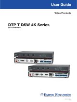
Power and Input Connections Throughput Connections and Reset Button
A
DC power connector and LED indicator
B
Universal analog 15-pin HD connector
C
Analog 15-pin HD loop-through connector
D
Analog audio input connector
E
RS-232/IR Over XTP connector
F
XTP output connector
G
LAN connector
H
Reset button
Figure 1. Rear Panel Features
Installation
Step 1 — Mounting
Turn off or disconnect all equipment power sources
and mount the switcher as required (see the
XTP T VGA User Guide on the Extron website,
www.extron.com, for mounting considerations)
Step 2 — Connecting inputs
a. Connect an analog RGB video source or (with an appropriate adapter) a YUV, S-video, or composite video source to the female 15-pin HD
connector (see gure 1,
B
).
The 15-pin HD Connector Pinout for RGB Video table above shows the pinout conguration for RGB video. For component video, use the
R (R-Y) and R return pins (pins 1 and 6), G (Y) and G return pins (pins 2 and 7), and B (B-Y) and B return pins (pins 3 and 8). For S-video, use
the B, B return (C-chroma), G, and G return (Y-luma) pins. For composite video, use the G pin and the associated return pin. Input only sync
signals, no video signals, on the sync pins, 13 and 14.
b. Connect an analog RGB, YUV, S-video, or composite video display to the female 15-pin HD VGA connector for local loop-through display of
the input source (see gure 1,
C
).
c. Connect an unbalanced analog audio input source to the 3.5 mm TRS jack (see gure 1,
D
).
Step 3 — Connecting Throughput Devices
a. Connect a twisted pair cable between the XTP connector of the XTP T VGA and an XTP receiver (see gure 1,
F
).
ATTENTION: Do no connect this connector to a computer data or
telecommunications network.
The XTP T VGA is compatible with shielded twisted pair (F/UTP, SF/UTP, and S/FTP) cables.
Extron recommends using the following practices to achieve full transmission distances up to
330 feet (100 meters) and reduce transmission errors.
• Use Extron XTP DTP 24 SF/UTP cable for the best performance. If not using
XTP DTP 24 cable, at a minimum, Extron recommends 24 AWG, solid conductor, STP
cable with a minimum bandwidth of 400 MHz.
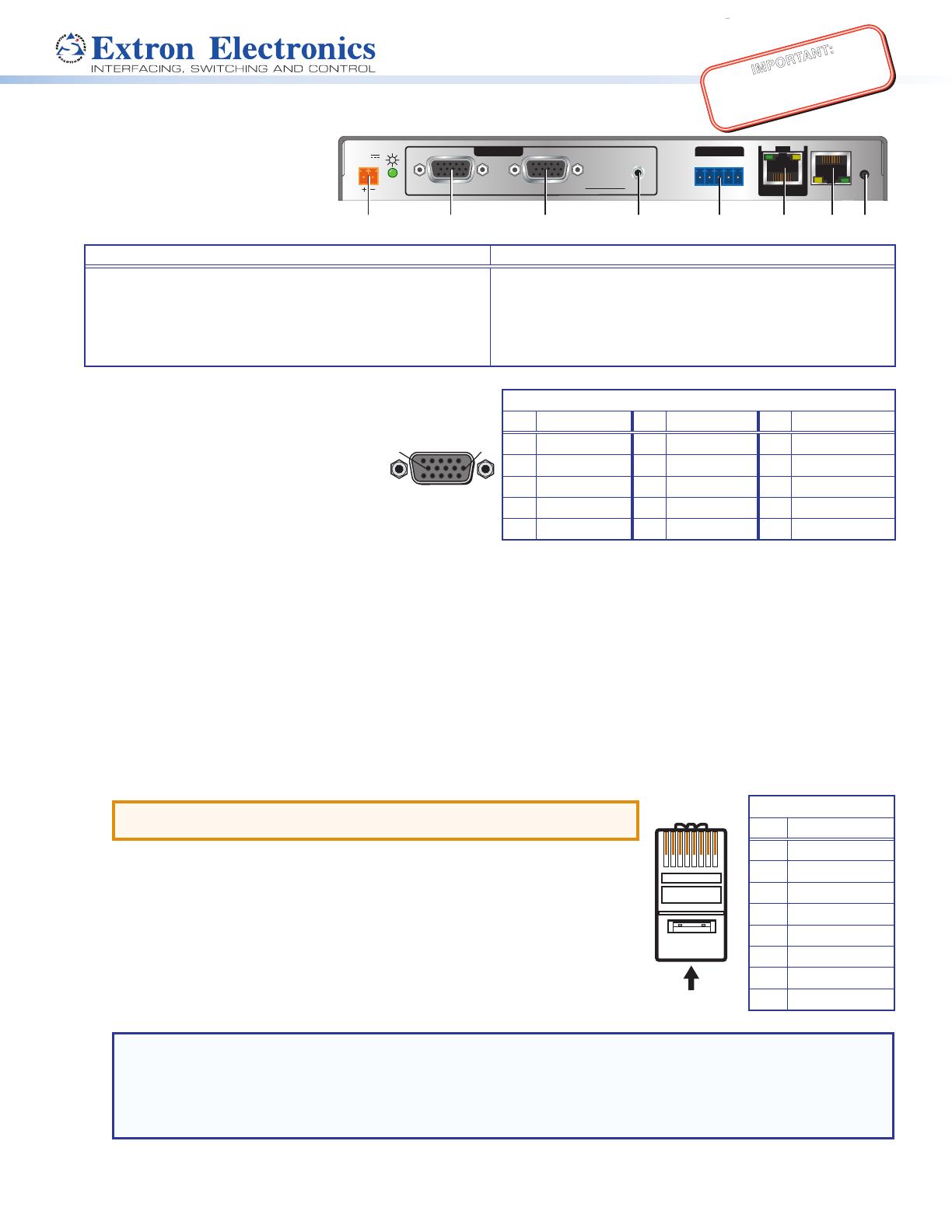
• Terminate cables with shielded connectors to the TIA/EIA-T568B standard.
• Limit the use of more than two pass-through points, which may include patch points,
punch down connectors, couplers, and power injectors. If these pass-through points are
required, use shielded couplers and punch down connectors.
NOTE: When using shielded twisted pair cable in bundles or conduits, consider the following:
• Do not exceed 40% ll capacity in conduits.
• Do not comb the cable for the rst 20 m, where cables are straightened, aligned, and secured in tight bundles.
• Loosely place cables and limit the use of tie wraps or hook-and-loop fasteners.
• Separate twisted pair cables from AC power cables.
Signal LED — Lights when the device is transmitting a video signal or a test pattern.
Link LED — Lights when a valid link between an XTP input and output is established.
TIA/EIA-T568B
Pin Wire Color
1 White-orange
2 Orange
3 White-green
4 Blue
5 White-blue
6 Green
7 White-brown
8 Brown
12345678
RJ-45
Connector
Insert Twisted
Pair Wires
Pins:
Pin
1
2
3
4
5
6
7
8
Wire color
White-green
Green
White-orange
Blue
White-blue
Orange
White-brown
Brown
Wire color
T568A T568B
White-orange
Orange
White-green
Blue
White-blue
Green
White-brown
Brown
15 11
610
FunctionPin FunctionPin FunctionPin
Red video
Green video
Blue video
Monitor ID bit
H. sync return
6
7
8
9
10
Red return
Green return
Blue return
Not used
V. sync return
11
12
13
14
15
Monitor ID bit
Monitor ID bit
H. sync
V. sync
Monitor ID bit
15-pin HD Connector Pinout for RGB Video
Pin Function Pin Function Pin Function
1 Red video 6 Red return 11 Monitor ID bit
2 Green video 7 Green return 12 Monitor ID bit
3 Blue video 8 Blue return 13 H. sync
4 Monitor ID bit 9 Not used 14 V. sync
5 H. sync return 10 V. sync return 15 Monitor ID bit