Page is loading ...

12/18/18
R.D. TF
710-0101 Custom Cut Installation
Rev. 05
Page 1
Custom-Cut Sauna Kit
installation instructions
Please immediately check for any hidden damage that may have oc-
curred in shipping. If any damage is found you must notify the deliver-
ing carrier within seven days.
These instructions were written for contractors and do-it-yourselfers
who are constructing their own saunas. Much of the installation is per-
formed with basic construction practices. However, these tips should
help make the process easier and help to
ensure your sauna is professionally installed for
optimum enjoyment.
A. Materials that are NOT furnished include:
framing, insulation and exterior nish. (unless
specied)
B. All electrical work should be completed
by a licensed electrician.
C. Study all the instructions prior to installa-
tion.
NOTE: Each lumber bundle is marked as to
the order of installation. Minor trimming may
be needed to t job conditions.
Your sauna can be placed on concrete, tile, linoleum, or any surface
that does not absorb water. Do not install the sauna on carpeting.
TOOLS REQUIRED
•Pin Nailer or hammer
•Mitre Box and handsaw (for molding installation)
•Cordless Screwdriver or drill
•Tape measure
•Square
•Level
•3/8” wood bit (if sauna room has an L-bench)
•Note: Torx bit is provided
HINT: We recommend the use of a pneumatic pin nailer for installing the tongue
and groove (T&G) boards. This will save more than 50% of labor time and will al-
low for easier blind nailing. Use 1-1/4” to 1-1/2” galvanized pin nails.
Warning
Drilling, sawing, sanding or machining cedar wood products
can expose you to wood dust, a substance known to the State
of California to cause cancer. Avoid inhaling wood dust or
use a dust mask or other safeguards for personal protection.
For more information go to www.P65Warnings.ca.gov/wood.
Doc # 71-0147

12/18/18
R.D. TF
710-0101 Custom Cut Installation
Rev. 05
Page 2
Vent Valve
Duckboard
Bench
Door Handle
Vent Grill
Headrest
Backrest
Heater Rail Guard
Trim Proles
Hardware Package
Torx Bit
Carriage Bolts
(for saunas with L-benches)
Washers & Nuts
3” Screws
2” Screws
1-1/2” Screws
Cove Molding
Window/Door Casing
Inside Corner Molding
Inside angle corner molding
(on rooms w/more than 4 walls)
90° Corner Mold
(when required)
Accessories
Styles may vary based on Interior Design choice.

12/18/18
R.D. TF
710-0101 Custom Cut Installation
Rev. 05
Page 3
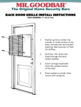
FRAMING CONSIDERATIONS (steps 1-8)
1A. Framing for Horizontal T&G Application (gure A)
The entire sauna should have 2x4 framing on all four sides and the
ceiling. If a portion of the sauna is solid wall construction (brick,
block, etc.) those walls should be framed with vertical 2x2 ring strips
or standard 2x4 framing. All framing is standard 16” on center.
1B. Framing for Vertical T&G Application (gure B)
If you plan to install your T&G vertically, you have two framing op-
tions.
Method 1: Install 2x2 or 2x4 nailers between the studs (gure B meth-
od 1). For standard 7’ high saunas evenly space and fasten 4 levels
of nailers between the top plate and base plate of your walls.
Method 2: For standard 7’ high saunas evenly space and fasten six
1x2 furring strips across the studs (gure B method 2).
2. Baseplate (gure C)
We recommend the baseplate be constructed of treated 2x4s for
added protection against moisture on the oor. All other framing
can be any suitable framing material such as SPF 2x4s. The oor
should be a waterproof surface such as tile, linoleum or concrete.
3. Ceiling Framing
The ceiling height should be framed at 7’ or less (minimum of 75”)
off the oor. If the ceiling is currently over 7’ it should be dropped for
proper sauna performance (gure D). Generally 2x4 ceiling framing
is adequate but in cases of a span of 8’ or over consider using 2x6
lumber.
4. Corner Studs
Be sure you have a stud in each corner of the room to allow fasten-
ing of the ends of the T&G boards (gure E).
C
E
D
Figure A
Framing for HORIZONTAL tongue &
groove application
Top plate
Insulation
Foil vapor barrier
Staples
Tongue & Groove
Leave at least 1/4” gap o oor
Air inlet box
Base plate
Figure B
Framing for VERTICAL tongue &
groove application
METHOD 1
METHOD 2

12/18/18
R.D. TF
710-0101 Custom Cut Installation
Rev. 05
Page 4
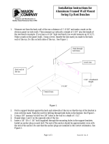
5. Framing the Doorway
Make sure to frame your doorway perfectly plumb and square. Frame
theleft and right sides with a double 2x4 for added strength (gure F).
For a standard wood door create a rough opening (R.O.) 2” wider
and 2” taller than the door size ordered. A standard wood door is 24”
x 80” and the R.O. should be framed to 26” x 82”. For a standard all-
glass door, frame your R.O. 3-1/2” wider and 2” taller than the door size
ordered. A standard all glass door is 24” x 80” and the R.O. should be
framed to 27-1/2” x 82”. See specications supplied with any custom
door.
NOTE: If you have a handicap (ADA) door, leave the baseplate clear
for wheelchair access.
NOTE: If using a standard 80” door, it is typical to have no threshold. If us-
ing a 72” door, a single (1-1/2”) or double (3”) threshold may be desired.
6. Framing for Air Inlet
Every sauna should have two vents; an air inlet and air outlet. The air
inlet should be located just below the heater at oor lever. Using 2x4s,
create a box with inside dimensions of 6” x 4”. It is easiest to incorporate
a wall stud for one of the sides of your box and the base plate to com-
plete the bottom of your rectangle (gure G).
7. Framing for Air Outlet
The outlet vent should be located as far from the inlet as possible, di-
agonally across the room. Frame the opening the same size as the inlet
(6” x 4”) with the top of the opening 23” off the oor in standard situa-
tions. It is not recommended to install the outlet any higher than 30” to
ensure minimal loss of heat from the sauna. Again, use an existing stud
for one side of the vent. Additional 2x4s will need to be cut to form the
other 3 sides of the vent.
8. Framing for Heater Mounting Bracket
Determine the location of the heater in the sauna as recommended by
your sauna representative or as described by your heater installation in-
structions and template supplied with the heater. Add two 2x4 supports
between the studs for the heater brackets (gure I).
NOTE: The metal heater hanging brackets are installed after the T&G instal-
lation. The height and location of the supports is determined by the
mounting instructions supplied with the heater. The 2x4 supports are not
needed when using the optional oor stand or commercial oor stand-
ing heaters.
9. Electrical Rough-In
Once the sauna is fully framed, and before the insulation is installed, the
electrical rough-in should be done by a licensed electrician.
Warning: Follow wiring instructions provided with the heater. Always use
proper wire size and type as specied in your heater instructions pro-
vided in your heater box.
Heater: Your wires will enter your sauna heater from below (gure I). Be
sure to allow enough extra wire (typically 18”) to make nal hook-up
easier.
Light: The light can be mounted on a wall of your choice. Most common
is off to one side of the door. Have wire run wire accordingly.
H
F
G
I
Double
2x4s
6” x 4” air inlet vent
hole
6” x 4” air outlet
vent hole
heater wire inlet vent hole

12/18/18
R.D. TF
710-0101 Custom Cut Installation
Rev. 05
Page 5
10. Insulation - Always refer to local building codes.
Using R11 or better unfaced berglass bats, insulate the interior walls of
your sauna by tucking it between the studs. NOTE: Un-backed batts are
best to prevent a double vapor barrier which could trap moisture. If
you only have backed insulation keep the paper/foil side to the inte-
rior of the room. For the ceiling use either a single layer of 6” berglass
(gure K) or you may wish to use a double layer of 3-1/2” berglass. To
do this, hang the rst layer perpendicular to the ceiling joists and then
pound nails into the bottoms of the joists and hang the second layer
on the nails between the joists.
11. Vapor Barrier
Your custom-cut sauna kit comes with a roll of foil vapor barrier. The foil
has a dual purpose acting both as a vapor barrier and heat reectant.
Apply the vapor barrier to the inside framing using staples being sure
to cover all walls and the ceiling. Roll it out horizontally covering the
bottom of the walls rst and working your way to the top overlapping
about 5” (gure L). If desired, you can tape the joints using foil tape
(not provided).
Tongue & Groove Installation
Custom cut packages include tongue and groove (T&G) lumber
already cut to specied length. Each package of boards is labeled for
location and the sequence in which it is installed... (1. Ceiling, 2. Back
Wall, 3. Side Walls, 4. Front Wall). Also, the benches are pre-built and
the door is pre-hung. Refer to your custom cut worksheet as a guide
for sequence.
OPTION: Your T&G boards may vary in shade particularly with cedar or
redwood. To make a nice transition, lay out all your boards for a given
wall in a pattern from light to dark (gure M). In general cases fasten
your lighter boards towards the top of the wall and darker ones to-
wards the bottom, but personal preference is the rule.
Warning: We recommend using only galvanized or stainless steel
fasteners to help prevent corrosion. Your custom-cut kit includes some
stainless steel screws and coated screws.
12. Ceiling T&G
Install the ceiling boards before the walls so the ceiling boards are
supported at their edges. Your ceiling boards will be installed perpen-
dicular to your ceiling joists unless you have special nailers installed.
Face-nail through the board on each end staying far enough away as
to not split the wood (gure N). These nail heads will later be covered
by trim. Blind-nail through the tongue into the joists (gure p).
Place the toungue of the rst board up against the wall. Face nail on
both ends and blind nail through the groove at each joist.
Note: Measure each end after installing every 3-5 boards to prevent
“fanning”.
13. Continue with the other ceiling boards, face-nailing through the
ends and blind-nailing at each ceiling joist. Your last ceiling board
most likely will need to be ripped in order for it to t.
K
L
N
Face-nail ends
P
Blind nail
through
grooves with
pin nailer.
Tongue towards
wall
M

12/18/18
R.D. TF
710-0101 Custom Cut Installation
Rev. 05
Page 6
Top Down method.
Level the top board along each wall
Horizontal Wall T&G
In general cases the interior T&G boards are provided at proper
length so no cutting is necessary. This length is slightly shorter than
the wall to prevent binding and tearing of the vapor barrier. In some
saunas the front/door wall T&G boards are sent longer than needed
so they can be cut to t once the door framing is complete; de-
pending upon information provided at the time of order.
NOTE: It is recommended to install the T&G with tongue side up. This
will help prevent any moisture from collecting in the groove.
*If you are doing a Vertical T&G installation go to step 17.
15a Horizontal Wall T&G Installation “Top Down” Method
(when using a pin nailer)
Start at the top of the back wall and position your rst piece of T&G
along the wall with the tongue towards the ceiling. Making sure it is
level (gure Q), nail it into place using the same method shown for
the ceiling T&G; face nail along the ends and blind nail on each of
the studs. Any gaps between your ceiling and your top wall board
will later be covered by trim. Go to step 16.
15b Horizontal Wall T&G Installation “Bottom Up” Method
(when using a hammer and galvanized nails)
In order to keep your T&G application level and dry it is necessary to
rst put a starter board at the bottom of each wall. Find the highest
point on the sauna oor to use as a reference. Assuming your ceil-
ing is level, measure down from it in each corner and mark a com-
mon distance (1/4” minimum) short of your reference point in each
corner.
Hint: Keeping your boards off the oor prevents them from soaking
up any moisture that may accumulate there.
NOTE: Do not take measurements up from the oor since you want
the top board of each wall to be level with your ceiling. If there is a
signicant slope to the oor (1 inch from one side to the other) rip
your bottom board at a taper to allow for this slope. It is important to
install your bottom starter row perfectly level along all walls making
sure the groove ends are matched up in the corners (gure R). This
rst row acts as a guide for the rest of the interior T&G installation.
16. Continue fastening your T&G along the wall (gure S) till you reach
your last board either at the top or bottom. You may need to rip
your last board to t making sure your bottom board is at least 1/4”
off the oor. Finish the rest of the interior in the order of back wall,
side walls, and lastly the front (door) wall.
HINT: When installing the short pieces on each side of the door or
windows use a full length board as a guide to keep the pieces on
both sides aligned and level; then nail them into place (gure T).
*Continue with step 19.
T
Q
S
Bottom Up method.
Keep starter row at least 1/2” off the oor.
R

12/18/18
R.D. TF
710-0101 Custom Cut Installation
Rev. 05
Page 7
17. Vertical Wall T&G
Your rst board on each wall should be fastened with the tongue side
towards the corner if you are using a pin nailer and the groove side
towards the corner if using hammer and nails (as was done for the
ceiling). It is easiest to work from left to right if you are right handed
and vice versa. Always butt your vertical boards against the ceiling to
keep them about 1/4” off the oor. Face nail your boards at the top
and blind nail them at each nailer as was done for the ceiling (gure
U). Your interior trim will later cover the nail heads at the top.
HINT: When installing short pieces above or below a window, use a
full length board as a guide to keep the short pieces aligned and
level (similar to gure T but with a vertical orientation).
18. Keeping your boards vertical, continue blind nailing them into
place along the walls until all your walls are covered. Your last board
on each wall may need to get ripped in order to t into the corner.
19. Vent Valve
The vent valve is to be placed over the outlet vent hole in the interior
of the sauna. Slide the valve door open and place the opening di-
rectly over the 6” x 4” cutout. Making sure it is level, fasten it with two
1-1/2” screws (gure V).
20. Vent Grill
From the outside of the sauna, center the wood grill over the exterior
of the 6” x 4” cutout, with the louvers facing down. Making sure it is
level, fasten with four 1-1/2” screws (gure W). If your back wall is hid-
den, the grill is not needed.
NOTE: In most cases the inlet vent under the heater will be covered
by the heater so no grill or trim is needed on the inside; the outside
grill is provided. If you must place your inlet vent in a location other
than below the heater you can purchase another vent grill from your
supplier.
21. Bench Supports
In most cases your lower benches have longer supports to allow them
to be slid in and out for easy cleaning. Measuring from the oor, mark
a line at 12” and 30” on the walls where your bench supports will be
fastened. These measurements will be the top edge of the 2x4 sup-
ports. Each support is long enough to span at least 2 wall studs. This
will allow for at least two 3-inch screws, per support, to be anchored
into wall studs for necessary strength. Making sure they are level,
position them on the wall and use 3” screws to secure the supports to
the walls (gure X).
NOTE: By using the above measurements your nal bench heights will
be approximately 18” for the lower and 36” for the upper benches. If
you have a ceiling height other than 7’ these bench heights can be
adjusted for head clearance or better heat.
W
U
X
Face-nail along top
Blind-nail at each
horizontal nailer
Upper bench support
Lower bench support
V
Screws into studs.

12/18/18
R.D. TF
710-0101 Custom Cut Installation
Rev. 05
Page 8
BB
DD
AA
CC
NOTE (for saunas with an L-shaped top bench): On saunas having
an L-shaped top bench, you will have an additional upper bench
support. Fasten them to the walls so the tops are 30” off the oor.
Two 3/8” holes have been drilled through the frame of the upper
L-bench. With the top of the upper benches aligned, use a 3/8” drill
bit and drill through the 2 provided holes and through the face of
the main upper bench. Bolt the two benches together using the 5-1/2”
carriage bolts provided (gure Z).
22. Cove Molding
The cove molding (3/4” x 1”) will be provided longer than needed to
allow trimming to exact size to insure a tight t. Measure each wall to
determine cut length. A simple butt-end cut is the easiest. Cut mold-
ing straight, then butt the pieces together (gure AA). If you prefer a
mitre joint, the molding is long enough to accommodate that type
of cut as well. Using #4 nishing nails, nail the cove molding to the
walls.
23. Corner Molding
The corner molding (3/4” x 3/4”) is used to trim the corners of the
room where the walls meet (gure BB). On corners without benches,
cut molding full length and install with nishing nails. On corners with
benches, cut the molding in two pieces; one from the bench surface
up to the cove molding and the other from the bottom of the bench
support down to the bottom of the wall T&G.
24. Backrest (not included with all models)
Position your backrest in the mid-back/shoulder blade area, whatever
feels most comfortable. A typical height is 20” from top of bench
to top of backrest. Making sure it is level, hold the backrest at your
preferred height, fasten it to the wall through the predrilled holes,
using 2” screws (gure CC). Wood plugs are provided to cover the
exposed screw heads.
25. Interior Light
The light should be wired by a licensed electrician according to lo-
cal codes.
Mount the light in the location where your wire comes through the
wall (gure DD). If you plan to use a corner lampshade, the light will
need to be installed tight into a corner approximately 4” down from
the cove molding.
Note: Lighting systems vary, please refer to specic manual for light-
ing information.
26. Sauna Heater
The heater should be wired by a licensed electrician according to
the specications provided with the heater. The mounting instruc-
tions are provided with the heater.
Bolt
upper L-bench
upper main bench
Underside View
Z

12/18/18
R.D. TF
710-0101 Custom Cut Installation
Rev. 05
Page 9
GG
II
HH
27. Rock Placement (Very Important)
Rinse the rocks before placing them in the sauna heater. Place the
smaller and atter rocks around the outside of the rock compart-
ment and the larger rocks in the center (photo DD). This will allow for
good air transfer through the heater. Do not try to force all the rocks
in, It is important to have space between the rocks to give optimum
heater performance, faster heat-up time and higher temperatures.
Save your extra rocks for replacements.
28. Heater Guard
Place the heater guard around the heater as described in your
heater instructions; spacing may vary according to heater kilowatt.
Making sure it is level, fasten it to the wall with 2” screws (gure FF).
NOTE: The front rails of the 2-sided heater guard can be cut to de-
sired length before assembly.
29. Door Installation
The door is pre-hung with a jamb. Please note that sauna doors must
always swing out. Remove the screw securing the door to the jamb
which was in place for safe shipping.
30. Place the door into the framed opening and fasten the hinge
side to the 2x4 frame using provided 3” screws. Mount so the door
jamb is ush with the surface of the exterior wall material. Be sure
the door is level and plumb. If it is not., use shims between the op-
posite side jam and frame. Check for uniform spacing at the top of
the door and jamb then continue to fasten around the frame (gure
GG).
Note: If using a wood door for an outside sauna application, it is
recommended to seal the door on all sides including the edges to
prevent condensation damage. (All six sides)
31. After the door is secured in place, install the jamb extensions if
provided (gure HH). The jamb extensions should be ush with the
surface of the T&G on the interior sauna walls. The tapered edge
of the jamb extension butts up against the existing door jamb. The
easiest way is to nail the extension to the side of the framed opening
(an alternative method is to attach the extensions to the door frame
itself). After jamb extensions are secured, install the interior door
casing provided. The casing should cover most of the jamb exten-
sions (leave about 1/8” of jamb showing for a reveal). Nail to the
jamb and to the walls inside the sauna room The exterior of the door
is typically trimmed to match the molding in the adjacent room. If
exterior T&G was purchased, extra trim is provided.
32. Door Handle
A pair of door handles is provided with each door. Using the screws
provided, install the door handles with the center of the handle
approximately 36” off the oor (or whatever height is most comfort-
able). After the handles are fastened, install the provided wood
plugs to ll the holes.
FF
Tapered edge
DD
large rocks in the middle
smaller/ atter rocks in the
front and back
/