Page is loading ...

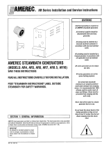
Heater imensions:
18-1/2" wide. 28' high. 12' deep.
WARNING
Do not take a sauna if using
alcohol, drugs or medications.
Pregnant women or persons with
poor health should consult their
physician before using any sauna.
Caution fire hazard: Do not use the
sauna room for drying clothes,
bathing suits, etc. Do not hang
towels above heater or place any
abject other than the rocks
supplied on the heater. If any
darkening of the wall around the
heater is noticed discontinue
sauna use immediately.
Inspect sauna regularly for
required maintenance to heater,
control and benches. Replace
wood surfaces which show any
signs of deterioration.
The heater gets extremely hot
during operation and should not be
touched or burns may result.
Minors should be adequately
supervised whenever near a hot or
warming sauna.
Fire sprinkler systems used inside
any sauna room should be
properly rated for sauna room
temperatures.
Do not pour chlorinated pool or
spa water on heater. Excessive
water use on heater may cause
damage and void warranty.
Electric Shock Hazard - High
voltage exists within this
equipment. There are no user
serviceable parts in this
equipment. All installation and
service to this equipment should
be performed by qualified
licensed personnel in accordance
with local and national codes.
"""AMEREC
INSTALLATION AND SERVICE INSTRUCTIONS
AMEREC SAUNA HEATER
WALL MODELS
WB7.6, WB8.3, WB1
0
Read all instructions carefully before installation. Please leave all
instructions and warranty with the owner. Please fill out and return
your warranty certificate promptly.
ill
WARNING
Prolonged exposure to elevated temperatures is capable of inducing hyperthermia.
Hyperthermia occurs when the internal temperature of the body reaches several
degrees above the normal body temperature of 98.6°F. The symptoms of hyperther-
mia include an increase in the normal temperature of the body, dizziness, lethargy,
drowsiness, and fainting. The effects of the hyperthermia include failure to perceive
heat, failure to recognize the need to exit the room, unawareness of impending
hazard, fetal damage in pregnant women, physical inability to exit the room and
unconsciousness.
WARNING
The use of alcohol, drugs, or medication is capable of greatly increasing the risk of
fatal hyperthermia
SECTION 1: GENERAL INFORMATION
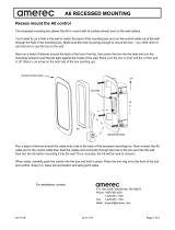
AMEREC Sauna Heaters are listed by Underwriters Laboratories. These heaters are for permanent
installation and electrical connection. To determine the correct wire size and circuit protection
refer to the Heater Specification Chart below.
DIAGRAM 1
HEATER SPECIFICATION CHART
HEATER
MODEL
VOLTAGE
PHASE
KW
—
AMPS
MINIMUM
90r 0
COPPER
SUPPLY WIRE
A.W.3. NO.
_
MINIMUM ROOM
MAXIMUM ROOM
FLOOR
AREA
CEILING
HEIGHT
VOLUME
CU. FT.
CEILING
HEIGHT
VOLUME
CU. FT.
W87.6
240
1
7.8
31.7 8-2 W/G
28 Sq. R.
7W
250
98'
425
W88.3
240
1
8.3
34.8
8-2 W/G
28 S. R.
78'
275
gt
475
W810
240
1
10
41.7
8-2 WIG
28 So. R.
78'
375
38'
803
—
25% less if 208 VAC single phase used instead of 240 VAC.
4211-46 798

I
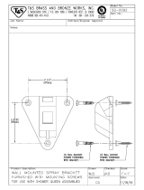
DIAGRAM 3
•
•
0
0
51
0
NOT USED
TEMPERATURE CONTROL WIRING DIAGRAM
-
01-.0 0 AO
Or 0'
3
'0
-
10r0
-
ff
7'
"r
_L
0
MD WING
I
NAMEREC INSTALLATION AND SERVICE INSTRUCTIONS
page
2 I
DIAGRAM 2
1-1
ELEMENT
MODEL
A
W87.6
2600W 5000W
W88-3
3333W 5000W
W810
5000W 5000W
240V
IHMCISIAT
TIMER
The temp/time control comes standard mounted on the heater. Alternatively, it may be mounted remote from
the heater outside the sauna room. If this location is chosen see Section 5: for wiring instructions.
4211-56 1/98

I SECTION 3: SAUNA ROCKS
SECTION 2: SECURING HEATER TO THE WALL
•
The sauna heater comes completely assembled.
Attach the brackets supplied to the wall as
shown in Diagram 4. The bottom of the heater
should be not less than 12 inches from the floor
and the top of the heater at least 40 inches
below the interior ceiling and not less than 4
inches from adjacent wood surfaces. Do not
install benches over top of heater.
SECTION 5: TEMPERATURE CONTROL
1////AMEREC
INSTALLATION AND SERVICE INSTRUCTIONS
page 3
This heater must not be operated unless the rock
compartment in the top of the heater is filled with
the igneous rocks that are furnished with the
heater. They should be put on the heater so that
the air is free to travel around them. Do not pack
too tightly.
SECTION 4: ELECTRICAL WIRING
All wiring must be accomplished by a licensed
electrical contractor. Referto the Heater Specifi-
cation Chartto determine the wire size and circuit
protection required. The cam plete sauna system
consisting of heaterandtempitime control should
be properly grounded as per NEC or as required
The temp/time control comes standard mount-
ed on the heater. Alternatively, it may be
mounted remote from the heater outside the
sauna room.
If this location is chosen (5) #10
AWG wires (including ground) plus (2) AWG
wires from terminals 5 & 6 of the same size as
listed on the heater specification chart on
page #1 must be run from the control location
to the heater junction box in 2 separate con-
duits, (additional remote wiring and conduit
not included). See Diagram 3.
If mounted
remote from the heater, the temp/time control
rough-in box should be installed flush in the
wall, 5 feet up from the floor and so the opening
is to the outside of the sauna room wall. A blank
cover plate is included with the heater to cover
the heater mounted control location when the
control is mounted remote from the heater. The
control is prewired and coded to simplify the
field wiring. The capillary tube of the thermo-
stat may go out through any knockout in the
3-
gang rough-in box (not provided).
The rough-
During the first operation, the rocks should be
heated for two hours at maximum temperature
with no one in the sauna room. This will ailowany
concealed moisture to be evaporated. If not, the
moisture could cause the rocks to crack and
possibly project fragments.
by local codes. Grounding terminals are provided
in the wiring compartments of each heater and
also in the temp/time control. Complete the
wiring according to the appropriate Diagrams
1 & 3.
in box should be a minimum 67.3 cubic inch
3W deep style. The preferred method is to run
the tube within the wall as shown on diagram 4.
The grommet furnished with the control is to
protect the capillary where it leaves the rough-
in box. Capillary tubing which is exposed on the
surface of the sauna wall must be covered with
wooden molding. Mount the capillary tube so
the tip of the bulb is on the centerline of the
heater, 24' down from the ceiling. The capillary
tubing bulb shall be covered with the protective
shield furnished with the control. The screws
for attaching the shield are included.
Caution:
The tubing should be uncoiled carefully--the
minimum bend radius of the tubing is 1/4
inch. Damage to the tubing will make the
heater inoperative. The electrical wiring of
the control should be as shown in Diagrams
3 & 4.
WARNING
Do not locate benches over
heater. Minimum height of ceiling
above heater 40' .
Do not construct sauna room so as
to restrict air flow through the
bottom of the heater.
Minimum clearance from heater to
wooden surfaces (benches, side
walls, heater fence etc.) 4 inches.
Mounting brackets supplied.
Provides proper clearance from
wall behind heater.
Rock preheat required. Although
the rocks are specially selected for
use with this sauna heater,
concealed moisture could cause
the rocks to crack and project
fragments causing potential
injury when the rocks are heated.
The rocks must be preheated on
the sauna heater for two hours at
maximum temperature with no one
in the sauna room.
Packing the rocks too tightly may
cause the heater high limit switch
to trip.
Use only copper wire of the size
and type indicated in the Heater
Specification Chart and the
temperature rating indicated on
the heater junction box.
All heaters and controls must be
grounded per NEC to prevent
electrical shock in case of unit
failure.
The tubing should be uncoiled
carefully--the minimum bend
radius of the tubing is
11e.
Damage to the tubing will make
the heater inoperative.
4211-56 1/68

HAMEREC
INSTALLATION AND SERVICE INSTRUCTIONS
page 4 I
4
211-56
'198
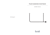
DIAGRAM 4
HEATER WITH HEATER MOUNTED CONTROL
-* Capillary bulb protective cover. Locate tip of
bulb 24' down from the ceiling on the center-
line of the heater.
Note: If tubing
is
exposed on surface of the
sauna wall, cover with wooden molding.
1
I
Limit
Switch
Reset.
See
Section 6.
12"
min.
Power
in from breaker box. Flex conduit Pro-
vide three feet into room ounng rough-in.
Limit
Switch
Reset.
See
Section 6.
1
12"
min.
Control wiring.
Power in from breaker box. Flex conduit Pro-
vide three feet into room during rough-in.
CD
Provide 2 x 4 blocking so brackets can be securely fastened to the
wail with the four screws provided.
0 Power supply connection wire size determined f rom size of heater
used. (See Heater Specification Chart)
Note:
Do not locate benches over heater.
Do not construct sauna so as to restrict air flow through bottom of
heater.
Minimum clearance from heater to wooden surfaces (benches,
walls, heater guard rail, etc.) is 4 inches.
Use only copper wire of the size, type and temperature rating
indicated in the Heater Specification Chart and the heater junction
box.
HEATER WITH WALL MOUNTED CONTROL
•
-
•
Capillary
bulb protective cover. Locate tip of
— bulb 24' down from the ceiling on the center-
line of the heater.
Grommetto protect capillary tubing.
Note: If tubing is exposed on surface of the
sauna wall, cover with wooden molding.
Temperature control box. Face out from
sauna room five feet up from floor for remote
mounting installations.

WARNING
Electrical outlets or receptacle
must not be installed in a sauna
room.
A guardrail or fence is required
around the heater to prevent burns
from accidental contact.
The 'Caution' and `Warnings
placards must be mounted In
accordance with Section 9.
WARNING
REDUCE THE RISK OF OVERHEATING
• Ed Wrenn* it incorriodatile, dizzy, or
slow Stayng too long r a sawn is cassoie
at causing overneing.
&penis children et ail times.
Puck wth a drxior Caroni use if
;want
In
Poor been a under medical care.
Breit* heated at In cceenclon wth
cartortdon at natal, drugs, or trodkation
is arcade at cash" unconsciousness
L
CAUTION
REDUCE THE RISK CF ARE
On NW Non °rime, WNW On
O•
near
AMA
Tlwa
SECTION 7: ELECTRICAL OUTLETS OR RECEPTACLES
SECTION 3: HEATER GUARD RAIL
SECTION 9: PLACARD
SECTION 10: THERMOMETER/HUMIDITY GAUGE
SECTION
11:
BUCKET & DIPPER
prillEREC
INSTALLATION AND SERVICE INSTRUCTIONS
page 5
This heater is equipped with an overheat safety
device. In the event of an abnormal heating
condition, the heater will automatically shut off
and the heater cannot be turned on again until the
heater cools. The reset button is located on the
center of the back of the junction box, under the
painted shell. See Diagram 4. Pushing on the
reset button, afterthe cooling period, will restore
Caution:
Electrical outlets or receptacles must not
be installed in a sauna room.
If an intercom speaker is to be installed in a sauna
room, it should be of the outdoor metal type and
should be installed away from the sauna heater
and as low to the floor as possible. The sauna
It is required that a guard rail or fence be con-
410
structed around the sauna heater to prevent the
bather from making physical contact with the
heating unit. The guard rail must not be closer
Two metal placards are included in the Installa-
tion Instruction Envelope packaged with every
Amerec Sauna Heater. The CAUTION placard
must be attached to the interior wail of the sauna
(Not furnished with heater. Available from your
AMEREC dealer.) Locate 6' down from ceiling on
wall so that gauge can be observed from out-
side sauna room through door window.
(Not furnished with heater. Available from your
AMEREC dealer.) Dippers have long wooden
handles to help keep from exposing hand to
powerto the heater. if the reset button continues
to trip, the factory service person should be
notified.
Note:
Packing the rocks too tightly may cause the
heater limit switch to trip.
room light should be a wall bracket type and the
rough-in box should be flush with the inside
finish material. The recommended height is 70'
up from the floor. If a ceiling light is to be used,
it should bean approved type with a junction box
that is remote to the fixture itseif. Use only a
fixture that utilizes A.F. or fixture type internal
wiring.
than two inchesto the exterior walls of the heater.
If the heater is to be located in the comer of the
room, one section of the guard rail may be
deleted. See diagram 5.
room directly above the heater where it is visible
to the bather. The WARNING placard must be
attached to the door of the sauna room. Nails for
attaching the placards are furnished.
Temperature displayed on the thermometer
during the initial heat up will tend to lag actual
room temperature by 10 to 15 degrees.
steam. Do not pour chlorinated pool or spa water
on heater. Excessive water use on heater may
cause damage and void warranty.
SECTION 5: RESET BUTTON
•
4211-56 '/98

DIAGRAM 5
GUARD RAIL INSTALLATION
HEATER MOUNTED AT CENTER OF WALL
HEATER MOUNTED AT CORNER OF WALL
SECURE
Z142 POST
4'
TO WALL
WITH
SCREWS
SECURE
772
POST
TO WALL
WITH
SCREWS
4'
181/2'
4'
SECURE
2X2 POST
TO WALL
WITH
SCREWS
4
\
SECURE
2X2
POST
TO WALL
WITH
SCREWS
4211-58 1/98
O
NIEREC
INSTALLATION AND SERVICE INSTRUCTIONS
page 6 I

SECTION 13: OPERATING INSTRUCTIONS
//////AMEREC
INSTALLATION AND SERVICE INSTRUCTIONS
page
7
Referto the Heater Specification Chart on page 1
to confirm that the room size and the heater
model are to the correct specifications.
Wall Framing:
Masonry or concrete walls to
be
stripped with 2 x 4 dry framing material on 16
inch centers to provide nailing for wall paneling.
Frame walls to be standard stud walls. If interior
cedar is to be mounted vertically, horizontal
furring strips are required.
Insulation:
Full thick foil faced fiberglass blanket
with a minimum 'R'factor of 11 for both walls and
ceiling. Aluminum foil facing into room.
Ceiling Frame: Ceiling
height 84', see preferred
minimum/maximum ceiling heights on the Heat-
er Specification Chart. Diagram 1. Ceiling joists
2x 4, 2 x 6 or 2 x 8 dry fir 16 inch center.
Plasterboard:
(when required by code) 5/8' gyp-
sum wallboard, one hourfire rated. Apply on wall
and ceiling framing before interior finish.
Interior Finish:
1 x 4 V-joint T&G vertical grain
KD cedar. All boards full length. Blind nail with 5d
galvanized nails or equivalent power stapling.
Benches:
1 x 4 or 2 x 4 clear VG cedar with 1 x 4
or 2 x 6 face and frame members. Use galvanized
nails and fasteners, concealed where possible.
Heater Guard Rail:
Clear VG KD cedar (see
Section 8).
Sauna Door:
Amerec pre-hung model G2P of
solid core fir complete with clear tempered,
hermetically sealed glass, wooden door pull and
self closing hinge. Sauna door must open out and
not lock.
A COMPLETE LINE OF ADDITIONAL SAUNA AC-
CESSORIES ARE AVAILABLE FROM YOUR
AMEREC DEALER.
Upon completion ot the sau-
na installation, please leave all instructions
and warranty with the owner.
Congratulations and thank you for choosing
AMEREC. Your new AMEREC Sauna Heater and
Control have been designed and constructed to
give you the most in performance, economy and
comfort. The following information is presented
as a guide to help you getthe most pleasurefrom
your new sauna room.
Ventilation Openings:
Amerec heaters do not
requireventilation openings. Rooms may or may
not be provided with ventilation openings. If
ventilation openings are desired, it is recom-
mended that the openings meet the require-
ments of UL Specification 875, paragraph 41.7A
as follows:
41.7A I nletventilation opening shall be located at
the bottom of the wail, as close to the floor level
as possible. The minimum size of the ventilation
openings for a room shall be determined using
one of the following formulas:
For R < 31: V 9.3,
For R 31: V 0.3R,
In which:
R
is the floor area of the room in square feet,
and
V
is the total minimum area of ventilation
openings in square inches.
For the SI system of units, the equations are:
For R < 2.9: V ?_ 60,
for R 1. 2.9: V 20.8 R,
In which:
R
is the floor area of the room in square
meters, and
V
is the minimum area of ventilation openings
in square centimeters.
Outletventilation openings shall be located atthe
top of the wall, as closetothe ceiling as possible,
and shall meet the same minimum size require-
ments as for inlet ventilation openings.
To Heat the Sauna Room:
The circuit breaker
in the house panel that provides power to the
sauna heater should be left in the ON position.
This breaker should be turned OFF if the sauna
is not to be used for an extended period of time,
or if the sauna is to be serviced.
SECTION 12: ROOM CONSTRUCTION (Architectural Recommendations)
SEE DIAGRAMS
WARNING
For safety purpose sauna door
must open out and not lock.
Never use a wood stain, seal or
preservative on the inside of your
sauna room.
4211-38 1198

I
phIEREC
INSTALLATION AND SERVICE INSTRUCTIONS
page 8
SECTION 13: OPERATING INSTRUCTIONS (Cant.)
et
First time use:
When turning on your sauna for the first time
follow steps 1 and 2 through two cycles and let
the heater run with no one in the sauna room a full
120 minutes. This will allow excess oil to burn off
the heating elements without causing any dis-
comfort to the bather and also complete the
rock preheat requirement outlined in Section 3.
Normal Operation:
Step 1:
Set the temperature control knob on 10.
This is the highest heat setting.
Step 2:
Turn the one hour timer to its maximum
setting (60 minutes).
Step 3:
Observe the wall thermometer (heat
indicator) in the sauna room (6' from the
ceiling). When it shows a temperature that
feels satisfactory to you (160° to 180° F
is
normal) slowly rotate the temperature knob
from 10 back towards the OFF position until you
hear a click
and
the red heat indicator light goes
out. At this setting the heat will cycle ON and
OFF and maintain approximately the tempera-
ture now appearing on the wall thermometer.
After you have used the sauna a few times, you
should be able to determine the number of the
temperature setting that will giveyou the temper-
ature you prefer for your sauna bath.
Step 4:
After you have finished your sauna bath
turn the switch OFF. The timer switch may be
advanced at anytime during your sauna, or it will
automatically shut the heater off when time has
expired.
Note:
Your temperature control has a red heat
indicator light: this glows only when power is
actually going to the heating elements.
The sauna, like a bathroom, should
be
kept clean
and odor free.
Towels or mats should always be used on bench-
esand floor as perspiration otherwise penetrates
the soft wood.
Air out the sauna often by keeping the door and
vents open when the sauna is not in use. Saunas
that are in daily use should be washed down at
least once a week to keep them clean and the air
fresh. buckboard should be removed from the
sauna, the sauna floor mopped and dried in a
conventional manner, and the duckboard thor-
oughly scrubbed and dried before returning to
the sauna room. The sauna heater should be
wiped down occasionally with a damp cloth to
remove lint and dust. The rocks should be re-
moved once a year for cleaning and small or
crumbled rocks replaced.
To clean and remove perspiration stains, use
soap or detergent in warm water, best applied
with a scrub brush. Badly soiled surfaces may
require sanding. Sand paper wrapped around a
wooden block works well.
Benches and supporting structure must be in-
spected annually for potential deterioration due
to age, dry rot or abuse. Any boards with signs of
deteriorations should be replaced immediatelyto
avoid possible injury.
SECTION 14: MAINTENANCE
i
/
F4t
R
o
l
:
ER
r
a
CE!
•
4211-56 1/98
lassefictured
b
r
nasaccir
P.O.
Box 40550 Mims, WA USA 96015
(425) 643-7500 (88:1) 331-0349
FAX: (425) 543-2124
/