Pottinger VITASEM 252 Operating instructions
- Category
- Kitchen & houseware accessories
- Type
- Operating instructions
This manual is also suitable for

Operator‘s manual
GB
+ INSTRUCTIONS FOR PRODUCT DELIVERY . . . Page 3
"Translation of the original Operating Manual" Nr. 99 8611.GB.80R.0
Seed drill
VITASEM 252
(Type 8611 : Chassis-Nr: + . .01307 / MaschNr: + . .02307)
VITASEM 302
(Type 8612 : Chassis-Nr: + . .04090 / MaschNr: + . .05090)
VITASEM 402
(Type 8613 : Chassis-Nr: + . .01610 / MaschNr: + . .02610)

1500_GB-PAGE 2
Product liability, information obligation
Product liability obliges manufacturers and dealers to issue operating instructions for the machine at the point of sale and to instruct
the customer on the operation, safety and maintenance regulations governing the machine.
A confirmation is required to verify that the machine and operating instructions have been handed over correctly.
For this purpose
- Document A is to be signed and returned to Pöttinger or via the internet to www.poettinger.at
- Document B remains with the specialist dealer handing over the machine.
- The customer receives document C.
For the purposes of product liability law, every farmer is an entrepreneur.
In the terms of product liability law, damage to property is any damage arising due to the machine, but not to the machine, and an
excess (500 euros) exists for this liability.
Corporate damage to property within the terms of the product liability law is excluded from this liability.
Be advised! The operating instructions must also be handed over with any subsequent machine sale or transfer and the transferee
must be instructed in the regulations stated.
Pöttinger - Trust creates AfÀ nity - since 1871
"Quality pays for itself." Therefore we apply the highest quality standards to our products which are constantly monitored by our
in-house quality management and our management board. Because the safety, perfect function, highest quality and absolute
reliability of our machines in operation are the core competencies for which we stand.
There may be deviations between these instructions and the product as we are constantly developing our products. Therefore no
claims may be derived from the data, illustrations and descriptions. Please contact your Specialist Service Centre for any binding
information about specific features of your machine.
We would ask you to please understand that changes to the scope of supply with regard to form, equipment and technical
specifications are possible at any time.
Any form of reprint, translation or reproduction, including excerpts, requires the written approval of Pöttinger Landtechnik GmbH.
All rights according to copyright laws remain expressly reserved by Pöttinger Landtechnik GmbH.
© Pöttinger Landtechnik GmbH – 31st October 2012
Refer to PÖTPRO for additional information about your machine:
Are you looking for suitable accessories for your machine? No problem! All the information you require is here at your disposal.
Scan the QR code on the machine's type plate or look under www.poettinger.at/poetpro
And if we don't have what your looking for, then your Specialist Service Centre is there for you with help and advice.

Dokument D
GB-0600 Dokum D Anbaugeräte - 3 -
PÖTTINGER Landtechnik GmbH
Industriegelände 1
A-4710 Grieskirchen
Tel. 07248 / 600 -0
Telefax 07248 / 600-2511
T Machine checked according to delivery note. All attached parts removed. All safety equipment, drive shaft and operating
devices at hand.
T Operation and maintenance of machine and/or implement according to operating instructions explained to the customer.
T Tyres checked re. correct pressure.
T Wheel nuts checked re. tightness.
T Drive shaft cut to correct lenght.
T Correct power-take-oɈ speed indicated.
T Fitting to tractor carried out: to three-point linkage
T Trial run carried out and no defects found.
T Functions explained during trial run.
T Pivoting in transporting and operating position explained.
T Information given re. optional extras.
T Absolute need to read the operating manual indicated.
Please check. X
According to the product liability please check the above mentioned items.
INSTRUCTIONS FOR
PRO DUCT DELIVERY
GB
In order to prove that the machine and the operating manual have been properly delivered, a confirmation is necessary.
For this purpose please do the following:
- sign the document A and send it to the company Pöttinger or via the internet to www.poettinger.at
- document B stays with the specialist factory delivering the machine.
- document C stays with the customer.

- 4 -
1500_GB-INHALT_8611
CONTENTS GB
Table of contents
SAFETY
Safety advice .............................................................6
DESCRIPTION OF SERVICES
Overview .................................................................... 7
Versions .....................................................................7
WARNING SIGNS
CE sign ......................................................................8
Warning Signs (symbols) ...........................................8
Meaning of warning signs..........................................8
TECHNICAL DATA
Brief Description of Machine ...................................10
Technical Data .........................................................10
Equipment ...............................................................11
Additional safety notes for VITASEM and
VITASEM A ...............................................................11
Auxiliary Equipment .................................................11
TRACTOR REQUIREMENT
Tractor ......................................................................12
Ballast weights ........................................................12
Lifting Unit (Three-point Linkage) ............................12
Required Hydraulic Connections .............................12
Required Power Connections ..................................12
HITCHING AND UNCOUPLING
Loading .................................................................... 13
Hitching ...................................................................13
Uncoupling ..............................................................13
Tyres: tread/scraper .................................................14
Transport Preparations ............................................14
COMPASS TERMINAL
Performance features of the terminal ......................15
Initial operation ........................................................16
COMPASS terminal .................................................16
Displays and functions ............................................16
Calibration (standard) ..............................................19
Calibration (electrical seed amount adjustment) .....20
Basic setting ............................................................21
Alarm messages ......................................................28
Examples for setting tramlines ................................29
OPERATION
Notes for operation ..................................................30
Hectare counter ......................................................31
Track loosener ........................................................31
Seed drill loosener ...................................................31
Loading ramp ..........................................................31
Releasing harrow rail ...............................................31
Filling seed hopper ..................................................32
Emptying seed hopper ............................................33
Cleaning seed hopper .............................................34
Seed box cover .......................................................35
DOSING
Mode of operation ...................................................36
Fine sowing wheel ...................................................36
Multi-sowing wheel ..................................................37
Adjusting the sowing rate ........................................39
Gear setting / sowing shaft direction of rotation .....39
Cut-off slide .............................................................40
Grain test for oversowing ........................................40
Bottom flap ..............................................................41
Covers (additional equipment) .................................41
Agitator shaft ...........................................................42
Agitator shaft ...........................................................43
Turning agitator shaft ...............................................43
Oscillating agitator shaft ..........................................44
CALIBRATION PROCESS
Set seed rate using the calibration test ...................45
COULTER PRESSURE
Safety advice ...........................................................48
Coulter pressure adjustment ...................................48
Pressure roller ..........................................................48
ROW MARKER
Row marker .............................................................50
HARROW TYPES
Harrow types ...........................................................51
TRAMLINES
Setting up tramlines .................................................52
Tramline rhythm .......................................................52
Adjusting the implement ..........................................52
Switching tramline ...................................................54
Tramline marker .......................................................55
SEED RATE ADJUSTMENT
Electric seed rate adjustment ................................56
TRANSPORT
General Transport Instructions ................................57
MAINTENANCE
Safety point .............................................................58
General maintenance hints ......................................58
Cleaning of machine parts .......................................58
Parking in the open ..................................................58
Winter storage .........................................................58
Drive shafts ..............................................................58
Hydraulic unit ...........................................................58
Maintenance ............................................................59
SERVICE
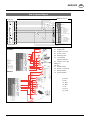
Assignment diagram ................................................62
New assignment diagram ........................................63
Assignment diagram optional extra special
tramlines ..................................................................64
Connection assignment Compass terminal: ...........65
Sensors ....................................................................66
Height adjustment of fill level sensor .......................66
SUPPLEMENT
Combination of tractor and mounted implement ....71
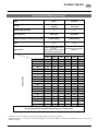
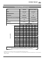
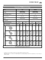
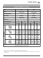
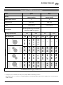
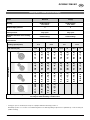
SOWING TABLES
Sowing tables ..........................................................74
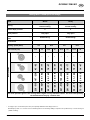
Grain test (for oversowing) ......................................75
Shutter slides position .............................................76
Sowing table VITASEM (normal dosage) .................77
Sowing table VITASEM (normal dosage) .................78
Sowing table VITASEM (normal dosage) .................79
Sowing table VITASEM (normal dosage) .................80
Sowing table VITASEM (normal dosage) .................81
Rapeseed (normal dosage) ......................................82
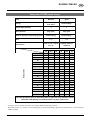
Sowing table VITASEM (electrical dosage) ..............83
Sowing table VITASEM (electrical dosage) ..............84
Sowing table VITASEM (electrical dosage) ..............85
Picture instrction: (13/1) means fig. 13, Position 1

- 5 -
1500_GB-INHALT_8611
CONTENTS GB
Sowing table VITASEM (electrical dosage) ..............86
Sowing table VITASEM (electrical dosage) ..............87
Sowing table VITASEM (electrical dosage) ..............88
Sowing table VITASEM (electrical dosage) ..............89

- 6 -
1300-GB-SICHERHEIT_8521
GB
SAFETY
Safety advice
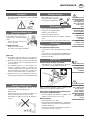
Set the tractor lifting hydraulic system to "Floating position" prior to any hitching and unhitching!
No persons may stand between the tractor and implement during hitching and unhitching; do not enter
the hazard area between tractor and implement when operating the hydraulic system external control!
Danger of injury!
Check that the drilling machine (with folded in track markers) does not touch the tractor when raising.
– e.g. at projecting rear window!
Ensure sufficient steering safety - if the seed hopper is full and particularly as combination; attach
corresponding front weights to the tractor!
Check the tractor and implement for operational and traffic safety every time before they are put into
service! The safety devices must be attached!
The user is responsible for safety!
Do not transport with the seed hopper full!
Climbing onto and riding on the implement (including loading ramp) and remaining in the hazard area
(swivel zone) are not permitted!
Lower the implement, switch off the engine and remove the ignition key before leaving the tractor!
Only perform adjustment and maintenance work with the implement lowered!
Do not reach into the seed hopper and do not place any objects in the empty box, because at gear setting
> “0” any stirring shaft present will turn if the implement is moved; danger of damage and breakage!
When filling dressed seed and cleaning using compressed air, protect parts of body appropriately - the
dressing is irritant or poisonous!
Ensure that there are no persons near the implement before starting up or operating the implement!
On steep slopes (in contour line), take the position of the centre of gravity into account with hydraulic
front drilling machine (combination)!
Prior to first use and after a long period out of use, check the oil level in the transmission and all bearings
for sufficient lubrication; check the tight fit of all bolts. (leakproofness of the hydraulic system) and tyre
pressure!
You should read these Operating Instructions and the safety information ("For your safety") carefully and take heed of
them before taking the drilling machine into service; this includes the instructions for a combined cultivating unit.
The person operating the machine must be qualified regarding the use, maintenance and safety requirements and be
informed about the hazards. Pass all safety instructions on to other users.
The relevant accident prevention regulations as well as the other recognised safety, occupational health and road traffic
regulations are to be observed.
Pay attention to the "Warning signs"!
Notes in these Instructions with this symbol and warning signs on the unit indicate hazards! (See
Attachment "Pictogram symbols" for explanation of the warning signs".)
Loss of warranty
The drilling machine is only constructed for customary agricultural use.
Any other use is deemed not as intended and no liability is assumed for any damage resulting from such use.
Use as intended also includes the observance of the specified operating, maintenance and repair conditions as well as
the sole use of original spare parts.
Use of any accessories and/or parts from other manufacturers (wearing and spare parts) that have not been approved
by PÖTTINGER leads to lapsing of any warranty.
Unauthorised repairs or modifications to the unit as well as any lack of monitoring during use (... sowing quantity and that
all shares sow!) exclude any liability for damage arising therefrom.
Any complaints on delivery (transport damage, completeness) are to be submitted in writing immediately.
Warranty claims and warranty conditions to be observed or exclusion of liability are as according to our terms of delivery.

0900-GB_ÜBERSICHT_8611
GB
- 7 -
DESCRIPTION OF SERVICES
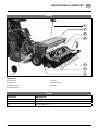
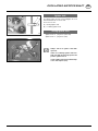
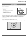
Overview
Designations:
(1) Row marker
(2) Seed hopper
(3) Calibration trays
(4) Loading platform
(5) Harrow
(6) Coulter system
(7) Gears
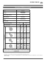
Versions
Designation DESCRIPTION
252 Working width: 250 cm
302 Working width: 300 cm
402 Working width: 400 cm
1
2
3
4
6
7
5

- 8 -
0900_GB-Warnbildzeichen_8611
GB
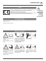
WARNING SIGNS
Read operating manual before initial
operation
Observe safety hints
Observe transport and linkage
advice
CE sign
The CE sign, which is affixed by the manufacturer, indicates out ward ly that this machine con forms
to the engineering guideline regulations and the other relevant EU guidelines.
EU Declaration of Conformity (see supplement)
By signing the EU Declaration of Conformity, the ma nu fac tu r er declares that the machine being
brought into service complies with all relevant safety and health requirements.
Recommendations
for work safety
All points referring
to satety in this
manual are
indicated by this
sign.
Meaning of warning signs
Warning Signs (symbols)
Warning signs are used to indicate possible hazards; their purpose is to help ensure the safety of all those involved in
operating the machine.
Replace any missing warning signs.
After initial operation retighten all
screws; furthermore check regularly
for firm fitting.
For special removal torques see
operating manual or spare parts list.
Use torque wrench.
Travelling on implement during
operation and transportation is
not permitted. Use loading plate
or platform only when machine is
mounted and standing dormant, or
when safely supported.
Swivel out side components. Keep
your distance. Do not enter swivelling
range. Ensure sufficient free space
when swivelling out.
Danger of crushing.
Keep your distance
Rotating implements. Keep your
distance. Do not reach in behind
protection devices or covering
plates, etc.

- 9 -
0900_GB-Warnbildzeichen_8611
GB
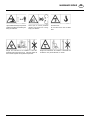
WARNING SIGNS
Danger from load above. Lift “Vitasem” in bulkhead wall
of seed box. Only use textile belts, no chains.
Put notice here
Do not stand in the area of raised
load.
Never open or remove protection
devices when drives are running.
Keep your distance
Danger from load above. Lift “Vitasem A” seed box
bulkhead wall and transport rings. Use belts. Never lift
drill machine together with agricultural implement.
Legs could be hit through components
suddenly swivelling out or sliding out.
Keep your distance.

- 10 -
1300-GB TECHN. DATEN_8611
GB
TECHNICAL DATA
Brief Description of Machine
„VITASEM“ are mechanical three-point hitch seed drills (Category ll).
„VITASEM“ can be equipped either with shoe or single-disc coulters as required,
„VITASEM“ has an optional coulter exchanger for shoe coulters and broad-shoe coulters or single-disc coulters.
Hitching with lower link pendulum compensation (optional extra) ensures good adaption to soil and reliable drive.
The sowing shaft drive comes from the right-hand transport wheel via a continuously adjustable two-directional oil-bath
transmission, which is capable of roughly halving the speed of the sowing shaft, and when set up for „over seeding“, will
also reverse the direction of rotation of the seed shaft.
For 3m the sowing shaft links can be switched off for each side individually.
The special thing about VITASEM is the fact that it has normal output in ”undersowing” with its multi-saw wheels and
individually measures out by changing the rotation direction of the sow shaft e.g. rape-seed in use for ”overseeding”.
To facilitate handling and safe operation the design includes, among others features, a water-proof hopper lid, a functionally
shaped hopper, a feed funnel for each sowing roller, level indicator, individual and central coulter pressure adjustment
and easy-to-perform calibration using the crank.
To adapt the „Vitasem“ to the various types of operation, suitable equipment is available: e.g. various types of harrows,
hydraulic row marker switching and lifting, electronic tramline control incl. a hectare meter and calibration, level indicator
and sowing shaft controller, demarcation of tramlines, hydraulic coulter pressure and seed rate adjustment and a self-
aligning agitator shaft for grass seed and others.
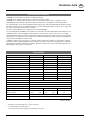
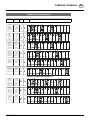
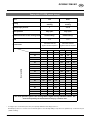
Technical Data
* Pay attention to the transport width of the soil processing device!
** (...) = with rotated wheel mounting (6.00-16),
“eco 302”: with rotated wheel mounting (6.00-16) and with tyres 10/75-15.3
(Subject to alteration)
VITASEM A 252 A 302 A 402
Working width [cm] 250 300 400
Transport width approx. cm 250 * 300 * 400 *
Seed hopper exits 21 25 33
Number of rows: Standard [Option] 21 [14, 17, 20] 24 [17, 21, 24] 32 [23, 27, 32]
Row spacing [cm] 11.9 / 18.3 / 14.9 / 12.5 12.0 / 18.0 / 14.4 / 12.5 12.1 / 17.6 / 14.9 / 12.5
Weight [kg] (without accessories)
... with shares 700 kg
750 kg 1050 kg
... with single-disc shares 730 kg
780 kg 1100 kg
Seed hopper content [l] (large hopper) 480 600 (1000) 850 (1400)
Filling height approx. cm 136 136 / 155 136 / 155
Filling orifice [cm] 200 x 62 250 x 62 350 x 62
Gap between coulters [cm] 30
Disc coulter Ø [mm] 320 x 3
Pressure roller Ø [mm] 250 x 40
Coulter pressure/coulter [kg] 25
Track width approx. cm 230 (250) ** 280 (300) ** 390
Tyres (on request) 6.00-16 (10.0/75-15.3) 6.00-16 (10.0/75-15.3) 10.0/75-15.3
Air pressure[bar] 1.21.2 (0.8) 1.2 (0.8) 0.8
Oil-immersed gearbox filling quantity 2.5 litres (hydraulic oil HLP 32)
Sound pressure level 70 dB(A)

- 11 -
1300-GB TECHN. DATEN_8611
TECHNICAL DATA GB
Additional safety notes for VITASEM and VITASEM A
• Do not reach into the rotating agitator shaft
• Pay attention to safe distances during all maintenance and adjustment work on the machine; rotating and oscillating
machine parts are dangerous.
• Only use foot boards for filling the seed hopper. It is not permitted to travel on the machine under any circumstances.
• Driving on public roads:
- Comply with the regulations issued by your country’s legislative authority.
- Travelling on public roads is only permitted as described in the section “Transport Position”.
- Block all hydraulic circuits.
- Do not place any parts in the seed hopper - the agitator shaft rotates even when manoeuvering
• Protective equipment must be in good working order.
• Pivotable parts must be brought into the correct position prior to starting travel and must be secured against changes
in position which could present a hazard.
• Check that the lighting functions prior to starting travel.
Equipment
- Trailing coulters or single disc coulters
- For Suffolk and wide band coulters, alternatively
equipment with single disc coulters
- Seed hopper with content indicator and folding cover
- Infinitely adjustable, two directional oil-quenched
transmission
- Multi-sowing wheels
- Fine dosing wheel
- Right side of drill shaft can be turned off (half width)
- Calibration system with handle and emptying troughs
- Central coulter pressure adjustment
- Removable supports for dismounting/parking
Auxiliary Equipment
- Fittings for overseeding (e.g. rapeseed)
- Following harrow (1 piece) with trailed tines; approx. 17
kg/m
- Harrow extension for side overlapping; approx. 3kg
- Perfect harrow with spring-loaded tines; approx.22 kg/m
- Transport tine protection for perfect harrow (2.5 and 3
m)
- Disc track marker with pull-off safety and hydraulic
lifting; approx. 60kg
- Hydraulic hose extension; 0.5m and 1.6m
- Electronic tramline switching with sowing wheel stop –
for 2 or 3 rows per tramline - including hectare counter
and calibration-assist function
- Residual and drill shaft monitoring (only together with
tramline switching)
- Battery connection cable
- Control cable 2m, 4m, and 7m as extension for machine
combinations
- Disc track markers (only with tramline switching and
loading bridge); approx. 35kg
- Hydraulic coulter pressure adjustment
- Agitator shaft – turning or oscillating agitator shaft
- Drill housing cover – for drills not in use
- Loading bridge with step and hand rail; approx. 14 kg/m
- Hectare counter (mech.)
- Pressure roller for Suffolk coulters
- Pressure roller for single disc coulter
- Additional drive for the right machine side (for 3m and
4m working width)
- electric seeding rate adjustment

- 12 -
1300-GB_SCHLEPPERVORAUSSETZUNG_8611
GB
TRACTOR REQUIREMENT
Tractor
The following tractor requirements must be met for operation of this machine:
- Tractor power: Above 90 KW (in combination with a rotary harrow, depending on the rotary harrow)
- Hitching : Lower link Cat. II)
- Connections: see table “Required hydraulics and power connections"
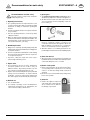
Ballast weights
Ballast weights
The tractor must be fitted with sufficient ballast weights at
the front to ensure steering and braking ability.
At least 20% of the unloaded vehicle weight
on the front axle.
Lifting Unit (Three-point Linkage)
- The tractor’s lifting unit (three-point linkage) must be
designed for the load arising. (See technical data)
- The lifting rods must be adjusted to the same length
using the corresponding adjusting device (4).
(See tractor manufacturer’s operating instructions)
- Select the rear position if the lifting rods can be adjusted
in various positions on the lower link. This relieves the
pressure on the tractor’s hydraulic system. (Safety
measures for transport journeys)
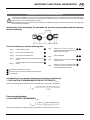
Required Hydraulic Connections
Version Consumer Hydraulic connection Marking
(Implement side)
Standard Row marker Single-action with floating position
hydraulic upper link (variation) Dual-action
Option Hydraulic coulter pressure adjustment Single-action
Required Power Connections
Version Consumer Pole Volt Power connection
Standard Lighting 7-pin 12 V DC to DIN-ISO 1724
Compass control unit 3-pin 12 V DC to DIN-ISO 9680
20%
Kg
371-08-16
371-08-16

- 13 -
1300-GB AN- UND ABBAU_8611
GB
HITCHING AND UNCOUPLING
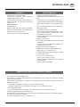
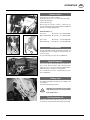
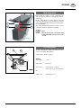
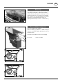
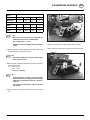
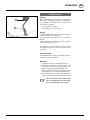
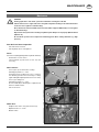
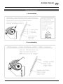
Loading
Suspend with textile straps at iron rod1.
Lift only by itself and with empty hopper (without soil-
working machine).
Ensure sufficient load bearing capacity of belts.
Handle carefully, keep balanced.
Keep clear of suspended loads.
Caution!
Do not remain
close to or under
the raised ma-
chine.
Caution!
Risk of crushing.
Stay outside the
lifting range of
the three-point
suspension when
operating the
linkage.
Caution!
Risk of crushing.
Secure the tractor
against rolling
and check the
seed drill for a
safe stand when
hitching and un-
coupling the seed
drill!
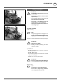
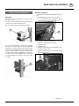
Hitching
The seed drill may be hitched directly to the tractor or to a
hydrolift of a rotary harrow.
Hitching requirements:
- Three-point connection Cat. II)
- Tractor is standing horizontal
1. Couple lower link (2)
2. Secure coupling device properly.
3. Couple upper link (3)
4. Secure coupling device properly.
5. Set the implement horizontally on upper link (3) (Arrow(7)
front left behind the reflective plate. The arrow tip must
be exactly above the droplet tip.).
6. Connect connection lines (hydraulic hose, lighting cable
(4)
7. Connect Compass terminal (5) and attach the terminal
in the tractor. (The terminal is equipped with a small
magnetic plate)
8. Lift up support leg (6) and secure
Caution!
Do not fill the hopper with seed until after
hitching to the tractor and transport!
Uncoupling
Caution!
Only park the seed drill on firm, level
ground!
Caution!
Relieve the coulter pressure completely
prior to hitching to increase the stability
of the unhitched seed drill.
- Empty the seed hopper prior to unhitching!
- Fold up seed drill track loosener
- Uncoupling in reverse order to hitching
6
2
3
4
5
7
1

- 14 -
1300-GB AN- UND ABBAU_8611
HITCHING AND UNCOUPLING GB
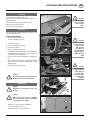
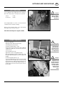
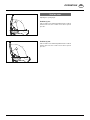
Tyres: tread/scraper
The seed drill-tyres have a high air pressure on delivery.
Before first using set tyres to the air pressure provided.
6.00-16 - 1.2 bar
10.0/75-15.5 - 0.8 bar
If the haulage width in ”eco 300” is over 3m the wheels
should therefore be rotated for haulage.
Wheel scraper (optional extra): set up appropriately
depending on tyres and wheel position.
With wheel mounting extra support needed!
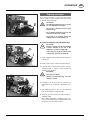
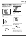
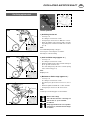
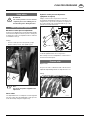
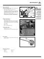
Transport Preparations
- Close the hopper lid.
- Emptying troughs folded up and locked in.
- Fold and pin up the track marker
- Fold up the tramline markers – plug.
- Put up shear protection at the perfect shutter (additional
equipment) and with ”3m” on both sides remove the
shutter element.
- Set-up shutdown protection
- Adjust tractor under steering tightly sideways
- When transporting the machine on public roads, mark
the outline with warning signs and connect lights (laut
StVZO).
- Fix harrow bar with both bolts (1,2)
- If for the VITASEM 302 the wheels were turned with
regard to the press-in depth prior to work, then they
must be returned to original position for transport. The
implement exceeds the transport width stated by us of
3m if the wheels are turned. Therefore please observe
the local laws.
Caution!
Support the raised
machine addition-
ally when attach-
ing wheels!
Safety note:
Statutory notes on
attached imple-
ments which are
towed by tractors
during road travel
- See Appendix C
Caution!
Bring both row
markers into the
transport position
and secure before
travelling on pub-
lic roads. Retract
and secure any
harrow exten-
sions!
1
2

- 15 -
1600_GB-Compass-Terminal_8611
GB
COMPASS TERMINAL
Performance features of the terminal
Connection to power
The terminal’s electricity is supplied via a plug connection (in accordance with DIN 9680) to the tractor’s 12 V on-board
electrical system,. These three-pin plugs may also be two-pin versions as only two main wires (+12 V, ground) are required.
Be advised!
Other plug and socket designs are not permitted otherwise functional reliability cannot be guaranteed.
Technical data
Operating voltage: +10V ...... +15V
Operating temperature range: -20°C +60°C
Storage temperature: -30°C +70°C
Degree of protection: IP65
Fuse: 15A fuse in operating voltage plug.
LCD display: backlit
Be advised!
The terminal is to be protected from the wet and the cold! The terminal is not intended for storage
outside!
Usable functions
The Compass terminal is a compact on-board computer with many useful functions. It performs important control and
monitoring tasks and makes your work easier with display and auxiliary functions.
Overview of usable functions:
Control functions:
- Setting tramlines
- Additional setting of tramline marking
- Manual or automatic switching of the drive-through counter e.g. by means of the track marker shuttle valve, signal
socket or tailwheel sensor or transmission signal
- Interruption of the automatic switching of the drive-through counter (when driving around obstacles)
- Regulating the Spread rate (optional extra)
Display functions:
- Through-drive counter and tramline cycle display
- Part area hectare counter
- Total area hectare counter
- Driving speed
- Sowing shaft speed
- Current distribution rate
Monitoring functions:
- Sowing shaft monitoring
- Fill level monitoring
Auxiliary functions:
- Sensor test
- Calibration aid to calculate and count the number of crank turns
- Adjustable delay for the automatic switching of the drive-through counter
- Optional menu guide in several languages

- 16 -
1600_GB-Compass-Terminal_8611
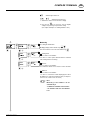
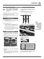
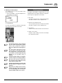
COMPASS TERMINAL GB
Display driving speed (a)
Press once = Display driving speed (in km/h)
a Driving speed (in km/h
b Tramline symbol: A tramline is being set up if the tramline symbol is displayed.
Display hectare counter (5)
press 1x = display daily hectare counter
press 2x = display yearly hectare counter (designated with the mark "∑")
press 3x = total counter (not deletable, recognisable by the black background of the
number)
delete daily or yearly hectare counter = press for 3 seconds resp. until you hear
the signal tone
a Hectare counter
b Tramline symbol: A tramline is being set up if the tramline symbol is displayed.
Displayrotations (8)
Press once = display sowing shaft speeds (in rpm)
Initial operation
The Compass terminal is switched on with the key. The set machine type and software version appear in the display
for approx. 3 seconds, then the speed display appears.
The Compass terminal is switched off with the key (depress for 3 seconds).
Before initial operation, check and adapt the correct basic setting (machine type, language, ..).
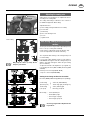
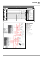
COMPASS terminal
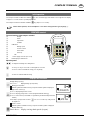
The user interface of the Compass terminal
(0) Display
(1) Menu
(2) Spread rate
(3) Tramline
(4) Calibration
(5) Driving speed
(6) Hectare counter
(7) Arrow down
(8) Arrow up
(9) I/O
(A) Power supply connector (fuse 15 A)
(B) Parallel plug for data transfer
Operating notes
To navigate and change the setting values
To save, press key for 2 seconds or until signal tone is heard.
To move to a menu level without saving, press key briefly
To leave the submenu without saving
Displays and functions
0,0 km/h
a
b
0,23 ha
a
b
0
123
654
789
AB

- 17 -
1600_GB-Compass-Terminal_8611
COMPASS TERMINAL GB
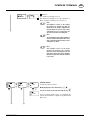
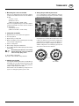
Display Tramline step and drive-through counter (7)
press 1x = current tramline step and drive-through counter.
a Tramline type and tramline step
b Symbol flashes when the driving speed is detected.
Note:
If the symbol does not appear, this indicates a defect.
The power-train and/or sensors are to be checked.
c Drive-through counter: counts the line passing-throughs automatically as soon
as the implement is set down from headland position. In the Settings menu you
can select from 4 options based on which these will be switched on.
d The field symbol indicates where work commenced on the field.
Start work left/ Start work right
e Display "Tramline is being set up!" This notification is displayed when a tramline
is supposed to be created during a line passing-through.
Note:
The notification "Tramline is being set up!" appears immediately
after switching on the drive-through counter.
The creation of the tramline as such begins only when the speed
has exceeded 1 km/h.
Operation:
Tramline tact can be changed manually using the arrow keys .
Key
Press for 2 secs.
=
The drive-through counter is reset to start value 1.
Press twice = STOP appears on the screen; counting is paused and the current value is saved (e.g. avoid
an obstacle). Press again = counting restarts with the saved value.
Displayspread rate (6)
Press once = Displays the set spread rate and gear setting (prerequisite: the
calibration was performed)
a current spread rate
b Spread rate in percentage of the calibrated value
c Gear setting
d Display: "Tramline is being set up!"
Optional equipment: electrical seed setting
The seed amount can be changed with a pre-set increment (%) using the arrow
keys .
Repeated actuation of keys is possible.
The spread rate values and the gear setting are updated automatically.
Note:
The minimum spread rate increment is 0.1 kg/ha. Because
the spread rate is rounded, it is possible that for low spread
rates you arrive at step changes (%) due to rounding.
The increment (%) can be set in the Settings menu - Seed.
Saatmengen-
verstellung
240,0 kg/ha
Saatmengen-
verstellung
100% G:77
a
bc
d
asym. 8
akt. 1
a
bc
d
asym. 8
akt. 1
e
110%

- 18 -
1600_GB-Compass-Terminal_8611
COMPASS TERMINAL GB
The crank symbol on the display shows the number of times the crank must be turned to set the new gear setting!
If the spread rate is not equal with the nominal value set at calibration (=100%), when you start off, you will see an indi-
cation for about 3 seconds that signals the modified spread rate. The indication appears every time when you start the
engine and shows the percent value of the nominal spread rate with which you sow at the moment.
To turn off the indication, reset the spread rate to 100% with the help of the arrow keys.

- 19 -
1600_GB-Compass-Terminal_8611
COMPASS TERMINAL GB
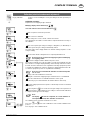
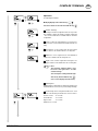
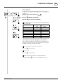
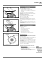
Calibration sequence
Requirement: The emptying trough is attached.
Modifying display values with the keys
Save and continue to the next menu with the key
a Input of required seed amount per hectare
b Input of area to be calibrated
Seed quantity per hectare Area to be calibrated
< 30 kg 1/10 ha
30 kg - 70 kg 1/20 ha
70 kg - 250 kg 1/40 ha
> 250 kg 1/100ha
This setting affects the number of crank rotations required and thus the accuracy of the
calibration. The table above is a recommendation, so as not to affect the precision of the test.
c Gear setting
1. Adjust the gear lever according to sowing table (see Attachment)
2. Input the gear lever setting in the control system.
d Turn the crank until the sowing wheels are completely filled with seed
Note: Remove any seed from the emptying trough to avoid distorting
the weighing.
e Turn the crank the number of times shown
The Compass terminal now counts the number of crank turns backwards from the value
shown. In doing this the display will always show how many crank turns are still to be
made. The last 5 crank turns are also signalled acoustically to prepare the operator for
the completion of calibration A continuous signal tone is triggered when the value <0> is
reached to prompt the operator to stop calibration immediately.
Note: Rotate the crank slowly and regularly (about 1 sec per rotation),
so as not to affect the precision of the test.
Note: Inaccuracies from manual calibrations are automatically taken
into account.
f Display of theoretical calibrated seed amount
Weighing the seed from the emptying trough = actual amount of seed distributed
g Enter the actual amount of seed distributed in the control system
(if the arrow key is pressed and held, then the number increases faster)
h The gear setting required for the respective seed amount per hectare is calculated
and displayed. This value is to be set at the gear lever of the seed drill
The calibration can be repeated several times as a check.
Press key at the end of calibration in order to repeat the e "Turning" process.
Press any other key (except and ) to leave the calibration mode.
Calibration (standard)
Key (4) calibration: Sequence control for finding the correct gear setting for an exact spread rate
per hectare
a
b
c
d
e
f
g
h

- 20 -
1600_GB-Compass-Terminal_8611
COMPASS TERMINAL GB
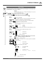
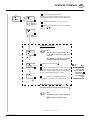
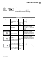
Calibration sequence
Requirement: The emptying trough is attached.
Modifying display values with the keys
Save and continue to the next menu with the key
a Input of required seed amount per hectare
a Input of area to be calibrated
Possible settings are: 1/10 ha, 1/20 ha, 1/40 ha and 1/100 ha
This setting affects the number of crank rotations required and thus the accuracy of
the calibration.
a Input of the required gear setting according to sowing table (see Attachment) in
the control system The gear setting is automatically started.
The crank symbol in the display indicates the manual cranking required to set the
new gear setting!
d Turn the crank until the sowing wheels are completely filled with seed.
Note: Remove any seed from the emptying trough to avoid falsifying
the weighing results.
e Set back the displayed rotations with the help of the crank.
The Compass terminal now counts the number of crank turns backwards from the
value shown. In so doing the display will always show how many crank turns are still to
be made. The last 5 crank turns are also signalled acoustically to prompt the operator
to complete the calibration. A continuous signal tone is triggered when the value <0>
is reached to prompt the operator to stop calibration immediately.
Note: Inaccuracies with manual calibration are automatically taken
into account.
f Display of theoretical calibrated seed amount
Weighing the seed from the emptying trough = actual amount of seed distributed
g Enter the actual amount of seed distributed into the control system
(if an arrow key is pressed and held then the number advance starts faster)
h The gear setting required for the respective seed amount per hectare is calculated
and displayed.
i By pressing the key for 2 seconds, the new gear setting for the required seed
amount per hectare is started. When the gear setting is reached and the calibration
is completed, "End" appears in the display.
Note:
The display i indicates the completed, successful calibration. If
interrupted beforehand, then calibration is ineffective!
The calibration can be repeated several times as a check.
Press keys and at the end of calibration to start a further calibration from
point "e".
Press any key to leave calibration mode.
Calibration (electrical seed amount adjustment)
Key (4) calibration: Sequence control for finding the correct gear setting for an exact spread rate per
hectare
a
b
c
d
e
f
g
h
2 secs.
i
Page is loading ...
Page is loading ...
Page is loading ...
Page is loading ...
Page is loading ...
Page is loading ...
Page is loading ...
Page is loading ...
Page is loading ...
Page is loading ...
Page is loading ...
Page is loading ...
Page is loading ...
Page is loading ...
Page is loading ...
Page is loading ...
Page is loading ...
Page is loading ...
Page is loading ...
Page is loading ...
Page is loading ...
Page is loading ...
Page is loading ...
Page is loading ...
Page is loading ...
Page is loading ...
Page is loading ...
Page is loading ...
Page is loading ...
Page is loading ...
Page is loading ...
Page is loading ...
Page is loading ...
Page is loading ...
Page is loading ...
Page is loading ...
Page is loading ...
Page is loading ...
Page is loading ...
Page is loading ...
Page is loading ...
Page is loading ...
Page is loading ...
Page is loading ...
Page is loading ...
Page is loading ...
Page is loading ...
Page is loading ...
Page is loading ...
Page is loading ...
Page is loading ...
Page is loading ...
Page is loading ...
Page is loading ...
Page is loading ...
Page is loading ...
Page is loading ...
Page is loading ...
Page is loading ...
Page is loading ...
Page is loading ...
Page is loading ...
Page is loading ...
Page is loading ...
Page is loading ...
Page is loading ...
Page is loading ...
Page is loading ...
Page is loading ...
Page is loading ...
Page is loading ...
Page is loading ...
-
 1
1
-
 2
2
-
 3
3
-
 4
4
-
 5
5
-
 6
6
-
 7
7
-
 8
8
-
 9
9
-
 10
10
-
 11
11
-
 12
12
-
 13
13
-
 14
14
-
 15
15
-
 16
16
-
 17
17
-
 18
18
-
 19
19
-
 20
20
-
 21
21
-
 22
22
-
 23
23
-
 24
24
-
 25
25
-
 26
26
-
 27
27
-
 28
28
-
 29
29
-
 30
30
-
 31
31
-
 32
32
-
 33
33
-
 34
34
-
 35
35
-
 36
36
-
 37
37
-
 38
38
-
 39
39
-
 40
40
-
 41
41
-
 42
42
-
 43
43
-
 44
44
-
 45
45
-
 46
46
-
 47
47
-
 48
48
-
 49
49
-
 50
50
-
 51
51
-
 52
52
-
 53
53
-
 54
54
-
 55
55
-
 56
56
-
 57
57
-
 58
58
-
 59
59
-
 60
60
-
 61
61
-
 62
62
-
 63
63
-
 64
64
-
 65
65
-
 66
66
-
 67
67
-
 68
68
-
 69
69
-
 70
70
-
 71
71
-
 72
72
-
 73
73
-
 74
74
-
 75
75
-
 76
76
-
 77
77
-
 78
78
-
 79
79
-
 80
80
-
 81
81
-
 82
82
-
 83
83
-
 84
84
-
 85
85
-
 86
86
-
 87
87
-
 88
88
-
 89
89
-
 90
90
-
 91
91
-
 92
92


Pottinger VITASEM 252 Operating instructions
- Category
- Kitchen & houseware accessories
- Type
- Operating instructions
- This manual is also suitable for
Ask a question and I''ll find the answer in the document
Finding information in a document is now easier with AI
Related papers
-
Pottinger VITASEM302ADD Operating instructions
-
-
-
-
-
-
-
-
-
Other documents
-
 Tume Draco 4000 User manual
-
 Amazone ED01 Owner's manual
-
 Amazone AD 3000 Super Classic Line Operating instructions
-
Armitage Shanks S0752 Installation guide
-
horsch FOCUS ST Operating Instructions Manual
-
 Amazone Cataya 3000 Super Operating instructions
-
 Amazone ED 452 Owner's manual
-
 Tume JC 4000 Star User manual
-
 Tume Titan 3000 User manual
-
 Amazone PRIMERA DMC 6000-2/-2C ISOBUS Operating instructions


