Page is loading ...

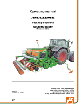
Operating manual
az
Pack top seed drill
Cataya 3000 / 4000 Super
MG6519
BAH0105-1 02.20
Please read and observe this
operating manual before initial
operation of the implement!
Keep it in a safe place for future use!
en

2 Cataya Super BAH0105-1 02.20

Cataya Super BAH0105-1 02.20 3
Identification data
Please insert the identification data of the implement. The identifica-
tion data are arranged on the rating plate.
Implement number (ten digits):
Type:
Year of manufacture:
Permissible total weight [kg]:
Manufacturer address
AMAZONEN-WERKE
H. DREYER GmbH & Co. KG
Postfach 51
D-49202
Tel.:
Email:
Hasbergen, Germany
+ 49 (0) 5405 50 1-0
Spare Parts Order
Spare parts lists are freely accessible in the spare parts portal at
www.amazone.de.
Please send orders to your AMAZONE dealer.
Formalities of the operating manual
Type: Cataya Super
Document number: MG6519
Compilation date: 02.20
Copyright AMAZONEN-WERKE H. DREYER GmbH & Co. KG, 2020
All rights reserved.
Reprinting, even of sections, permitted only with the approval of
AMAZONEN-WERKE H. DREYER GmbH & Co. KG.

4 Cataya Super BAH0105-1 02.20
Foreword
Dear Customer,
You have chosen one of the quality products from the wide product range of AMAZONEN-WERKE,
H. DREYER GmbH & Co. KG. We thank you for your trust in our products.
On receiving the implement, check to see if it has been damaged during transport or if parts are miss-
ing. Using the delivery note, check that the implement has been delivered in full, including any special
equipment ordered. Damage can only be rectified if problems are claimed immediately.
Before initial operation, read and comply with the information in this operating manual, and particularly
the safety instructions. Only after careful reading will you be able to benefit from the full scope of your
newly purchased implement.
Please ensure that all the implement operators have read this operating manual before they put the
implement into operation.
Should you have any questions or problems, please consult this operating manual or contact your
local service partner.
Regular maintenance and timely replacement of worn or damaged parts increases the service life of
your implement.

User information
Cataya Super BAH0105-1 02.20 5
1User information ........................................................................................ 10
2General Safety Instructions ...................................................................... 11
2.1Obligations and liability .......................................................................................................... 11
2.2Representation of safety symbols .......................................................................................... 13
2.3Organisational measures ....................................................................................................... 14
2.4Safety and protective equipment ........................................................................................... 14
2.5Informal safety measures ....................................................................................................... 14
2.6User training ........................................................................................................................... 15
2.7Safety measures in normal operation .................................................................................... 16
2.8Danger from residual energy ................................................................................................. 16
2.9Maintenance and repair work, fault elimination ..................................................................... 16
2.10Design changes ..................................................................................................................... 16
2.10.1Spare and wear parts and aids .............................................................................................. 17
2.11Cleaning and disposal ............................................................................................................ 17
2.12Workstation of the operator .................................................................................................... 17
2.13Warning symbols on the implement ....................................................................................... 18
2.13.1Position of warning symbols .................................................................................................. 2 4
2.14Dangers in case of non-compliance with the safety instructions ........................................... 25
2.15Safety-conscious working ...................................................................................................... 25
2.16Safety information for users ................................................................................................... 26
2.16.1General safety instructions and accident prevention instructions .......................................... 26
2.16.2Hydraulic system .................................................................................................................... 30
2.16.3Electrical system .................................................................................................................... 31
2.16.4Mounted implements .............................................................................................................. 32
2.16.5Operation of the seed drill ...................................................................................................... 33
2.16.6Cleaning, maintenance and repair ......................................................................................... 33
3Loading and unloading the implement upon delivery ............................ 34
4Product description ................................................................................... 36
4.1Components of the AMAZONE seeding combination ........................................................... 36
4.2Equipment variations of the Cataya pack top seed drill ......................................................... 37
4.3Assembly groups of the Cataya pack top seed drill ............................................................... 39
4.4Safety and protective equipment ........................................................................................... 41
4.5Overview – Supply cable / hydraulic hose lines ..................................................................... 42
4.5.1Supply cable........................................................................................................................... 42
4.5.2Identification of the hydraulic hose lines ................................................................................ 42
4.5.3Connection and function of the tractor control units .............................................................. 43
4.5.4Comfort hydraulic system - Implements with ISOBUS system .............................................. 44
4.6Traffic safety equipment ......................................................................................................... 45
4.7Proper use .............................................................................................................................. 4 6
4.7.1Approved AMAZONE implement combinations ..................................................................... 47
4.8Danger areas and danger points ........................................................................................... 48
4.9Rating plate and CE mark ...................................................................................................... 49
4.10Technical data ........................................................................................................................ 50
4.11Noise production data ............................................................................................................ 50
4.11.1Technical data for calculating the tractor weight and the tractor axle loads .......................... 51
4.12Tractor equipment .................................................................................................................. 52
4.13Operating pressure of the hydraulic system .......................................................................... 52
5Structure and function .............................................................................. 53
5.1AMAZONE AmaDrill 2 control terminal .................................................................................. 56
5.2AMAZONE calibration button ................................................................................................. 56
5.3Control terminal for implements with ISOBUS system .......................................................... 57
5.3.1AMAZONE AmaTron 4 control terminal ................................................................................. 57

User information
6 Cataya Super BAH0105-1 02.20
5.4AMAZONE TwinTerminal ...................................................................................................... 57
5.5Implement documentation ..................................................................................................... 58
5.6Central key ............................................................................................................................ 58
5.7Hand wash tank ..................................................................................................................... 58
5.8Radar device ......................................................................................................................... 59
5.9Seed hopper and loading board ............................................................................................ 60
5.9.1Fill level monitoring ................................................................................................................ 61
5.10Seeding shaft drive................................................................................................................ 61
5.11Metering ................................................................................................................................ 62
5.11.1Setting values ........................................................................................................................ 64
5.11.1.1Coarse and fine metering wheel ........................................................................................... 66
5.11.1.2Bean metering wheel............................................................................................................. 66
5.11.1.3Bottom flaps .......................................................................................................................... 67
5.11.1.4Slide gate .............................................................................................................................. 68
5.11.1.5Agitator shaft support ............................................................................................................ 68
5.12Seed rate calibration ............................................................................................................. 69
5.12.1Calibration - Implements with electric seeding shaft drive .................................................... 72
5.13RoTeC Control coulter .......................................................................................................... 73
5.14TwinTeC double disc coulter ................................................................................................. 75
5.14.1Seed placement depth (TwinTeC) ........................................................................................ 77
5.15Coulter pressure, seed rate increase and coulter lift (all coulter types) ................................ 78
5.15.1Coulter pressure / coulter lift (manually actuated) ................................................................ 78
5.15.2Coulter pressure, seed rate increase and coulter lift (all coulter types -
hydraulically actuated) .......................................................................................................... 79
5.15.2.1Coulter pressure (hydraulically actuated) ............................................................................. 79
5.15.2.2Activating the automatic seed rate increase ......................................................................... 80
5.15.2.3Soil tillage without seeding (coulter lift) ................................................................................. 81
5.16Exact following harrow .......................................................................................................... 82
5.16.1Exact following harrow tine position ...................................................................................... 83
5.16.2Exact following harrow pressure ........................................................................................... 85
5.16.3Seeding without exact following harrow ................................................................................ 86
5.17Roller harrow ......................................................................................................................... 87
5.18Tramlines ............................................................................................................................... 89
5.18.1Tramline rhythm, tabular determination ................................................................................ 92
5.18.2Tramline rhythm, graphic determination................................................................................ 92
5.19One-sided switching .............................................................................................................. 94
5.19.1One-sided switching – One-sided seeding shaft drive .......................................................... 94
5.19.2One-sided switching – seeding shaft drive on both sides ..................................................... 95
5.20Tramline marker .................................................................................................................... 96
5.21Track marker ......................................................................................................................... 97
5.22Work floodlights ..................................................................................................................... 98
5.23Coulter array lighting ............................................................................................................. 98
5.24Camera system ..................................................................................................................... 98
5.25GreenDrill 200E ..................................................................................................................... 99
6Initial operation ........................................................................................ 100
6.1Checking the suitability of the tractor .................................................................................. 101
6.1.1Calculating the actual values for the total tractor weight, tractor axle loads and tyre
load-bearing capacity, as well as the required minimum ballast weight ............................. 102
6.1.1.1Data required for the calculation (attached implement) ...................................................... 103
6.1.1.2Calculation of the required minimum ballast weight at the front GV min of the tractor
to ensure steering capability ............................................................................................... 104
6.1.1.3Calculation of the actual front axle load of the tractor TV tat ................................................. 104
6.1.1.4Calculation of the actual total weight of the combined tractor and implement .................... 104
6.1.1.5Calculation of the actual rear axle load of the tractor TH tat ................................................. 104
6.1.1.6Load-bearing capacity of the tractor tyres ........................................................................... 104
6.1.1.7Table ................................................................................................................................... 105
6.2Secure the tractor / implement against unintentional starting and rolling away ................. 106

User information
Cataya Super BAH0105-1 02.20 7
7Coupling and uncoupling the implement .............................................. 107
7.1Hydraulic hose lines ............................................................................................................. 109
7.1.1Coupling the hydraulic hose lines ........................................................................................ 109
7.1.2Disconnecting the hydraulic hose lines ................................................................................ 110
7.2Coupling and uncoupling implements .................................................................................. 111
7.2.1Coupling - Tractor and soil tillage implement ....................................................................... 113
7.3Coupling - Pack top seed drill and soil tillage implement .................................................... 114
7.3.1Uncoupling – Combination from the tractor ......................................................................... 118
7.3.2Uncoupling – Soil tillage implement and pack top seed drill ................................................ 119
7.4Checking the tramline track width ........................................................................................ 123
7.5Checking the tramline wheelmark width .............................................................................. 123
8Settings ..................................................................................................... 124
8.1Folding the steps up and down ............................................................................................ 125
8.2Fill the seed hopper ............................................................................................................. 127
8.3Setting the seed rate ............................................................................................................ 131
8.3.1Bottom flap position ............................................................................................................. 131
8.3.2Sliding shutter position ......................................................................................................... 132
8.3.3Agitator shaft support ........................................................................................................... 133
8.3.3.1Seeding with agitator shaft support ..................................................................................... 133
8.3.3.2Seeding without agitator shaft support ................................................................................ 133
8.4Calibrating the seed rate ...................................................................................................... 134
8.5RoTeC Control coulter ......................................................................................................... 137
8.5.1Adjusting and checking the seed placement depth ............................................................. 137
8.5.1.1Adjusting the depth control discs / wheels ........................................................................... 138
8.6TwinTeC double disc coulter ................................................................................................ 140
8.6.1Adjusting and checking the seed placement depth ............................................................. 140
8.6.2Adjusting the TwinTeC harrow tines .................................................................................... 141
8.7Coulter pressure, seed rate increase and coulter lift ........................................................... 144
8.7.1Coulter pressure / coulter lift (manually actuated) ............................................................... 144
8.7.2Coulter pressure, seed rate increase and coulter lift (all coulter types -
hydraulically actuated) ......................................................................................................... 145
8.7.2.1Increasing / reducing the coulter pressure ........................................................................... 146
8.7.2.2Adjusting the seed rate increase ......................................................................................... 146
8.7.2.3Soil tillage without seeding (coulter lift) ................................................................................ 147
8.8Adjusting the exact following harrow ................................................................................... 148
8.8.1Infinitely adjustable exact following harrow tines ................................................................. 148
8.8.2Setting the exact following harrow pressure ........................................................................ 149
8.8.3Moving the exact following harrow to the working/transport position .................................. 150
8.8.3.1Move the exact following harrow into working position ........................................................ 150
8.8.3.2Moving the exact following harrow into transport position ................................................... 150
8.8.4Seeding without exact following harrow (exact following harrow lift) ................................... 150
8.9Adjusting the roller harrow ................................................................................................... 151
8.9.1Roller harrow tines - Adjusting the pitch .............................................................................. 151
8.9.2Roller harrow tines - Adjusting the working depth ............................................................... 151
8.9.3Setting the roller contact pressure ....................................................................................... 152
8.10Moving the track marker to the working / transport position ................................................ 153
8.11One-sided switching ............................................................................................................. 154
8.11.1One-sided switching - Implement with one seeding shaft drive motor ................................ 154
8.11.2One-sided switching on seed drills with two seeding shaft drive motors ............................. 155
8.12Moving the tramline marker into working/transport position ................................................ 156
8.12.1Move the tramline marker to working position ..................................................................... 156
8.12.2Move the tramline markers to the transport position............................................................ 157
8.13Moving the exact following harrow road safety bar into road transport/parking
position ................................................................................................................................. 158
8.13.1Moving the road safety bar into road transport position ...................................................... 158
8.13.2Moving the road safety bar into parking position ................................................................. 158
9Transportation ......................................................................................... 159

User information
8 Cataya Super BAH0105-1 02.20
9.1Moving the seeding combination into transport position ..................................................... 159
9.2Legal regulations and safety ............................................................................................... 160
10Use of the implement .............................................................................. 164
10.1Initial operation .................................................................................................................... 165
10.2Work floodlights ................................................................................................................... 165
10.3Coulter array lighting ........................................................................................................... 166
10.4Moving the implement from transport into working position ................................................ 166
10.5Work commencement ......................................................................................................... 166
10.6During operation .................................................................................................................. 168
10.6.1Overview of checks during operation .................................................................................. 168
10.6.2Turning at end of the field ................................................................................................... 169
10.6.3Track marker ....................................................................................................................... 170
10.6.4End of work on the field ....................................................................................................... 170
10.7Emptying the seed hopper and seed housing ..................................................................... 171
11Faults ........................................................................................................ 175
11.1Residual seed quantity display ............................................................................................ 176
11.2Deviations between the set and actual seed rate ............................................................... 176
12Maintenance and repairs ........................................................................ 177
12.1Maintenance schedule ........................................................................................................ 177
12.2Lubrication schedule ........................................................................................................... 178
12.2.1Lubrication points ................................................................................................................ 178
12.3Safety .................................................................................................................................. 179
12.3.1Safety when cleaning the implement .................................................................................. 180
12.3.2Safety when working on the hydraulic system .................................................................... 181
12.4Opening the protective equipment ...................................................................................... 182
12.4.1Open the function flap ......................................................................................................... 182
12.4.2Opening the cover ............................................................................................................... 183
12.5Installations ......................................................................................................................... 184
12.5.1Shutdown of the implement over a long period of time ....................................................... 184
12.5.2Adjusting the tramline control .............................................................................................. 185
12.5.2.1Folding down the lay shaft .................................................................................................. 187
12.5.2.2Folding up the lay shaft ....................................................................................................... 188
12.5.2.3Setting the tramline track width ........................................................................................... 189
12.5.2.4Setting the tramline wheelmark width ................................................................................. 190
12.5.2.5Conversion of a metering wheel to a tramline metering wheel ........................................... 191
12.5.2.6Conversion of a tramline metering wheel to a metering wheel ........................................... 193
12.5.2.7Conversion of a tramline metering wheel to a metering wheel by shifting the gear
wheel on the lay shaft ......................................................................................................... 193
12.5.2.8Conversion of a tramline metering wheel to a metering wheel by removing the gear
wheel pairing from the lay shaft and seeding shaft ............................................................. 194
12.5.3Changing the metering wheel ............................................................................................. 195
12.5.3.1Removing the seeding shaft half that is driven via the coupling ......................................... 197
12.5.3.2Removing the seeding shaft half that is driven by the electric motor .................................. 198
12.6Maintenance ........................................................................................................................ 201
12.6.1Visual inspection of the upper and lower link pins .............................................................. 201
12.6.2Visual check of the hydraulic hose lines and couplings ...................................................... 202
12.6.2.1Date of manufacture of the hydraulic hose line ................................................................... 202
12.6.3Check the chain tension ...................................................................................................... 203
12.6.4Bottom flaps, check basic position ...................................................................................... 204
12.6.5Checking / readjusting / replacing the TwinTeC roller scraper ........................................... 205
12.7Repairs (specialist workshop work) ..................................................................................... 206
12.7.1Checking the hydraulic hose lines ....................................................................................... 206
12.7.1.1Safety when working on hydraulic hose lines ..................................................................... 207
12.7.2Checking and readjusting the TwinTeC disc bearings ........................................................ 208
12.7.2.1Checking the TwinTeC disc bearings .................................................................................. 208
12.7.2.2Readjusting the TwinTeC disc bearings ............................................................................. 208
12.7.3Checking / replacing the TwinTeC inner scraper ................................................................ 210

User information
Cataya Super BAH0105-1 02.20 9
12.7.4Checking / replacing the TwinTeC baffle lip ........................................................................ 211
12.7.4.1Installation instruction: Removing the TwinTeC seed line ................................................... 212
12.7.5Checking / replacing the TwinTeC press roller .................................................................... 213
12.8Oils and greases .................................................................................................................. 214
12.8.1Lubricants for grease nipples and grease guns ................................................................... 214
12.9Bolt tightening torques ......................................................................................................... 215
13Hydraulic diagram .................................................................................... 216
13.1Hydraulic diagram Cataya 3000/4000 Super ....................................................................... 216
13.2Hydraulic diagram Cataya 3/4000 Super with Comfort hydraulic system ........................... 218

User information
10 Cataya Super BAH0105-1 02.20
1 User information
The User information section provides information concerning the operating manual.
This operating manual is valid for all versions of the implement.
Figures serve as a reference and are to be understood as representations of the principle.
All of the equipment is described without indicating it as special equipment. A description may be pro-
vided for equipment that is not fitted on the implement or is only available in certain markets. The sales
documents provide information on the equipment of your implement or consult your service partner for
more detailed information.
All information in this operating manual corresponds to the state of knowledge at the time of publica-
tion. Due to ongoing development of the implement, deviations are possible between the implement
and the information in this operating manual. No claims can be made based on differences in the
specifications, figures or descriptions.
If you want to sell the implement, ensure that the operating manual is supplied with the implement.
The operating manual
describes the operation and maintenance of the implement
provides important information on safe and efficient handling of the implement
is an integral part of the implement and should always be kept with the implement or the towing
vehicle
must be kept in a safe place for future use.
Activities to be carried out by the user are presented as numbered instructions. Always observe the
sequence of the instructions. The reaction to instructions is given by an arrow. Example:
1. Instruction 1
Reaction of the implement to handling instruction 1
2. Instruction 2
Listings without a mandatory sequence are presented as a listing with bullets.
Example: Point 1
Point 2
Numbers in round brackets refer to the item numbers in the illustrations. The first number refers to the
diagram and the second number to the item.
Example: (Fig. 3/6) = Figure 3 / Position 6
All the directions specified in the operating manual are always viewed in the direction of travel.

General Safety Instructions
Cataya Super BAH0105-1 02.20 11
2 General Safety Instructions
This section contains important information on safe operation of the
implement.
2.1 Obligations and liability
Comply with the instructions in the operating manual
Knowledge of the basic safety information and safety regulations is a
basic requirement for safe handling and fault-free implement opera-
tion.
Obligations of the operator
The operator is obliged only to let those people work with/on the im-
plement who
are aware of the basic workplace safety information and accident
prevention regulations
have been trained in working with/on the implement
have read and understood this operating manual.
The operator is obliged
to keep all the warning symbols on the implement in a legible
state
to replace damaged warning symbols.
Obligations of the user
Before starting work, anyone charged with working with/on the ma-
chine is obliged
to comply with the basic workplace safety instructions and acci-
dent prevention regulations
to read and understand the "General safety information" section
of this operating manual
to read the section "Warning symbols and other labels on the
implement" in this operating manual and to follow the safety in-
structions represented by the warning symbols when operating
the implement
to get to know the implement
to read the sections of this operating manual, important for carry-
ing out your work.
If the user discovers that a function is not working properly, then they
must eliminate this fault immediately. If this is not the task of the user
or if the user does not have the appropriate technical knowledge, then
they should report this fault to their superior (operator).

General Safety Instructions
12 Cataya Super BAH0105-1 02.20
Risks in handling the implement
The implement has been constructed to the state-of-the art and the
recognised rules of safety. However, operating the implement may
cause risks and restrictions
the health and safety of the user or third persons
the implement itself
other property.
Only use the implement
for the purpose for which it was intended
in a perfect state of repair.
Eliminate any faults immediately which could impair safety.
Guarantee and liability
Our "General conditions of sales and delivery" are always applicable.
These shall be available to the operator, at the latest on conclusion of
the contract. Guarantee and liability claims for damage to people or
property will be excluded if they can be traced back to one or more of
the following causes:
Improper use of the implement
Improper installation, commissioning, operation and mainte-
nance of the implement
Operation of the implement with defective safety equipment or
improperly attached or non-functioning safety and protective
equipment
Non-compliance with the instructions in the operating manual
regarding commissioning, operation and maintenance
Unauthorised design changes to the implement
Insufficient monitoring of implement parts which are subject to
wear
Improperly executed repairs
Disasters due to the effects of foreign objects and force majeure.

General Safety Instructions
Cataya Super BAH0105-1 02.20 13
2.2 Representation of safety symbols
Safety instructions are indicated by the triangular safety symbol and the highlighted signal word. The
signal word (DANGER, WARNING, CAUTION) describes the severity of the risk, and carries the fol-
lowing meaning:
DANGER
Indicates an immediate hazard with high risk, which will result in death
or serious bodily harm (loss of limbs or long-term harm), if it is not
avoided.
If the instructions are not followed, then this will result in immediate
death or serious physical injury.
WARNING
Indicates a medium risk, which could result in death or (serious) phys-
ical injury if not avoided.
If the instructions are not followed, then this may result in death or
serious physical injury.
CAUTION
Indicates a low risk which could cause minor or medium level physical
injury or damage to property if not avoided.
IMPORTANT
Indicates an obligation to special behaviour or an activity required for
proper implement handling.
Non-compliance with these instructions can cause faults on the im-
plement or disturbance to the environment.
NOTICE
Indicates handling tips and particularly useful information.
These instructions will help you to use all the functions of your imple-
ment in the best way possible.

General Safety Instructions
14 Cataya Super BAH0105-1 02.20
2.3 Organisational measures
The operator must provide the necessary personal protective equipment as per the information pro-
vided by the manufacturer of the crop protection agent to be used, such as:
Safety glasses
Protective shoes
Chemical-resistant overalls
Skin protection agents, etc.
The operating manual
must always be kept at the place at which the implement is op-
erated
must always be easily accessible for the user and maintenance
personnel.
Check all the available safety equipment regularly.
2.4 Safety and protective equipment
Before starting up the implement each time, all the safety and protection equipment must be properly
attached and fully functional. Check all safety and protection equipment regularly.
Faulty safety equipment
Faulty or disassembled safety and protection equipment can lead to dangerous situations.
2.5 Informal safety measures
As well as all the safety information in this operating manual, comply with the general, national regula-
tions pertaining to accident prevention and environmental protection.
When driving on public roads and routes you should comply with the statutory road traffic regulations.

General Safety Instructions
Cataya Super BAH0105-1 02.20 15
2.6 User training
Only those people who have been trained and instructed may work with/on the implement. The opera-
tor must clearly specify the responsibilities of the people charged with operation and maintenance
work.
People being trained may only work with/on the implement under the supervision of an experienced
person.
Person
Activity
Person specially
trained for the
activity 1)
Trained opera-
tor 2)
Persons with
specialist
training (specialist
workshop) 3)
Loading/Transport X X X
Initial operation X
Set-up, tool installation X
operation X
Maintenance X
Troubleshooting and fault elimi-
nation
X X
Disposal X
Key: X..permitted ..not permitted
1) A person who can assume a specific task and who can carry out this task for an appropriately
qualified company.
2) Instructed persons are those who have been instructed in their assigned tasks and in the possi-
ble risks in the case of improper behaviour, have been trained if necessary, and have been in-
formed about the necessary protective equipment and measures.
3) Persons with specialised technical training shall be considered as a specialist. Due to their spe-
cialist training and their knowledge of the appropriate regulations, they can evaluate the work with
which they have been charged and detect possible dangers.
Comment:
A qualification equivalent to specialist training can be obtained from several years' experience in
the relevant field.
Only a specialist workshop may carry out maintenance and repair
work on the implement, if such work is additionally marked "Work-
shop". The personnel of a specialist workshop shall possess the ap-
propriate knowledge and suitable aids (tools, lifting and support
equipment) for carrying out the maintenance and repair work on the
implement in a way which is both appropriate and safe.

General Safety Instructions
16 Cataya Super BAH0105-1 02.20
2.7 Safety measures in normal operation
Only operate the implement if all the safety and protection equipment is fully functional.
Check the implement at least once a day for visible damage and check the function of the safety and
protection equipment.
2.8 Danger from residual energy
Note that there may be residual mechanical, hydraulic, pneumatic and electrical/electronic energy on the
implement.
Use appropriate measures to inform the operator. You can find detailed information in the relevant
sections of this operating manual.
2.9 Maintenance and repair work, fault elimination
Carry out prescribed setting, maintenance and inspection work in good time.
Secure all media such as compressed air and the hydraulic system against unintentional start-up.
Carefully fix and secure larger assembly groups to lifting units when carrying out replacement work.
Check all the bolted connections for tightness. On completion of the maintenance work, check the
function of the safety and protective devices.
2.10 Design changes
You may make no changes, expansions or modifications to the implement without the authorisation of
AMAZONEN-WERKE. This also applies when welding support parts.
Any extension or conversion work shall require the written approval of AMAZONEN-WERKE. Only use
conversion and special equipment parts approved by AMAZONEN-WERKE so that the operating per-
mit, for example, remains valid in accordance with national and international regulations.
Vehicles with an official type approval or with equipment connected to a vehicle with a valid type ap-
proval or approval for road transport according to the German road traffic regulations must be in the
state specified by the approval.
WARNING
Risk of crushing, cutting, being trapped or drawn in, or impact
through the failure of support parts.
It is strictly forbidden to
drill holes in the frame or on the running gear
increase the size of existing holes on the frame or the running gear
weld on load-bearing parts.

General Safety Instructions
Cataya Super BAH0105-1 02.20 17
2.10.1 Spare and wear parts and aids
Immediately replace any implement parts which are not in a perfect state.
Use only genuine AMAZONE spare and wear parts or the parts cleared by AMAZONEN-WERKE so
that the operating permit retains its validity in accordance with national and international regulations. If
you use wear and spare parts from third parties, there is no guarantee that they have been designed
and manufactured in such a way as to meet the requirements placed on them.
AMAZONEN-WERKE shall accept no liability for damage caused by the use of non-approved spare
and wear parts or aids.
2.11 Cleaning and disposal
Handle and dispose of any materials used carefully, in particular
when carrying out work on lubrication systems and equipment and
when cleaning using solvents.
2.12 Workstation of the operator
The implement may be operated by only one person sitting in the driver's seat of the tractor.

General Safety Instructions
18 Cataya Super BAH0105-1 02.20
2.13 Warning symbols on the implement
Always keep all the warning symbols of the implement clean and in a
legible state! Replace illegible warning symbols. You can request the
warning symbols from your AMAZONE dealer using the order number
(e.g., MD 075).
Structure
Warning symbols indicate danger areas on the implement and warn against residual dangers. At these
points, there are permanent or unexpected dangers.
A warning symbol consists of two fields.
Field 1
Shows the danger in a triangular safety symbol.
Field 2
Shows instructions for avoiding the danger.
Explanatory text beside the warning symbol
The text beside the warning symbol describes
1. The dangers, e.g.:
Laceration or amputation hazard.
2. The consequence of non-compliance with the risk avoidance instructions, e.g.:
This danger can cause serious injuries to fingers or hands.
3. Instructions for avoiding the risk, e.g.:
Touch machinery parts only when they have come to a complete stop.

General Safety Instructions
Cataya Super BAH0105-1 02.20 19
MD 078
Risk of crushing of fingers/hand by accessi-
ble, moving parts of the implement!
This hazard can cause extremely serious injuries
resulting in the loss of limbs.
Never reach into the danger area when the trac-
tor engine is running with the universal joint shaft
or hydraulic / electronic system connected.
MD 082
Risk of falling when riding the implement on
treads or platforms!
Causes serious, potentially fatal injuries any-
where on the body.
It is forbidden to ride on the implement or climb
the implement when it is running. This prohibition
also applies to implements with step surfaces or
platforms.
Make sure that nobody is riding on the imple-
ment.

General Safety Instructions
20 Cataya Super BAH0105-1 02.20
MD 083
Danger of arms being drawn in and/or caught
by moving parts involved in the working pro-
cess!
This hazard can cause extremely serious injuries
resulting in the loss of limbs.
Never open or remove protective devices while
the tractor engine is running with the universal
joint shaft/hydraulic or electronic systems con-
nected.
MD 089
Risk of crushing the entire body due to stand-
ing under suspended loads or raised imple-
ment parts.
Causes serious, potentially fatal injuries any-
where on the body.
It is forbidden to stand under suspended
loads or raised implement parts.
Maintain an adequate safety distance from
any suspended loads or raised implement
parts.
Ensure that all personnel maintain an ade-
quate safety distance from suspended loads
or raised implement parts.
/
