Page is loading ...

World Class Design | World Class Function | 30 Years Expertise In Industrial Motor Control
HG102764 v5_14h
PRODUCT MANUAL:
PLA APPLICATIONS
MODULE

Contents and Introduction 3
NOTE. These instructions do not purport to cover all details or variations in equipment, or to provide for every
possible contingency to be met in connection with installation, operation, or maintenance. Should further
information be desired or should particular problems arise which are not covered sufficiently for the
purchaser's purposes, the matter should be referred to the local Supplier sales office. The contents of this
instruction manual shall not become part of or modify any prior or existing agreement, commitment, or
relationship. The sales contract contains the entire obligation of Sprint Electric Ltd. The warranty contained
in the contract between the parties is the sole warranty of Sprint Electric Ltd. Any statements contained
herein do not create new warranties or modify the existing warranty.
IMPORTANT MESSAGE
This is a version 5.14 PLA product manual. Units with software version 5.14 upwards contain all the
functions described.
This manual describes the PLA unit (Programmable logic arithmetic). The PLA functionality is similar to the
PL/X Digital DC Drive . Use this manual in conjunction with the PL/X Digital DC Drive product manuals.
The application blocks are normally dormant and may be activated by using the GOTO function. Please refer
to section 13 CONFIGURATION in the PL/X Digital DC Drive product manual.
The application blocks consist of various inputs, processing functions and outputs that are found to be useful
in typical industrial motion control and process industries.
1 Table of contents and Introduction
1 Table of contents and Introduction......................................................................3
1.1 Introduction......................................................................................................................... 6
1.2 General Warnings ................................................................................................................. 7
1.3 Warnings and Instructions ..................................................................................................... 8
1.4 General Risks....................................................................................................................... 9
1.5 PLA dimensions.................................................................................................................. 10
2 Terminals ......................................................................................................11
2.1 Control terminals 1 to 36..................................................................................................... 11
2.1.1 Control terminals on lower board numbers 41 - 52............................................................... 12
2.1.2 Remote RA+ (T41) and RA- (T43)..................................................................................... 12
2.1.3 Common Mode Range...................................................................................................... 12
2.1.4 High voltage AC (T45, T47).............................................................................................. 13
2.1.5 Analogue input ACT. (ACT T50, 0Volts T49) ...................................................................... 13
2.1.6 Control terminals on lower board numbers 53 - 64............................................................... 13
3 APPLICATION BLOCKS ...................................................................................15
3.1 General rules...................................................................................................................... 15
3.1.1 Sample times.................................................................................................................. 15
3.1.2 Order of processing ......................................................................................................... 16
3.1.3 Logic levels .................................................................................................................... 16
3.1.4 Activating blocks............................................................................................................. 16
3.1.5 CONFLICT HELP MENU .................................................................................................... 16
3.2 APPLICATION BLOCKS / SUMMER 1, 2 ................................................................................ 18
3.2.1 SUMMER 1, 2 / Block diagram .......................................................................................... 19
3.2.2 SUMMER 1, 2 / Total output monitor PIN 401 / 415 .......................................................... 19
3.2.3 SUMMER 1, 2 / Sign 1 PIN 402 / 416.............................................................................. 19
3.2.4 SUMMER 1, 2 / Sign 2 PIN 403 / 417.............................................................................. 20
3.2.5 SUMMER 1, 2 / Ratio 1 PIN 404 / 418............................................................................. 20

4 Contents and Introduction
3.2.6 SUMMER 1, 2 / Ratio 2 PIN 405 / 419 .............................................................................20
3.2.7 SUMMER 1, 2 / Divider 1 PIN 406 / 420...........................................................................20
3.2.8 SUMMER 1, 2 / Divider 2 PIN 407 / 421...........................................................................20
3.2.9 SUMMER 1, 2 / Input 1 PIN 408 / 422 .............................................................................21
3.2.10 SUMMER 1, 2 / Input 2 PIN 409 / 423 ............................................................................21
3.2.11 SUMMER 1, 2 / Input 3 PIN 410 / 424 ............................................................................21
3.2.12 SUMMER 1, 2 / Deadband PIN 411 / 425 ........................................................................21
3.2.13 SUMMER 1, 2 / Output sign inverter PIN 412 / 426 ..........................................................21
3.2.14 SUMMER 1, 2 / Symmetrical clamp PIN 413 / 427.............................................................22
3.3 APPLICATION BLOCKS / PID 1, 2. ........................................................................................23
3.3.1 PID 1, 2 / Block diagram ...................................................................................................24
3.3.2 PID 1, 2 / PID output monitor PIN 429 / 452 .....................................................................25
3.3.3 PID 1, 2 / PID IP1 value PIN 430 / 453 .............................................................................25
3.3.4 PID 1, 2 / PID IP1 ratio PIN 431 / 454 ..............................................................................25
3.3.5 PID 1, 2 / PID IP1 divider PIN 432 / 455 ...........................................................................25
3.3.6 PID 1, 2 / PID IP2 value PIN 433 / 456 .............................................................................25
3.3.7 PID 1, 2 / PID IP2 ratio PIN 434 / 457 ..............................................................................26
3.3.8 PID 1, 2 / PID IP2 divider PIN 435 / 458 ...........................................................................26
3.3.9 PID 1, 2 / PID proportional gain PIN 436 / 459...................................................................26
3.3.10 PID 1, 2 / PID integrator time constant PIN 437 / 460 .......................................................26
3.3.11 PID 1, 2 / PID derivative time constant PIN 438 / 461 .......................................................27
3.3.12 PID 1, 2 / PID derivative filter time constant PIN 439 / 462................................................27
3.3.13 PID 1, 2 / PID integrator preset PIN 440 / 463..................................................................27
3.3.14 PID 1, 2 / PID integrator preset value PIN 441 / 464 .........................................................27
3.3.15 PID 1, 2 / PID reset PIN 442 / 465..................................................................................28
3.3.16 PID 1, 2 / PID positive clamp level PIN 443 / 466 .............................................................28
3.3.17 PID 1, 2 / PID negative clamp level PIN 444 / 467 ............................................................28
3.3.18 PID 1, 2 / PID output % trim PIN 445 / 468 .....................................................................28
3.3.19 PID 1, 2 / PID profile mode select PIN 446 / 469 ..............................................................29
3.3.20 PID 1, 2 / PID minimum proportional gain PIN 447 / 470....................................................29
3.3.21 PID 1, 2 / PID Profile X axis minimum PIN 448 / 471.........................................................29
3.3.22 PID 1, 2 / PID Profile X axis GET FROM.............................................................................30
3.3.23 PID 1, 2 / PID Profiled prop gain output monitor PIN 449 / 472...........................................30
3.3.24 PID 1, 2 / PID clamp flag monitor PIN 450 / 473...............................................................30
3.3.25 PID 1, 2 / PID error value monitor PIN 451 / 474 ...............................................................30
3.4 APPLICATION BLOCKS / PARAMETER PROFILER ....................................................................31
3.4.1 PARAMETER PROFILER / Block diagram ..............................................................................31
3.4.1.1 Profile for Y increasing with X ......................................................................................31
3.4.1.2 Profile for Y decreasing with X .....................................................................................32
3.4.1.3 Examples of general profiles .........................................................................................32
3.4.2 PARAMETER PROFILER / Profile Y output monitor PIN 475..................................................33
3.4.3 PARAMETER PROFILER / Profiler mode PIN 476.................................................................33
3.4.4 PARAMETER PROFILER / Profile Y at Xmin PIN 477............................................................33
3.4.5 PARAMETER PROFILER / Profiler Y at Xmax PIN 478..........................................................33
3.4.6 PARAMETER PROFILER / Profile X axis minimum PIN 479 ...................................................34
3.4.7 PARAMETER PROFILER / Profile X axis maximum PIN 480 ..................................................34
3.4.8 PARAMETER PROFILER / Profile X axis rectify PIN 481 .......................................................34
3.4.9 PARAMETER PROFILER / Profile X axis GET FROM...............................................................34
3.5 APPLICATION BLOCKS / REEL DIAMETER CALC.....................................................................35
3.5.1 REEL DIAMETER CALC / Block diagram...............................................................................36
3.5.2 REEL DIAMETER CALC / Diameter output monitor PIN 483..................................................36
3.5.3 REEL DIAMETER CALC / Web speed input PIN 484 ............................................................36
3.5.4 REEL DIAMETER CALC / Reel speed input PIN 485.............................................................36
3.5.5 REEL DIAMETER CALC / Minimum diameter input PIN 486 ..................................................37
3.5.6 REEL DIAMETER CALC / Diameter calculation min speed PIN 487.........................................37
3.5.7 REEL DIAMETER CALC / Diameter hold enable PIN 488.......................................................37
3.5.8 REEL DIAMETER CALC / Diameter filter time constant PIN 489 ............................................37
3.5.9 REEL DIAMETER CALC / Diameter preset enable PIN 490....................................................38

Contents and Introduction 5
3.5.10 REEL DIAMETER CALC / Diameter preset value PIN 491.................................................... 38
3.5.11 REEL DIAMETER CALC / Diameter web break threshold PIN 492 ........................................ 38
3.5.12 REEL DIAMETER CALC / Diameter memory boot up PIN 493 ............................................ 38
3.6 APPLICATION BLOCKS / TAPER TENSION CALC .................................................................... 39
3.6.1 TAPER TENSION CALC / Block diagram.............................................................................. 39
3.6.1.1 Linear taper equation .................................................................................................. 39
3.6.1.2 Hyperbolic taper equation............................................................................................ 39
3.6.1.3 Taper graphs showing tension versus diameter............................................................... 40
3.6.1.4 Taper graphs showing torque versus diameter................................................................ 40
3.6.2 TAPER TENSION CALC / Total tension OP monitor PIN 494 ................................................ 40
3.6.3 TAPER TENSION CALC / Tension reference PIN 495 .......................................................... 40
3.6.4 TAPER TENSION CALC / Taper strength input PIN 496........................................................ 41
3.6.5 TAPER TENSION CALC / Hyperbolic taper enable PIN 497 .................................................. 41
3.6.6 TAPER TENSION CALC / Tension trim input PIN 498.......................................................... 41
3.6.7 TAPER TENSION CALC / Tapered tension monitor PIN 499 ................................................. 41
3.7 APPLICATION BLOCKS / TORQUE COMPENSATOR ................................................................ 42
3.7.1 TORQUE COMPENSATOR / Block diagram .......................................................................... 43
3.7.2 TORQUE COMPENSATOR / Torque demand monitor PIN 500 .............................................. 44
3.7.3 TORQUE COMPENSATOR / Torque trim input PIN 501 ....................................................... 44
3.7.4 TORQUE COMPENSATOR / Stiction compensation PIN 502 ................................................ 44
3.7.5 TORQUE COMPENSATOR / Stiction web speed threshold PIN 503....................................... 44
3.7.6 TORQUE COMPENSATOR / Static friction compensation PIN 504 ........................................ 45
3.7.7 TORQUE COMPENSATOR / Dynamic friction compensation PIN 505 .................................... 45
3.7.8 TORQUE COMPENSATOR / Friction sign PIN 506 .............................................................. 46
3.7.9 TORQUE COMPENSATOR / Fixed mass inertia PIN 507 ...................................................... 46
3.7.10 TORQUE COMPENSATOR / Variable mass inertia PIN 508................................................. 46
3.7.11 TORQUE COMPENSATOR / Material width PIN 509.......................................................... 47
3.7.12 TORQUE COMPENSATOR / Accel line speed input PIN 510 ............................................... 47
3.7.13 TORQUE COMPENSATOR / Accel scaler PIN 511............................................................. 48
3.7.14 TORQUE COMPENSATOR / Accel input/monitor PIN 512 ................................................. 48
3.7.15 TORQUE COMPENSATOR / Accel filter time constant PIN 513........................................... 48
3.7.16 TORQUE COMPENSATOR / Tension demand input PIN 514 .............................................. 48
3.7.17 TORQUE COMPENSATOR / Tension scaler PIN 515.......................................................... 49
3.7.18 TORQUE COMPENSATOR / Torqe memory select PIN 516 ................................................ 49
3.7.19 TORQUE COMPENSATOR / Torque memory input PIN 517................................................ 49
3.7.20 TORQUE COMPENSATOR / Tension enable PIN 518 ......................................................... 49
3.7.21 TORQUE COMPENSATOR / Overwind/underwind PIN 519................................................. 50
3.7.22 TORQUE COMPENSATOR / Inertia comp monitor PIN 520................................................. 50
3.8 Centre winding block arrangement ........................................................................................ 51
3.9 APPLICATION BLOCKS / PRESET SPEED ............................................................................... 52
3.9.1 PRESET SPEED / Block diagram......................................................................................... 53
3.9.2 PRESET SPEED / Preset speed output monitor PIN 523....................................................... 54
3.9.3 PRESET SPEED / Select bit inputs 1 lsb, 2, 3 msb PINs 524 / 525 / 526............................... 54
3.9.4 PRESET SPEED / OP value of 000 to 111 PINs 527 to 534 ................................................. 54
3.10 APPLICATION BLOCKS / MULTI-FUNCTION 1 to 8 ................................................................. 55
3.10.1 MULTI-FUNCTION / Block diagram ................................................................................... 55
3.10.2 MULTI-FUNCTION 1 to 8 / Function mode PINs 544/6/8, 550/2/4/6/8 ................................ 56
3.10.2.1 Sample and hold function .......................................................................................... 56
3.10.3 MULTI-FUNCTION 1 to 8 / Output select 1 to 8 PIN 545/7/9, 551/3/5/7/9............................ 56
3.10.4 MULTI-FUNCTION 1 to 8 / Main input GET FROM 1 to 8..................................................... 56
3.10.5 MULTI-FUNCTION 1 to 8 / Aux input GET FROM 1 to 8...................................................... 57
3.10.6 MULTI-FUNCTION 1 to 8 / GOTO 1 to 8 ........................................................................... 57
3.11 APPLICATION BLOCKS / LATCH .......................................................................................... 58
3.11.1 LATCH / Block diagram................................................................................................... 58
3.11.2 LATCH / Latch output monitor PIN 560........................................................................... 58
3.11.3 LATCH / Latch data input PIN 561 ................................................................................. 58
3.11.4 LATCH / Latch clock input PIN 562 ................................................................................ 59
3.11.5 LATCH / Latch set input PIN 563 ................................................................................... 59

6 Contents and Introduction
3.11.6 LATCH / Latch reset input PIN 564 .................................................................................59
3.11.7 LATCH / Latch output value for HI/LOW PINs 565 / 566....................................................59
3.12 APPLICATION BLOCKS / FILTER 1, 2.....................................................................................60
3.12.1 FILTER / Block diagram....................................................................................................60
3.12.2 FILTER 1, 2 / Filter output monitor PIN 568 / 573 ............................................................60
3.12.3 FILTER 1, 2 / Filter time constant PIN 569 / 574..............................................................60
3.12.4 FIXED LOW PASS FILTER ................................................................................................61
3.13 APPLICATION BLOCKS / BATCH COUNTER............................................................................62
3.13.1 BATCH COUNTER / Block diagram....................................................................................62
3.13.2 BATCH COUNTER / Counter count monitor PIN 578..........................................................62
3.13.3 BATCH COUNTER / Clock input PIN 579 .........................................................................63
3.13.4 BATCH COUNTER / Reset input PIN 580 .........................................................................63
3.13.5 BATCH COUNTER / Counter target number PIN 581 .........................................................63
3.13.6 BATCH COUNTER / Count equal or greater than target flag PIN 582 ...................................63
3.14 APPLICATION BLOCKS / INTERVAL TIMER ............................................................................64
3.14.1 INTERVAL TIMER / Block diagram.....................................................................................64
3.14.2 INTERVAL TIMER / Time elapsed monitor PIN 583 ............................................................64
3.14.3 INTERVAL TIMER / Timer reset enable PIN 584 ................................................................64
3.14.4 INTERVAL TIMER / Time interval setting PIN 585 ..............................................................65
3.14.5 INTERVAL TIMER / Timer expired flag PIN 586.................................................................65
3.15 APPLICATION BLOCKS / COMPARATOR 1 to 4 ......................................................................66
3.15.1 COMPARATOR 1 / Block diagram .....................................................................................66
3.15.2 COMPARATOR 1/2/3/4 / Input 1 PIN 588/592/596/600....................................................66
3.15.3 COMPARATOR 1/2/3/4 / Input 2 PIN 589/593/597/601....................................................66
3.15.4 COMPARATOR 1/2/3/4 / Window mode select PIN 590/594/598/602.................................67
3.15.5 COMPARATOR 1/2/3/4 / Hysteresis PIN 591/595/599/603 ...............................................67
3.15.6 COMPARATOR 1/2/3/4 / Comparator GOTO .....................................................................67
3.16 APPLICATION BLOCKS / C/O SWITCH 1 to 4 .........................................................................67
3.16.1 C/O SWITCH / Block diagram ...........................................................................................67
3.16.1.1 C/O switch used as sample and hold function ...............................................................68
3.16.2 C/O SWITCH 1/2/3/4 / Control PIN 604/607/610/613.......................................................68
3.16.3 C/O SWITCH 1/2/3/4 / Inputs HI/LO PIN 605/608/611/614 / 606/609/612/615 ...................68
3.16.4 C/O SWITCH 1/2/3/4 / C/O switch GOTO.........................................................................68
4 PIN table ...................................................................................................... 69
4.1.1 Change parameters 2 - 121.............................................................................................69
4.1.2 Diagnostics and alarms 123 - 183 ....................................................................................71
4.1.3 Serial links 187 - 249 .....................................................................................................72
4.1.4 Configuration 251 - 400 .................................................................................................72
4.1.5 Application blocks 401 - 680........................................................................................... 74
4.1.6 Hidden pins 680 - 720....................................................................................................78
5 Index ........................................................................................................... 79
6 Record of PLA manual modifications ................................................................ 79
7 Record of PLA blocks bug fixes ....................................................................... 79
8 Changes to product since manual publication .................................................... 79
1.1 Introduction
The PLA (Programmable logic arithmetic) unit exploits the same versatile functionality as the the PL/X digital
DC motor drive. The product uses the same control hardware and software as the PL/X but has been re-
packaged, without the motor power components, to provide a competitive solution to a host of system
requirements.
As the software is identical to the PL/X digital DC motor drive, the PLA should always be operated as if it
were a stationary drive. This achieved by ensuring CSTOP on terminal 35 is low. (Left open).
All the menus available in the PL/X are also available in the PLA. This includes the motor control loops, as
some functionality of these may be required by the user, for example the encoder calibration menus. At the
back of the manual is a complete Parameter Identification Number (PIN) table. It includes the entire collection

Contents and Introduction 7
of applications blocks, control terminal setups etc. It also assists in identifying useful parameters within the
motor control blocks that may be utilised by the PLA, even though the PLA is not directly driving a motor.
Retaining compatability with the PL/X allows the same free PL PILOT configuration tool to be used with the
PLA, and also provides a familiar menu to users of the PL/X. All the standard FIELDBUS options are also
available for use with the PLA unit.
The unit has the same footprint as the PL/X5, but is lower in height. The PLA only requires a power supply of
24V DC at 25 Watts.
The wealth of standard versatile analogue and digital inputs and outputs will make the PLA the product of
choice for systems users. The internal applications blocks provide a catalogue of functionality that would
individually cost many times more than the unit alone.
1.2 General Warnings
READ AND UNDERSTAND THIS MANUAL BEFORE APPLYING POWER TO THE PLA UNIT
This manual describes the application blocks available in the PLA. It should be used in conjunction with the
main manual (PL / PLX Digital DC Drive product manual).
The PLA controller is an open chassis component for use in a suitable enclosure
Drives and process control systems are a very important part of creating better quality and value in the goods
for our society, but they must be designed, installed and used with great care to ensure everyone's SAFETY.
Remember that the equipment you may be using incorporates...
High voltage electrical equipment
Powerful rotating machinery with large stored energy
Heavy components
Your process may involve...
Hazardous materials
Expensive equipment and facilities
Interactive components
Always use qualified personnel to design, construct and operate your systems and keep SAFETY as your
primary concern.
Thorough personnel training is an important aid to SAFETY and productivity.
SAFETY awareness not only reduces the risk of accidents and injuries in your plant, but also has a direct
impact on improving product quality and costs.
If you have any doubts about the SAFETY of your system or process, consult an expert immediately. Do not
proceed without doing so.
HEALTH AND SAFETY AT WORK
Electrical devices can constitute a safety hazard. It is the responsibility of the user to ensure the compliance
of the installation with any acts or bylaws in force. Only skilled personnel should install and maintain this
equipment after reading and understanding this instruction manual. If in doubt refer to the supplier.
Note. The contents of this manual are believed to be accurate at the time of printing. The manufacturers,
however, reserve the right to change the content and product specification without notice. No liability is
accepted for omissions or errors. No liability is accepted for the installation or fitness for purpose or
application of the PLA unit.
DANGER
ELECTRIC SHOCK RISK

8 Contents and Introduction
1.3 Warnings and Instructions
WARNING
Only qualified personnel who thoroughly understand the operation of this
equipment and any associated machinery should install, start-up or attempt
maintenance of this equipment. Non compliance with this warning may result in
personal injury and/or equipment damage. Never work on any control equipment
without first isolating all power supplies from the equipment. Failure to do so
presents an electrical shock hazard.
CAUTION
This equipment was tested before it left our factory. However, before
installation and start-up, inspect all equipment for transit damage, loose
parts, packing materials etc. This product conforms to IPOO protection.
Due consideration should be given to environmental conditions of
installation for safe and reliable operation. Never perform high voltage
resistance checks on the wiring without first disconnecting the product
from the circuit being tested.
STATIC SENSITIVE
This equipment contains electrostatic discharge (ESD) sensitive
parts. Observe static control precautions when handling,
installing and servicing this product.
THESE WARNINGS AND INSTRUCTIONS ARE INCLUDED TO ENABLE THE USER TO OBTAIN
MAXIMUM EFFECTIVENESS AND TO ALERT THE USER TO SAFETY ISSUES
APPLICATION AREA: Industrial (non-consumer)
PRODUCT MANUAL: This manual is intended to provide a description of how the product works. It is not
intended to describe the apparatus into which the product is installed.
This manual is to be made available to all persons who are required to design an application, install, service
or come into direct contact with the product.
APPLICATIONS ADVICE: Applications advice and training is available from Sprint Electric.

Contents and Introduction 9
1.4 General Risks
INSTALLATION: THIS PRODUCT IS CLASSIFIED AS A COMPONENT AND MUST BE USED IN A
SUITABLE ENCLOSURE
Ensure that mechanically secure fixings are used as recommended.
Ensure that cables and wire terminations are as recommended and clamped to
required torque.
Ensure that a competent person carries out the installation and commissioning of
this product.
Ensure that the product rating is not exceeded.
APPLICATION RISK: ELECTROMECHANICAL SAFETY IS THE RESPONSIBILITY OF THE USER
The integration of this product into other apparatus or systems is not the
responsibility of the manufacturer or distributor of the product.
The applicability, effectiveness or safety of operation of this equipment, or that of
other apparatus or systems is not the responsibility of the manufacturer or
distributor of the product.
Where appropriate the user should consider some aspects of the following risk assessment.
RISK ASSESSMENT: Under fault conditions or conditions not intended.
1. Machine speeds may be incorrect. 2. The machine speeds may be excessive.
3. The direction of machine rotation may be incorrect. 4. The machine may be energised.
In all situations the user should provide sufficient guarding and/or additional redundant monitoring and safety
systems to prevent risk of injury. NOTE: During a power loss event the product will commence a
sequenced shut down procedure and the system designer must provide suitable protection for this case.
MAINTENANCE: Maintenance and repair should only be performed by competent persons using only
the recommended spares (or return to factory for repair). Use of unapproved parts may create a hazard and
risk of injury.
WHEN REPLACING A PRODUCT IT IS ESSENTIAL THAT ALL USER DEFINED
PARAMETERS THAT DEFINE THE PRODUCT'S OPERATION ARE CORRECTLY
INSTALLED BEFORE RETURNING TO USE. FAILURE TO DO SO MAY CREATE A
HAZARD AND RISK OF INJURY.
PACKAGING: The packaging is combustible and if disposed of incorrectly may lead
to the generation of toxic fumes, which are lethal.
WEIGHT: Consideration should be given to the weight of the product when handling.
REPAIRS: Repair reports can only be given if the user makes sufficient and accurate defect reporting.
Remember that the product without the required precautions can represent an electrical hazard and risk of
injury, and that rotating machinery is a mechanical hazard.
PROTECTIVE INSULATION:
1. All exposed metal insulation is protected by basic insulation and user bonding to earth i.e. Class 1.
2. Earth bonding is the responsibility of the installer.
3. All signal terminals are protected by basic insulation, and the user earth bonding. (Class 1). The purpose
of this protection is to allow safe connection to other low voltage equipment and is not designed to allow
these terminals to be connected to any un-isolated potential.

10 Contents and Introduction
1.5 PLA dimensions
Dimension in mm PL/X 5-50
W 216
H 289
D 110
A fixing centre 175
B fixing centre 228
C 258
Four corner slots are provided to mount the unit. Use M6 (1/4 in) screws.
Unit weight 2.1 Kg.
A
H
W
D
B
C

Terminals 11
2 Terminals
2.1 Control terminals 1 to 36
This describes the electrical spec. of the control terminals 1 to 36. The function that each terminal has may
depend on the programmed choice of the user. The units are shipped with the same set of default terminal
functions as the PL/X. Although the function of the terminal may change its electrical specification does not.
UNIVERSAL INPUTS
8 analogue inputs with up to 5mV +sign resolution 0V 1
4 input voltage ranges +/-5/10/20/30V on each input UIP2 2
UIP2 – UIP9 8 digital inputs with programmable thresholds UIP3 3
Overvoltage protected to +/-50V UIP4 4
Input impedance 100K for input scaling at 5 and 10V range UIP5 5
Input impedance 50K for input scaling above 10V range
UIP6 6
UIP7 7
ANALOGUE OUTPUTS
4 analogue outputs UIP8 8
3 programmable, 1 used to invert/non-invert external signal UIP9 9
AOP1 AOP2 AOP3 2.5mV plus sign resolution AOP1 10
and IARM on T29 Short circuit protection to 0V. Output current +/-5mA maximum AOP2 11
Output range 0 to +/-11V. AOP3 12
DIGITAL INPUTS
4 digital inputs 0V 13
Logic low below 2V, Logic high above 4V. DIP1 14
DIP1 - DIP4 Overvoltage protection to +50V. Input impedance 10K Ohms DIP2 15
DIP3 and DIP4 may also be used for encoder quadrature signals DIP3 16
Encoder input freq. up to 100Khz on DIP3 and DIP4 DIP4 17
DIGITAL IN/OUTPUTS
4 digital inputs. Also programmable as outputs (see digital outputs) DIO1 18
Logic low below 6V. Logic high above 16V DIO2 19
DIO1 – DIO4 Overvoltage protection to +50V. Input impedance 10K Ohms DIO3 20
When used as digital outputs the spec. is the same as DOP1-3 DIO4 21
DIGITAL OUTPUTS
3 outputs (for 4 more outputs with this spec. use DIO1/2/3/4) DOP1 22
Short circuit protected. (Range 20 to 30 Volts dependant on supply) DOP2 23
DOP1 – DOP3 Over-temperature and over-voltage protected to +50V DOP3 24
Each output can deliver up to 350mA. Total for all outputs of 350mA,
This spec. also applies to DIO1/2/3/4 when they are programmed as outputs
This connector is devoted to essentially fixed function controls
0V 25
TACH INPUT
+/- 200V range Input impedance 150K Ohms TACH 26
+10 27
REFERENCE OUTPUTS
+/-10.00V, 0.2%, 10mA max. Short circuit protection to 0V. -10 28
Output of signal input to T50. Gain 2.5, 75mS filter. Invert/non-invert function. 10mA max IARM 29
May be used as logic input or thermistor detector. See main manual section 8.1.11.6 THM 30
NOT normally used. Leave disconnected. RUN 31
NOT normally used. Leave disconnected. JOG 32
NOT normally used. Leave disconnected. START 33
NOT normally used. Leave disconnected. CSTOP 34
+24V Output for external logic (Range 20 to 30 Volts dependant on input supply) +24V 35
Short circuit protected. Overvoltage protection to +50V. 0V 36
Shares total current capability of ‘Digital Outputs’ (350mA),
plus extra 50mA of its own. Total maximum available 400mA.

12 Terminals
2.1.1 Control terminals on lower board numbers 41 - 52
(NC = no connection)
REMOTE RA+
RA+. isolated+ve input for high DC voltage measurement RA+ 41
Isolated DC bi-polar voltage measurement up to +/-1000V. (common mode range 500V) NC 42
REMOTE RA-
RA- isolated -ve input for high DC voltage measurement RA- 43
NC 44
HIGH VOLTAGE AC1
AC1 used for remote sensing of high AC voltages AC1 45
Isolated AC voltage measurement up to +/-700V. (common mode range 500V) NC 46
HIGH VOLTAGE AC2
AC2 used for remote sensing of high AC voltages AC2 47
NC 48
A0V 49
Analogue IP. OP on T29, Gain 2.5 with +/-1 function, 75mS filter, 100K input impedance ACT 50
Reserved for future use 51
Reserved for future use 52
2.1.2 Remote RA+ (T41) and RA- (T43)
The REMOTE RA
is processed by the ‘armature voltage’ function. The maximum possible input voltage is +/-
1000V. Higher voltages may be pre-scaled prior to connection to the PLA.
Connect the +ve to terminal T41, Connect the -ve to terminal T43
Note. The monitor in DIAGNOSTICS / 126)ARM VOLTS MON is clamped at 1.25 times the setting of
CALIBRATION / 18)RATED ARM VOLTS
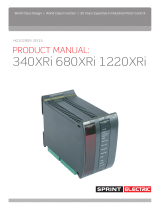
2.1.3 Common Mode Range
The maximum input voltage of T41 or T43 is +/-1000V with respect to 0 Volts. (Common).
Hence an AVF signal of 1000 volts may at the limit have one side at the same voltage with respect to 0
Volts (Common) and still measure linearly.
An AVF signal of 500 volts may have one terminal at + 500 V with respect to 0 Volts (Common) and the
other terminal at +1000V and still measure linearly.
The optimum common mode is for the signal to swing symmetrically with respect to 0 Volts (Com).
These are absolute limits. You should always make allowances for overshoots, ripple etc.
You should always try to ensure the common mode range is as per the optimum if possible. If the neutral of
the 3 phase supply used as the source of the high voltage is close to the earth (which is close to 0V
common) then the common mode range will be optimum.
The common mode range may be reduced if the DC supply to the PLA falls below 20 volts.
+1000 V
-1000 V
0 V (Com)
Positive limit of common mode
range of typical signal
Negative limit of common mode
range of typical signal
See below. Optimum common mode
range of typical signal

Terminals 13
2.1.4 High voltage AC (T45, T47)
The HIGH VOLTAGE AC1, AC2
input is processed by the ‘EL1/2/3 RMS function’. The maximum possible
input voltage is 700V AC. If a DC voltage is entered, it will be rectified and displayed after scaling by 0.7.
Prescale higher voltages prior to connection. The monitor is in DIAGNOSTICS / 169)EL1/2/3 RMS MON.
The optimum common mode is for the signal to swing symmetrically with respect to 0 Volts (Com).
These are absolute limits of the AC peak voltage. You should make allowances for overshoots, ripple etc.
You should always try to ensure the common mode range (CMR) is as per the optimum if possible. If the
neutral of the 3 phase supply used as the source of the high voltage is close to the earth (which is close to
0V ) then the CMR is optimum. The CMR may be reduced if the DC supply to the PLA falls below 20 volts.
2.1.5 Analogue input ACT. (ACT T50, 0Volts T49)
This analogue input is processed via a +/-1 selectable invert/non-invert buffer, followed by an amplifier with
gain 2.5 filter with a time constant of 75mS. The result is output on T29. The parameter for selecting the
invert function is in CONFIGURATION / ANALOG OUTPUTS / 250)Iarm OP RECTIFY. A permanently inverted
version of the input signal may also be monitored using an oscilloscope on a test pin ‘Iarm’. The input
impedance is 100K. See ‘signal test pins’ in section 3 of the main manual.
2.1.6 Control terminals on lower board numbers 53 - 64
0 Volts 53
Reserved for future use 54
Reserved for future use 55
Reserved for future use 56
Reserved for future use 57
Reserved for future use 58
Reserved for future use 59
Reserved for future use 60
Reserved for future use 61
Reserved for future use 62
External DC supply 0 volt connection 63
External DC supply 24 volt connection 20 Volts minimum, 30V maximum. 25 Watt. 64
Note. The supply current requirement for start up with all outputs unloaded is a minimum 0.5 Amp for 0.5s.
The current consumption with outputs unloaded is typically 330mA. Increase accordingly if outputs loaded.
The internal supply is switch-mode and requires proportionately more current if the input voltage reduces.
The message INTERNAL ERROR CODE / SUPPLY PHASE LOSS will appear if the supply dips below 16 Volts,
or fails to exceed 19 Volts on power up. See section 3.6 Supply Loss shutdown in main manual.
Note. The user digital outputs are allocated a budget of 400mA. If this budget is not fully utilised then the
input DC current supply requirement to the PLA is reduced accordingly.
+1000 V
-1000 V
0 V (Com)
Positive limit of common mode
range of typical signal
Negative limit of common mode
range of typical signal
See below. Optimum common mode
range of typical signal


APPLICATION BLOCKS 15
3 APPLICATION BLOCKS
1 Table of contents and Introduction......................................................................3
1.1 Introduction......................................................................................................................... 6
1.2 General Warnings ................................................................................................................. 7
1.3 Warnings and Instructions ..................................................................................................... 8
1.4 General Risks....................................................................................................................... 9
1.5 PLA dimensions.................................................................................................................. 10
2 Terminals ......................................................................................................11
2.1 Control terminals 1 to 36..................................................................................................... 11
3 APPLICATION BLOCKS ...................................................................................15
3.1 General rules...................................................................................................................... 15
3.2 APPLICATION BLOCKS / SUMMER 1, 2 ................................................................................ 18
3.3 APPLICATION BLOCKS / PID 1, 2......................................................................................... 23
3.4 APPLICATION BLOCKS / PARAMETER PROFILER.................................................................... 31
3.5 APPLICATION BLOCKS / REEL DIAMETER CALC .................................................................... 35
3.6 APPLICATION BLOCKS / TAPER TENSION CALC .................................................................... 39
3.7 APPLICATION BLOCKS / TORQUE COMPENSATOR ................................................................ 42
3.8 Centre winding block arrangement ........................................................................................ 51
3.9 APPLICATION BLOCKS / PRESET SPEED ............................................................................... 52
3.10 APPLICATION BLOCKS / MULTI-FUNCTION 1 to 8 ................................................................. 55
3.11 APPLICATION BLOCKS / LATCH .......................................................................................... 58
3.12 APPLICATION BLOCKS / FILTER 1, 2 .................................................................................... 60
3.13 APPLICATION BLOCKS / BATCH COUNTER ........................................................................... 62
3.14 APPLICATION BLOCKS / INTERVAL TIMER............................................................................ 64
3.15 APPLICATION BLOCKS / COMPARATOR 1 to 4...................................................................... 66
3.16 APPLICATION BLOCKS / C/O SWITCH 1 to 4......................................................................... 67
4 PIN table .......................................................................................................69
5 Index ............................................................................................................79
6 Record of PLA manual modifications .................................................................79
7 Record of PLA blocks bug fixes ........................................................................79
8 Changes to product since manual publication .....................................................79
3.1 General rules
3.1.1 Sample times
When application blocks are being processed the
workload on the internal microprocessor is increased.
With no application blocks activated the time taken to
perform all the necessary tasks (cycle time) is
approximately 5mS.
With all the application blocks activated the cycle time
is approximately 10mS. In the future, the designers
expect to add even more application blocks.
It is not expected however that the typical cycle time will ever exceed 30mS. (Bear in mind that it
would be highly unusual for all the application blocks to be activated).
With this in mind it is recommended that the system designer takes care that external logic signals
are stable long enough to be recognised. In order to achieve this, the logic input minimum dwell time has
been specified at 50mS.
It will of course be possible to operate with much lower dwell times than this for simpler installations
where the cycle time is low. There is then the risk that a future re-configuration of the blocks by the user
would increase the cycle time sufficiently to cause sampling problems.
The input low
time must be at
least 50mS
The input high
time must be at
least 50mS

16 APPLICATION BLOCKS
3.1.2 Order of processing
It may be useful for system designers to know the order in which the blocks are processed within each cycle.
0) Analogue inputs 12) Torque compensator
1) Motorised pot 13) Zero interlocks
2) Digital inputs 14) Speed control
3) Reference exchange 15) Preset speed
4) Jumpers 16) Parameter profile
5) Multi-function 17) Latch
6) Alarms 18) Batch counter
7) PID1, 2 19) Interval timer
8) Summer 1, 2 20) Filters
9) Run mode ramps 21) Comparators
10) Diameter calc 22) C/O Switches
11) Taper tension 23) All terminal outputs
3.1.3 Logic levels
Logic inputs will recognise the value zero, (any units), as a logic low. All other numbers, including negative
numbers, will be recognised as a logic high.
3.1.4 Activating blocks
In order to activate a block it is necessary to configure its GOTO window to a PIN other than 400)Block
disconnect. In the CONFIGURATION menu first enter the ENABLE GOTO, GETFROM window and set it to
ENABLED. Then staying in the CONFIGURATION menu proceed to BLOCK OP CONFIG to find the appropriate
GOTO. (Note, The GOTO windows for Multi function 1- 8, Comparator 1-4 and C/O switch 1-4 are contained
within each block menu for convenience). After completing the connection return to the ENABLE GOTO,
GETFROM window and set it to DISABLED.
3.1.5 CONFLICT HELP MENU
If there has been an accidental connection of more than one GOTO to any PIN, then when the ENABLE
GOTO, GETFROM is set to DISABLED, (this is done at the end of a configuration session), the automatic
conflict checker will give the alarm message GOTO CONFLICT. This menu is provided to assist the user in
locating the PIN with the GOTO conflict.
Proceed to the CONFLICT HELP MENU in the CONFIGURATION menu (see product manual) to find the
number of conflicting GOTO connections, and the target PIN that causes the conflict. One of the GOTO
connections must be removed to avoid the conflict.
This process is repeated until there are no conflicts.
Note that this tool is extremely helpful. Without it there is the possibility that user GOTO configuration errors
would cause multiple values to alternately appear at the conflict PIN resulting in unusual system behaviour.
CONFIGURATION 2
CONFLICT HELP MENU 3
CONFLICT HELP MENU 3
NUMBER OF CONFLICTS
CONFLICT HELP MENU 3
MULTIPLE GOTO ON PIN

APPLICATION BLOCKS 17
APPLICATION BLOCKS menu
The application blocks can be used to create
complex control applications.
ENTRY MENU LEVEL 1
APPLICATION BLOCKS 2
APPLICATION BLOCKS 2
FILTER 2 3
APPLICATION BLOCKS 2
BATCH COUNTER 3
APPLICATION BLOCKS 2
INTERVAL TIMER 3
APPLICATION BLOCKS 2
COMPARATORS 1 to 4 3
APPLICATION BLOCKS 2
C/O SWITCH 1 to 4 3
APPLICATION BLOCKS 2
RESERVED FOR FUTURE
APPLICATION BLOCKS 2
RESERVED FOR FUTURE
APPLICATION BLOCKS 2
RESERVED FOR FUTURE
APPLICATION BLOCKS 2
RESERVED FOR FUTURE
APPLICATION BLOCKS 2
RESERVED FOR FUTURE
APPLICATION BLOCKS 2
RESERVED FOR FUTURE
APPLICATION BLOCKS 2
TORQUE COMPENSATOR 3
APPLICATION BLOCKS 2
PRESET SPEED 3
APPLICATION BLOCKS 2
MULTI FUNCTION 1 to 8 3
APPLICATION BLOCKS 2
LATCH 3
APPLICATION BLOCKS 2
FILTER 1 3
APPLICATION BLOCKS 2
TAPER TENSION CALC 3
APPLICATION BLOCKS 2
RESERVED FOR FUTURE
APPLICATION BLOCKS 2
SUMMER 1 3
APPLICATION BLOCKS 2
SUMMER 2 3
APPLICATION BLOCKS 2
PID 1 3
APPLICATION BLOCKS 2
PID 2 3
APPLICATION BLOCKS 2
PARAMETER PROFILE 3
APPLICATION BLOCKS 2
REEL DIAMETER CALC 3

18 APPLICATION BLOCKS
3.2 APPLICATION BLOCKS / SUMMER 1, 2
PIN number range 401 to 427.
Summer 1 and 2 are identical apart from the PIN
numbers. The PIN numbers for both summers are
in the section headings.
There are 2 hidden PINs in each block for CH2 and
CH1 subtotal outputs.
SUMMER1: Pins 691 Ch2 and 692 Ch1.
SUMMER2: Pins 693 Ch2 and 694.Ch1
This menu allows programming of a general
purpose signal summing and scaling block.
APPLICATION BLOCKS 2
SUMMER 1 3
SUMMER 1 3
413)SUMMER1 CLAMP
SUMMER 1 3
401)SUMMER1 OP MON
SUMMER 1 3
402)SUMMER1 SIGN1
SUMMER 1 3
403)SUMMER1 SIGN2
SUMMER 1 3
404)SUMMER1 RATIO1
SUMMER 1 3
405)SUMMER1 RATIO2
SUMMER 1 3
406)SUMMER1 DIVIDER1
SUMMER 1 3
407)SUMMER1 DIVIDER2
SUMMER 1 3
408)SUMMER1 INPUT1
SUMMER 1 3
409)SUMMER1 INPUT2
SUMMER 1 3
410)SUMMER1 INPUT3
SUMMER 1 3
412)SUMMER1 OP INVRT
SUMMER 1 3
411)SUMMER1 DEADBAND

APPLICATION BLOCKS 19
3.2.1 SUMMER 1, 2 / Block diagram
There are 2 identical independant SUMMER blocks
3.2.2 SUMMER 1, 2 / Total output monitor PIN 401 / 415
3.2.3 SUMMER 1, 2 / Sign 1 PIN 402 / 416
PIN 405
PIN 413
PIN 413
PIN 403
PIN 413
PIN 413
PIN 408
Input 1
PIN 412
PIN 401
Output
Pin
692
No display
Subtotal
output
No display
Subtotal
output
Pin
691
PIN 410
Input 3
PIN 409
Input 2
Summer 1
PIN 413
PIN 413
PIN 407
Summer 1
GO TO
PIN 412
PIN
404
PIN
402
PIN
406
PIN
411
dead
band
PIN 419
PIN 427
PIN 427
PIN 417
PIN 427
PIN 427
PIN 422
Input 1
PIN 426
PIN 415
Output
Pin
694
No display
Subtotal
output
No display
Subtotal
output
Pin
693
PIN 424
Input 3
PIN 423
Input 2
Summer 2
PIN 427
PIN 427
PIN 421
Summer 2
GO TO
PIN 426
PIN
418
PIN
416
PIN
420
PIN
425
dead
band
SUMMER 1 3
402)SUMMER1 SIGN1
402)SUMMER1 SIGN1
NON-INVERT
PARAMETER RANGE DEFAULT PIN
SUMMER1 SIGN1 INVERT or NON-INVERT NON-INVERT 402
Used to invert the signal
arriving at input 1.
SUMMER 1 3
401)SUMMER1 OP MON
401)SUMMER1 OP MON
0.00%
PARAMETER RANGE DEFAULT PIN
SUMMER1 OP MON +/-200.00% 0.00% 401
Monitors the final total output
value of the summer block.

20 APPLICATION BLOCKS
3.2.4 SUMMER 1, 2 / Sign 2 PIN 403 / 417
3.2.5 SUMMER 1, 2 / Ratio 1 PIN 404 / 418
3.2.6 SUMMER 1, 2 / Ratio 2 PIN 405 / 419
3.2.7 SUMMER 1, 2 / Divider 1 PIN 406 / 420
3.2.8 SUMMER 1, 2 / Divider 2 PIN 407 / 421
SUMMER 1 3
403)SUMMER1 SIGN2
403)SUMMER1 SIGN2
NON-INVERT
PARAMETER RANGE DEFAULT PIN
SUMMER1 SIGN 2 INVERT or NON-INVERT NON-INVERT 403
Used to invert the signal
arriving at input 2.
SUMMER 1 3
404)SUMMER1 RATIO1
404)SUMMER1 RATIO1
1.0000
PARAMETER RANGE DEFAULT PIN
SUMMER1 RATIO1 +/-3.0000 1.0000 404
Sets the ratio value for the
signal arriving at input 1.
SUMMER 1 3
405)SUMMER1 RATIO2
405)SUMMER1 RATIO2
1.0000
PARAMETER RANGE DEFAULT PIN
SUMMER1 RATIO2 +/-3.0000 1.0000 405
Sets the ratio value for the
signal arriving at input 2.
SUMMER 1 3
406)SUMMER1 DIVIDER1
406)SUMMER1 DIVIDER1
1.0000
PARAMETER RANGE DEFAULT PIN
SUMMER1 DIVIDER1 +/-3.0000 1.0000 406
Sets divisor for signal arriving
at IP1. A zero gives zero output
SUMMER 1 3
407)SUMMER1 DIVIDER2
407)SUMMER1 DIVIDER2
1.0000
PARAMETER RANGE DEFAULT PIN
SUMMER1 DIVIDER2 +/-3.0000 1.0000 407
Sets divisor for signal arriving
at IP2. A zero gives zero output

APPLICATION BLOCKS 21
3.2.9 SUMMER 1, 2 / Input 1 PIN 408 / 422
3.2.10 SUMMER 1, 2 / Input 2 PIN 409 / 423
3.2.11 SUMMER 1, 2 / Input 3 PIN 410 / 424
3.2.12 SUMMER 1, 2 / Deadband PIN 411 / 425
3.2.13 SUMMER 1, 2 / Output sign inverter PIN 412 / 426
SUMMER 1 3
408)SUMMER1 INPUT1
408)SUMMER1 INPUT1
0.00%
PARAMETER RANGE DEFAULT PIN
SUMMER1 INPUT1 +/-300.00% 0.00% 408
Sets value for input 1.
SUMMER 1 3
409)SUMMER1 INPUT2
409)SUMMER1 INPUT2
0.00%
PARAMETER RANGE DEFAULT PIN
SUMMER1 INPUT2 +/-300.00% 0.00% 409
Sets value for input 2.
SUMMER 1 3
410)SUMMER1 INPUT3
410)SUMMER1 INPUT3
0.00%
PARAMETER RANGE DEFAULT PIN
SUMMER1 INPUT3 +/-300.00% 0.00% 410
Sets value for input 3.
SUMMER 1 3
411)SUMMER1 DEADBAND
411)SUMMER1 DEADBAND
0.00%
PARAMETER RANGE DEFAULT PIN
SUMMER1 DEADBAND 0.00 to 100.00% 0.00% 411
Sets +/- % deadband width
centred on 0.00% for input 1.
SUMMER 1 3
412)SUMMER1 OP INVRT
412)SUMMER1 OP INVRT
NON-INVERT
PARAMETER RANGE DEFAULT PIN
SUMMER1 OP INVRT INVERT / NON-INVERT NON-INVERT 412
Used to invert the output signal
from the summing block.
/