Page is loading ...

INSTALLATION INSTRUCTIONS
FLUORESCENT WALL PACK
Document: CI308X52R0
Date: 2/1/2013
Created by: TMT
DCR#: 2012-071
E-WPC2
Error!
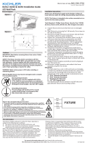
1. This carton contains fixture, lamp, and wall mounting box.
2. Review template on backside of installation sheet.
NOTE: Template includes minimum mounting distance to
ceilings.
3. Place mounting box over junction box or conduit. If mounting
over junction box, a 2-1/2" inspection hole knockout is
included. See Figure 1.
4. For surface wiring (3) 1/2" threaded holes are available. See
Figure 1.
5. IMPORTANT – Keyholes located inside box are for
alignment only. Fixture is to be supported by (3) 3/16"
mounting holes. Recess surrounding mounting hole will
accommodate a 1/4" bolt head. Select appropriate mounting
hardware for mounting surface.
6. Place a minimum of a 1/4" bead of silicone rubber on black
gasket on back of mounting box. See Figure 1a.
FIGURE 1a
7. Before securing fixture to wall mounting surface, make sure
mounting box is level.
8. Secure mounting box to wall.
1. Loosen (2) phillips lens screws located on the bottom of lens.
Lift lens up and remove from fixture.
2. Loosen (2) torx screws (use 1/4" nut driver or T-20 torx) and
remove junction box cover.
3. If mounting fixture over surface mounted conduit, knockout
conduit opening on either the top or sides as required. See
Figure 2. Knockouts can be removed by using a hammer or
pliers.
4. Place fixture on mounting box making sure that screws on
mounting box insert through keyhole opening on fixture.
5. Tighten torx screws use a T-20 torx or 1/4" nut driver.
6. See electrical connection instructions.
7. Insert supplied lamp into socket.
8. Replace glass lens by hooking hinge on top of casting and
allowing lens to close. Tighten (2) phillips screw
INSTALLATION OF MOUNTING BOX
INSTALLATION OF FIXTURE
IMPORTANT SAFEGUARDS
1. RISK OF FIRE AND ELECTRICAL SHOCK. THIS
PRODUCT IS TO BE INSTALLED BY A QUALIFIED
ELECTRICIAN ONLY.
2. To avoid the possibility of electrical shock, turn off power
supply before installation or service.
FIGURE 2
FIGURE 1

INSTALLATION INSTRUCTIONS
FLUORESCENT WALL PACK
Document: CI308X52R0
Date: 2/1/2013
Created by: TMT
DCR#: 2012-071
WARNING – To avoid the possibility of electrical shock; turn
off power supply before making any electrical connections.
CONNECTING INCOMING POWER:
1. Connect the green with yellow striped leads from mounting box
and fixture to the incoming ground.
2. Connect the incoming voltage lead (hot) to the black lead and
the neutral to the white lead.
NOTE: When using (2) legs (hot), connect one leg (hot) to the
black lead and the other leg (hot) to the white lead.
3. Replace wiring compartment box cover and tighten screws
using T-20 torx or 1/4" nut driver.
ELECTRICAL CONNECTIONS
/

