Page is loading ...

NOTE: This lighting fixture is designed for outdoor lighting services, and should not be used in areas of limited ventilation or in high ambient temperature
enclosures. It must be stored in a dry location prior to installation. Do not expose lighting fixture to rain, dust or other environmental conditions prior
to installation. Construction is suitable for down lighting only. Do not place the fixture onto the ground with the LED/optical side facing down during
the installation process. Best results will be obtained if installed and maintained according to the following recommendations.
INSTALLATION
Your lighting fixture has been shipped with one of several types of mounting options. Please follow the installation instructions specific to the catalog
part that you ordered. If the maintenance plan for your specific mounting application calls for hosing down the fixture, all supply wires used must include
wet rated wire insulation and splice components.
TOOLS REQUIRED:
Flat blade screw driver, Phillips head screw driver, electrical wiring tools.
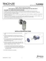
CEILING MOUNT / QUICK MOUNT [FIG 1]:
1. Remove top knockout in Top Quick Mount Bracket.
2. Pull the supply wires through j-box and through the top knockout of the top
quick mount bracket—decorative cage.
3. Assemble top quick mount bracket—decorative cage to j-box [not supplied]
located in ceiling using appropriate hardware [not supplied] for the junction interface
[j-box must be secured to ceiling structure and must be able to support a minimum
of 20 lbs.].
4. Lift fixture assembly to the top quick mount bracket that has been attached to the
ceiling/ j-box and connect the safety cable to the loop provided in the top quick mount box.
5. Connect supply wires to appropriate fixture leads with wire nuts:
a. Supply side line voltage wire to black fixture lead.
b. Supply side neutral wire to white fixture lead.
c. Supply side ground wire to green fixture lead.
6. Push the wire splices back into j-box slide the bottom quick mount bracket
into the top quick mount bracket and secure with two [2] screws.
7. The fixture is now ready to be energized.
Valet LED
Sheet 1 of 4
3/26/10 IMI-727
INSTALLATION INSTRUCTIONS
IMPORTANT : READ BEFORE REMOVING FIXTURE FROM CARTON. RETAIN FOR FUTURE REFERENCE.
GENERAL: Upon receipt of fixture thoroughly inspect for any freight
damage, which should be brought to the attention of the delivery
carrier. Compare the catalog description listed on the packing slip with
the fixture label on the housing to be sure the correct merchandise has
been received.
SAFETY: This fixture must be wired in accordance with the National
Electrical Code, National Electrical Safety Code and applicable local
codes and ordinances. Proper grounding is required to insure personal
safety. Carefully observe grounding procedure under installation
section. This fixture is not suitable for Hazardous or Classified
Locations. This product must be installed in accordance with the
applicable installation code by a person familiar with the construction
and operation of the product and hazards involved. Consult a qualified
electrician to ensure correct branch circuit conductor.
WARNING: Risk of Fire/Electric Shock. If not qualified, consult an
electrician.
WARNING: Risk of Electric Shock. Disconnect power at fuse or circuit
breaker before installing or servicing.
WARNING: Risk of burn. Disconnect power and allow fixture to cool
before servicing.
WARNING: Risk of personal injury—Fixture may become damaged
and/or unstable if not installed properly. Tighten all fixture components
to their recommended torque values.
Customer First Center 1121 Highway 74 South Peachtree City, GA 30269 770.486.4800 FAX 770.486.4801 ADH100011
These instructions do not claim to cover all details or variations in the equipment, procedure, or process described, nor to provide directions for meeting every possible contingency during installation,
operation or maintenance. When additional information is desired to satisfy a problem not covered sufficiently for user’s purpose, please contact your nearest representative.
NOTE: Specifications and dimensions subject to change without notice.
TOP QUICK
MOUNT BRACKET
DECORATIVE CAGE
SAFETY
CABLE
HOOK
SAFETY CABLE LOOP
BOTTOM QUICK
MOUNT BRACKET
TO JUNCTION BOX (NOT SUPPLIED)
FIG. 1
NOTE: For wet location usage, use appropriate outdoor caulking compound
[latex, silicone, etc.] to seal the joint between the die-cast housing
and the mounting surface to avoid water entry through the wire
opening in the housing. This particular mounting configuration is
rated for ambient usage of 25°C.
BI-LEVEL SWITCHING [IF EQUIPPED]
For Bi-level switching, the input leads to the fixture will be independently labeled
to indicate dimming preferences as appropriate [as defined by the order requirements].
Two [2] Separate supply lines of line voltage, neutral and ground must be provided to the
fixture to enable the bi-level switching functionality of the fixture.
MAINTENANCE
A regular maintenance schedule should be followed to retain optimal light output and
thermal performance. Optical lens cleaning should be performed with a clean dry cloth
to remove any dust or other contaminants. Additional cleaning can be performed with
non-abrasive acrylic cleansing solution.
INSTALLATION INSTRUCTIONS
IMPORTANT : READ BEFORE REMOVING FIXTURE FROM CARTON. RETAIN FOR FUTURE REFERENCE.
Customer First Center 1121 Highway 74 South Peachtree City, GA 30269 770.486.4800 FAX 770.486.4801 ADH100011
These instructions do not claim to cover all details or variations in the equipment, procedure, or process described, nor to provide directions for meeting every possible contingency during installation,
operation or maintenance. When additional information is desired to satisfy a problem not covered sufficiently for user’s purpose, please contact your nearest representative.
NOTE: Specifications and dimensions subject to change without notice.
Valet LED
Sheet 4 of 4
3/26/10 IMI-727
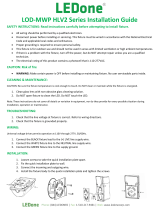
DRILL POINT #1 DRILL POINT #2
DRILL POINT #3
3-3/4"
5-5/16"
4"
SUPPLY WIRE
ENTRY POINT
FIG. 5

TOOLS REQUIRED:
Phillips head screw driver, electrical wiring tools.
WALL MOUNT [FIG 2]:
1. Pull the supply wires out of j-box [not included] and through the large hole in
the center of the attachment plate.
2. Secure attachment plate to j-box / wall using two [2] screws [not supplied].
3. Connect supply wires to appropriate fixture leads with wire nuts:
a. Supply side line voltage wire to black fixture lead.
b. Supply side neutral wire to white fixture lead.
c. Supply side ground wire to green fixture lead.
4. Push the wire splices back into j-box and mount the fixture assembly to the
attachment plate by tightening the two [2] set screws at the top
and bottom of the decorative wall mount plate.
5. The fixture is now ready to be energized.
NOTE: For wet location usage, use appropriate outdoor caulking compound
[latex, silicone, etc.] to seal the joint between decorative wall mount
plate and the mounting surface.
TOOLS REQUIRED:
Ratchet and 3/8" socket, adjustable wrench, Phillips head screw driver, electrical wiring tools.
TRUNNION MOUNT [FIG 3]:
1. Feed fixture wires into cast splice box supplied with the fixture and thread the splice box
into the top center opening of the fixture.
2. Install bottom trunnion mount bracket to studs located on top of the light fixture as shown
FIG. 3 using two [2] #10 locking nuts. Repeat for other bottom trunnion mount bracket.
3. Locate and install top trunnion mount bracket to bottom brackets using supplied four [4]
3/8" hex bolts, eight [8] lock washers and four [4] nuts, but do not tighten completely.
4. Slide top trunnion mount bracket to the required installation height for your
particular application. Tighten trunnion bolts/nuts to lock the proper height.
5. Fixture assembly may now be secured to the ceiling using proper hardware
[not supplied]. Hardware must be capable to support 20 lbs.
6. Pull the supply wires into the cast j-box through the side opening and
connect wire to appropriate fixture leads with wire nuts:
a. Supply side line voltage wire to black fixture lead.
b. Supply side neutral wire to white fixture lead.
c. Supply side ground wire to green fixture lead.
7. Push all wire back into splice box, making sure that all splices are located
within the splice box enclosure.
8. Install gasket and cover onto j-box enclosure with two [2] screws
9. The fixture is now ready to be energized.
INSTALLATION INSTRUCTIONS
IMPORTANT : READ BEFORE REMOVING FIXTURE FROM CARTON. RETAIN FOR FUTURE REFERENCE.
Customer First Center 1121 Highway 74 South Peachtree City, GA 30269 770.486.4800 FAX 770.486.4801 ADH100011
These instructions do not claim to cover all details or variations in the equipment, procedure, or process described, nor to provide directions for meeting every possible contingency during installation,
operation or maintenance. When additional information is desired to satisfy a problem not covered sufficiently for user’s purpose, please contact your nearest representative.
NOTE: Specifications and dimensions subject to change without notice.
Valet LED
Sheet 2 of 4
3/26/10 IMI-727
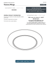
ATTACHMENT
PLATE
SET SCREW
SET
SCREW
DECORATIVE
WALL PLATE
TO JUNCTION BOX
(NOT SUPPLIED)
FIG. 2
BOTTOM TRUNNION
MOUNT BRACKET
BOTTOM TRUNNION
MOUNT BRACKET
SPLICE
COMPARTMENT
JUNCTION
BOX
COVER
GASKET
TOP TRUNNION MOUNT BRACKET
3/8" BOLT
LOCK WASHER
LOCK WASHER
NUT
FIG. 3
TOOLS REQUIRED:
Level, adjustable wrench, Phillips head screw driver, electrical wiring tools.
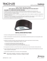
ADJUSTABLE PENDANT MOUNT WITH BIRDGUARD [FIG. 4]:
1. Feed supply wire through the 3/4" threaded end pendant [not supplied].
2. Thread the 1st conduit nut onto the end of the threaded 3/4" conduit.
Place the conduit through the circular opening at the top of the adjustable
pendant bracket. The 1st conduit nut should rest on top of the adjustable
pendant bracket. Secure the pendant to the adjustable pendant bracket
by threading the 2nd conduit nut underneath the adjustable bracket.
Tighten both conduit nuts securely. [Note – follow all applicable electrical
codes for wireway exits – this may require a separate hub [not supplied]
to be used at the base of the conduit].
3. Thread the four [4] lock nuts supplied to the studs located on top of the
housing. These should be threaded about halfway down each of the studs.
4. Lift the fixture to the adjustable pendant bracket and place the four [4]
nuts/studs through the keyhole slots in the adjustable bracket. Slide the
fixture along the guide slots past each of the keyhole openings.
5. Adjust the location of the bracket such that the fixture hangs level.
6. Fully tighten [33 in-lbs] the four [4] lock nuts to lock the fixture into place.
Do not overtighten as this could damage the studs in the housing.
7. Connect the supply lead wires to the appropriate fixture leads using
UL approved splicing/wire nuts:
a. Supply side ground wire to green fixture lead.
b. Supply side neutral wire to white fixture lead.
c. Supply side line voltage wire to black fixture lead.
8. Place the covers over each end of the adjustable bracket and screw
into place using the supplied #8 self tapping screws.
9. The fixture is now ready to be energized.
TOOLS REQUIRED:
Hardware to secure to ceiling structure [not supplied], Phillips head screwdriver, electrical wiring tools, drill.
SURFACE MOUNT [FIG. 5]:
1. Loosen four [4] screws on front of light fixture. Remove Cover and set aside.
2. Remove LightBAR assembly from fixture by inserting a screwdriver and carefully lifting the Lightbar assembly.
This assembly is secured to the fixture by a safety lanyard to prevent damage/injury. Do not remove this lanyard.
3. Drill through the top side of the casting. See FIG. 5 for the suggested drill pattern to avoid damage to any internal
components to the fixture. Only drill from the inside of the fixture.
4. Feed supply wires through the 3/4" NPT opening on top of the fixture.
5. Connect supply wires to appropriate fixture leads with wire nuts inside the housing:
a. Supply side ground wire to green fixture lead
b. Supply side neutral wire to white fixture lead
c. Supply side line voltage wire to black fixture lead
6. Secure housing to mounting surface using hardware [not supplied].
7. Replace LightBAR assembly and cover back onto the housing and tighten the four [4] screws. Make certain no wiring
is trapped between the LightBAR assembly and the side of the housing to avoid damage/pinched wires.
8. The fixture is now ready to energize.
INSTALLATION INSTRUCTIONS
IMPORTANT : READ BEFORE REMOVING FIXTURE FROM CARTON. RETAIN FOR FUTURE REFERENCE.
Customer First Center 1121 Highway 74 South Peachtree City, GA 30269 770.486.4800 FAX 770.486.4801 ADH100011
These instructions do not claim to cover all details or variations in the equipment, procedure, or process described, nor to provide directions for meeting every possible contingency during installation,
operation or maintenance. When additional information is desired to satisfy a problem not covered sufficiently for user’s purpose, please contact your nearest representative.
NOTE: Specifications and dimensions subject to change without notice.
Valet LED
Sheet 3 of 4
3/26/10 IMI-727
COVER #1
COVER #1
3/4" THREADED
END PENDANT
CONDUIT NUT #1
CONDUIT NUT #2
(2) #10 STUDS/NUTS
ADJUSTABLE
PENDANT BRACKET
FIG. 4

TOOLS REQUIRED:
Phillips head screw driver, electrical wiring tools.
WALL MOUNT [FIG 2]:
1. Pull the supply wires out of j-box [not included] and through the large hole in
the center of the attachment plate.
2. Secure attachment plate to j-box / wall using two [2] screws [not supplied].
3. Connect supply wires to appropriate fixture leads with wire nuts:
a. Supply side line voltage wire to black fixture lead.
b. Supply side neutral wire to white fixture lead.
c. Supply side ground wire to green fixture lead.
4. Push the wire splices back into j-box and mount the fixture assembly to the
attachment plate by tightening the two [2] set screws at the top
and bottom of the decorative wall mount plate.
5. The fixture is now ready to be energized.
NOTE: For wet location usage, use appropriate outdoor caulking compound
[latex, silicone, etc.] to seal the joint between decorative wall mount
plate and the mounting surface.
TOOLS REQUIRED:
Ratchet and 3/8" socket, adjustable wrench, Phillips head screw driver, electrical wiring tools.
TRUNNION MOUNT [FIG 3]:
1. Feed fixture wires into cast splice box supplied with the fixture and thread the splice box
into the top center opening of the fixture.
2. Install bottom trunnion mount bracket to studs located on top of the light fixture as shown
FIG. 3 using two [2] #10 locking nuts. Repeat for other bottom trunnion mount bracket.
3. Locate and install top trunnion mount bracket to bottom brackets using supplied four [4]
3/8" hex bolts, eight [8] lock washers and four [4] nuts, but do not tighten completely.
4. Slide top trunnion mount bracket to the required installation height for your
particular application. Tighten trunnion bolts/nuts to lock the proper height.
5. Fixture assembly may now be secured to the ceiling using proper hardware
[not supplied]. Hardware must be capable to support 20 lbs.
6. Pull the supply wires into the cast j-box through the side opening and
connect wire to appropriate fixture leads with wire nuts:
a. Supply side line voltage wire to black fixture lead.
b. Supply side neutral wire to white fixture lead.
c. Supply side ground wire to green fixture lead.
7. Push all wire back into splice box, making sure that all splices are located
within the splice box enclosure.
8. Install gasket and cover onto j-box enclosure with two [2] screws
9. The fixture is now ready to be energized.
INSTALLATION INSTRUCTIONS
IMPORTANT : READ BEFORE REMOVING FIXTURE FROM CARTON. RETAIN FOR FUTURE REFERENCE.
Customer First Center 1121 Highway 74 South Peachtree City, GA 30269 770.486.4800 FAX 770.486.4801 ADH100011
These instructions do not claim to cover all details or variations in the equipment, procedure, or process described, nor to provide directions for meeting every possible contingency during installation,
operation or maintenance. When additional information is desired to satisfy a problem not covered sufficiently for user’s purpose, please contact your nearest representative.
NOTE: Specifications and dimensions subject to change without notice.
Valet LED
Sheet 2 of 4
3/26/10 IMI-727
ATTACHMENT
PLATE
SET SCREW
SET
SCREW
DECORATIVE
WALL PLATE
TO JUNCTION BOX
(NOT SUPPLIED)
FIG. 2
BOTTOM TRUNNION
MOUNT BRACKET
BOTTOM TRUNNION
MOUNT BRACKET
SPLICE
COMPARTMENT
JUNCTION
BOX
COVER
GASKET
TOP TRUNNION MOUNT BRACKET
3/8" BOLT
LOCK WASHER
LOCK WASHER
NUT
FIG. 3
TOOLS REQUIRED:
Level, adjustable wrench, Phillips head screw driver, electrical wiring tools.
ADJUSTABLE PENDANT MOUNT WITH BIRDGUARD [FIG. 4]:
1. Feed supply wire through the 3/4" threaded end pendant [not supplied].
2. Thread the 1st conduit nut onto the end of the threaded 3/4" conduit.
Place the conduit through the circular opening at the top of the adjustable
pendant bracket. The 1st conduit nut should rest on top of the adjustable
pendant bracket. Secure the pendant to the adjustable pendant bracket
by threading the 2nd conduit nut underneath the adjustable bracket.
Tighten both conduit nuts securely. [Note – follow all applicable electrical
codes for wireway exits – this may require a separate hub [not supplied]
to be used at the base of the conduit].
3. Thread the four [4] lock nuts supplied to the studs located on top of the
housing. These should be threaded about halfway down each of the studs.
4. Lift the fixture to the adjustable pendant bracket and place the four [4]
nuts/studs through the keyhole slots in the adjustable bracket. Slide the
fixture along the guide slots past each of the keyhole openings.
5. Adjust the location of the bracket such that the fixture hangs level.
6. Fully tighten [33 in-lbs] the four [4] lock nuts to lock the fixture into place.
Do not overtighten as this could damage the studs in the housing.
7. Connect the supply lead wires to the appropriate fixture leads using
UL approved splicing/wire nuts:
a. Supply side ground wire to green fixture lead.
b. Supply side neutral wire to white fixture lead.
c. Supply side line voltage wire to black fixture lead.
8. Place the covers over each end of the adjustable bracket and screw
into place using the supplied #8 self tapping screws.
9. The fixture is now ready to be energized.
TOOLS REQUIRED:
Hardware to secure to ceiling structure [not supplied], Phillips head screwdriver, electrical wiring tools, drill.
SURFACE MOUNT [FIG. 5]:
1. Loosen four [4] screws on front of light fixture. Remove Cover and set aside.
2. Remove LightBAR assembly from fixture by inserting a screwdriver and carefully lifting the Lightbar assembly.
This assembly is secured to the fixture by a safety lanyard to prevent damage/injury. Do not remove this lanyard.
3. Drill through the top side of the casting. See FIG. 5 for the suggested drill pattern to avoid damage to any internal
components to the fixture. Only drill from the inside of the fixture.
4. Feed supply wires through the 3/4" NPT opening on top of the fixture.
5. Connect supply wires to appropriate fixture leads with wire nuts inside the housing:
a. Supply side ground wire to green fixture lead
b. Supply side neutral wire to white fixture lead
c. Supply side line voltage wire to black fixture lead
6. Secure housing to mounting surface using hardware [not supplied].
7. Replace LightBAR assembly and cover back onto the housing and tighten the four [4] screws. Make certain no wiring
is trapped between the LightBAR assembly and the side of the housing to avoid damage/pinched wires.
8. The fixture is now ready to energize.
INSTALLATION INSTRUCTIONS
IMPORTANT : READ BEFORE REMOVING FIXTURE FROM CARTON. RETAIN FOR FUTURE REFERENCE.
Customer First Center 1121 Highway 74 South Peachtree City, GA 30269 770.486.4800 FAX 770.486.4801 ADH100011
These instructions do not claim to cover all details or variations in the equipment, procedure, or process described, nor to provide directions for meeting every possible contingency during installation,
operation or maintenance. When additional information is desired to satisfy a problem not covered sufficiently for user’s purpose, please contact your nearest representative.
NOTE: Specifications and dimensions subject to change without notice.
Valet LED
Sheet 3 of 4
3/26/10 IMI-727
COVER #1
COVER #1
3/4" THREADED
END PENDANT
CONDUIT NUT #1
CONDUIT NUT #2
(2) #10 STUDS/NUTS
ADJUSTABLE
PENDANT BRACKET
FIG. 4

NOTE: This lighting fixture is designed for outdoor lighting services, and should not be used in areas of limited ventilation or in high ambient temperature
enclosures. It must be stored in a dry location prior to installation. Do not expose lighting fixture to rain, dust or other environmental conditions prior
to installation. Construction is suitable for down lighting only. Do not place the fixture onto the ground with the LED/optical side facing down during
the installation process. Best results will be obtained if installed and maintained according to the following recommendations.
INSTALLATION
Your lighting fixture has been shipped with one of several types of mounting options. Please follow the installation instructions specific to the catalog
part that you ordered. If the maintenance plan for your specific mounting application calls for hosing down the fixture, all supply wires used must include
wet rated wire insulation and splice components.
TOOLS REQUIRED:
Flat blade screw driver, Phillips head screw driver, electrical wiring tools.
CEILING MOUNT / QUICK MOUNT [FIG 1]:
1. Remove top knockout in Top Quick Mount Bracket.
2. Pull the supply wires through j-box and through the top knockout of the top
quick mount bracket—decorative cage.
3. Assemble top quick mount bracket—decorative cage to j-box [not supplied]
located in ceiling using appropriate hardware [not supplied] for the junction interface
[j-box must be secured to ceiling structure and must be able to support a minimum
of 20 lbs.].
4. Lift fixture assembly to the top quick mount bracket that has been attached to the
ceiling/ j-box and connect the safety cable to the loop provided in the top quick mount box.
5. Connect supply wires to appropriate fixture leads with wire nuts:
a. Supply side line voltage wire to black fixture lead.
b. Supply side neutral wire to white fixture lead.
c. Supply side ground wire to green fixture lead.
6. Push the wire splices back into j-box slide the bottom quick mount bracket
into the top quick mount bracket and secure with two [2] screws.
7. The fixture is now ready to be energized.
Valet LED
Sheet 1 of 4
3/26/10 IMI-727
INSTALLATION INSTRUCTIONS
IMPORTANT : READ BEFORE REMOVING FIXTURE FROM CARTON. RETAIN FOR FUTURE REFERENCE.
GENERAL: Upon receipt of fixture thoroughly inspect for any freight
damage, which should be brought to the attention of the delivery
carrier. Compare the catalog description listed on the packing slip with
the fixture label on the housing to be sure the correct merchandise has
been received.
SAFETY: This fixture must be wired in accordance with the National
Electrical Code, National Electrical Safety Code and applicable local
codes and ordinances. Proper grounding is required to insure personal
safety. Carefully observe grounding procedure under installation
section. This fixture is not suitable for Hazardous or Classified
Locations. This product must be installed in accordance with the
applicable installation code by a person familiar with the construction
and operation of the product and hazards involved. Consult a qualified
electrician to ensure correct branch circuit conductor.
WARNING: Risk of Fire/Electric Shock. If not qualified, consult an
electrician.
WARNING: Risk of Electric Shock. Disconnect power at fuse or circuit
breaker before installing or servicing.
WARNING: Risk of burn. Disconnect power and allow fixture to cool
before servicing.
WARNING: Risk of personal injury—Fixture may become damaged
and/or unstable if not installed properly. Tighten all fixture components
to their recommended torque values.
Customer First Center 1121 Highway 74 South Peachtree City, GA 30269 770.486.4800 FAX 770.486.4801 ADH100011
These instructions do not claim to cover all details or variations in the equipment, procedure, or process described, nor to provide directions for meeting every possible contingency during installation,
operation or maintenance. When additional information is desired to satisfy a problem not covered sufficiently for user’s purpose, please contact your nearest representative.
NOTE: Specifications and dimensions subject to change without notice.
TOP QUICK
MOUNT BRACKET
DECORATIVE CAGE
SAFETY
CABLE
HOOK
SAFETY CABLE LOOP
BOTTOM QUICK
MOUNT BRACKET
TO JUNCTION BOX (NOT SUPPLIED)
FIG. 1
NOTE: For wet location usage, use appropriate outdoor caulking compound
[latex, silicone, etc.] to seal the joint between the die-cast housing
and the mounting surface to avoid water entry through the wire
opening in the housing. This particular mounting configuration is
rated for ambient usage of 25°C.
BI-LEVEL SWITCHING [IF EQUIPPED]
For Bi-level switching, the input leads to the fixture will be independently labeled
to indicate dimming preferences as appropriate [as defined by the order requirements].
Two [2] Separate supply lines of line voltage, neutral and ground must be provided to the
fixture to enable the bi-level switching functionality of the fixture.
MAINTENANCE
A regular maintenance schedule should be followed to retain optimal light output and
thermal performance. Optical lens cleaning should be performed with a clean dry cloth
to remove any dust or other contaminants. Additional cleaning can be performed with
non-abrasive acrylic cleansing solution.
INSTALLATION INSTRUCTIONS
IMPORTANT : READ BEFORE REMOVING FIXTURE FROM CARTON. RETAIN FOR FUTURE REFERENCE.
Customer First Center 1121 Highway 74 South Peachtree City, GA 30269 770.486.4800 FAX 770.486.4801 ADH100011
These instructions do not claim to cover all details or variations in the equipment, procedure, or process described, nor to provide directions for meeting every possible contingency during installation,
operation or maintenance. When additional information is desired to satisfy a problem not covered sufficiently for user’s purpose, please contact your nearest representative.
NOTE: Specifications and dimensions subject to change without notice.
Valet LED
Sheet 4 of 4
3/26/10 IMI-727
DRILL POINT #1 DRILL POINT #2
DRILL POINT #3
3-3/4"
5-5/16"
4"
SUPPLY WIRE
ENTRY POINT
FIG. 5
/