Page is loading ...

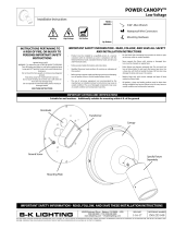
PM2RM TREE STRAP™ Driver Housing
Constant Current Driver
REVISION DATE
12-13-11
REFERENCE NUMBER
INS000795.6
40429 Brickyard Drive • Madera, CA 93636 • USA
559.438.5800 • FAX 559.438.5900
www.bklighting.com • [email protected]
B-K LIGHTING
THIS DOCUMENT CONTAINS PROPRIETARY INFORMATION OF B-K LIGHTING, INC. AND ITS RECEIPT OR POSSESSION DOES NOT CONVEY ANY RIGHTS TO REPRODUCE, DISCLOSE ITS CONTENTS, OR TO MANUFACTURE, USE OR SELL ANYTHING IT MAY
DESCRIBE. REPRODUCTION, DISCLOSURE OR USE WITHOUT SPECIFIC WRITTEN AUTHORIZATION OF B-K LIGHTING, INC. IS STRICTLY FORBIDDEN.
NEEDED
FOR
INSTALLATION:
UPM housing
Adjustable tree strap
Patented 1/2” NPT knockouts*
UPM faceplate
By Others
* UPM is covered in whole or in part by US patent #6,940,012
Warning High Voltage Hot Surface
• Product must be installed by a qualified person in a manner
consistent with its intended use and in compliance with the
National Electrical Code, Canadian Electrical Code, and all Local
and Provincial Codes.
• Follow product label information and instructions.
• Qualified Personnel must perform all servicing or relamping of
this product.
• Before wiring to power supply and during servicing or relamping,
turn off power at fuse or circuit breaker before service.
• The use of accessory equipment not recommended by the
manufacturer or installed contrary to instructions may cause an
unsafe condition. The use of damaged components may cause
an unsafe condition and void product warranty.
IMPORTANT SAFETY INFORMATION - READ, FOLLOW, AND SAVE ALL SAFETY
AND INSTALLATION INSTRUCTIONS
• Do not block light emanating from product in whole or part,
as this may cause an unsafe condition.
• Never operate the fixture with missing or damaged lens.
Lens must be cleaned on regular basis.
• Entire fixture may become extremely hot. Do not touch hot
lens or fixture body. Do not touch the lamp at any time. Use
a clean, dry, soft cloth to handle the lamp. Oil from skin may
damage the lamp and cause it to rupture.
• Replace lamp only with correct wattage and type of lamp
marked on fixture label.
• All gaskets, o-rings and sealing surfaces must be kept clean
during installation and service; failure to do this may cause an
unsafe condition and void product warranty.
INSTRUCTIONS PERTAINING TO
A RISK OF FIRE, OR INJURY TO
PERSONS IMPORTANT SAFETY
INSTRUCTIONS
Lighted lamp is HOT!
WARNING - To reduce the risk of FIRE OR INJURY TO PERSONS:
Turn off/unplug and allow to cool before replacing lamp.
Lamp gets HOT quickly! Contact only switch/plug when
turning on.
Do not touch hot lens, guard, or enclosure (see diagram/
picture).
Keep lamp away from materials that may burn.
Do no touch the lamp at any time. Use a soft cloth. Oil
from skin may damage lamp.
Do not operate the luminaire fitting with a missing or
damaged shield.
SAVE THESE INSTRUCTIONS
· Suitable for wet locations
IMPORTANT LISTINGS AND CERTIFICATIONS
5/64” allen wrench
Wire connectors
Hammer
Phillips screwdriver
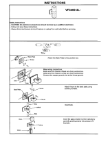
REMOTE WIRING
LED Driver
Remote driver installations require inter-connected
wiring between the LED and driver (by others).
Drivers have specific wiring requirements between
these components. Driver manufacturers regularly
recommend the following wiring details for such
installations:
• Do not exceed 50 foot overall wiring distance
using 12 gauge copper wire.
Failure to comply with specific wiring
requirements will void product warranty.

REVISION DATE
12-13-11
REFERENCE NUMBER
INS000795.6
40429 Brickyard Drive • Madera, CA 93636 • USA
559.438.5800 • FAX 559.438.5900
www.bklighting.com • [email protected]
B-K LIGHTING
5. Pull branch circuit wiring necessary for
installation (By Others.)
6. Attach tether wire under screw head at the base
of the UPM housing and tighten. Slowly lower
the faceplate until tether is taut.
NOTE: Faceplate tether supplied with UPM
is designed as an installation aid and NOT a
safety cable. Do not add weight to, or drop
faceplate.
GroundHotNeutral
7. Use wire connectors (By Others) to connect driver
primary leads to branch circuit wires. Connect
incoming ground and driver ground to ground
wire provided in UPM housing. See wiring
diagram.
9. Make sure UPM housing gasket is free of
any dirt or debris. Attach the faceplate by
tightening the (4) #6-32 captive screws evenly
to 6-9 in/lbs using a 5/64” allen wrench.
4. Connect 1/2” conduit connector through female
threaded conduit entry.
NOTE: Surface conduit is a common entrance
for water if not properly sealed. Seal connector
threads and conduit pipe with a suitable sealant
(Teflon tape, adhesive, etc). Sealing the conduit
after knockouts are removed is required to
maintain warranty
Wiring Diagram.
8. Pull lamp leads into UPM housing and connect
to driver secondary leads using approved wire
connectors (By Others).
NOTE: See driver warning on page 1. Failure
to comply with wiring requirements will
void warranty.
IMPORTANT SAFETY INFORMATION LISTED ON REVERSE
READ, FOLLOW, AND SAVE ALL SAFETY AND INSTALLATION INSTRUCTIONS
ETL LISTED
CONFORMS TO ANSI/UL
STANDARD 1598
CERTIFIED TO CAN/CSA
STANDARD C22.2 NO. 250
1. Remove Patented Knockout(s) as necessary from
the inside of the UPM housing for branch circuit
wiring and lamp leads to remote mounted
fixture. Leave remaining unused knockouts in
place to maintain seal.
NOTE: Patented design featuring a silicone ‘O’
Ring allowing knockout to be tapped back into
place to renew seal integrity.
2. Use adjustable strap provided to attach UPM
housing to tree. Tighten by pulling on the
adjustable strap until secure.
3. Optional Step on PM1 & PM2: Thread safety
cable through hole on the back of the UPM
housing. Feed safety cable through opposing
ends of the connector. Pull on wires to assure
the connection is secure. Leave enough slack in
safety cable for tree growth. Adjustments can
be made by pressing release spring with a pin or
3/64” allen tool.
PM2RM TREE STRAP™ Driver Housing
Constant Current Driver
LAMP
BLUE
WHITE
QUICK DISCONNECT
LINE (BLACK)
NEUTRAL (WHITE)
GROUND (GREEN)
BARE WIRE
IN UPM
RED
BLACK
BLUE
WHITE
GREEN
DRIVER

REVISION DATE
12-13-11
REFERENCE NUMBER
INS000795.7
40429 Brickyard Drive • Madera, CA 93636 • USA
559.438.5800 • FAX 559.438.5900
www.bklighting.com • [email protected]
B-K LIGHTING
THIS DOCUMENT CONTAINS PROPRIETARY INFORMATION OF B-K LIGHTING, INC. AND ITS RECEIPT OR POSSESSION DOES NOT CONVEY ANY RIGHTS TO REPRODUCE, DISCLOSE ITS CONTENTS, OR TO MANUFACTURE, USE OR SELL ANYTHING IT MAY
DESCRIBE. REPRODUCTION, DISCLOSURE OR USE WITHOUT SPECIFIC WRITTEN AUTHORIZATION OF B-K LIGHTING, INC. IS STRICTLY FORBIDDEN.
1/8”, 5/64” & 9/64” allen wrench
Wire connectors
Phillips screwdriver
Level
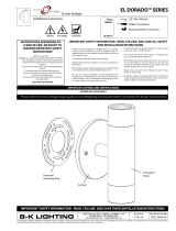
Round UPM mounting plate with CamLock™ assembly
UPM faceplate
UPM housing
Universal mounting ring
Patented 1/2” NPT knockouts*
* UPM is covered in whole or in part by US patent #6,940,012
NEEDED
FOR
INSTALLATION:
By Others
Warning High Voltage Hot Surface
PM2RM ROUND CAMLOCK™ Driver Housing
Constant Current Driver
• Product must be installed by a qualified person in a manner
consistent with its intended use and in compliance with the
National Electrical Code, Canadian Electrical Code, and all Local
and Provincial Codes.
• Follow product label information and instructions.
• Qualified Personnel must perform all servicing or relamping of
this product.
• Before wiring to power supply and during servicing or relamping,
turn off power at fuse or circuit breaker before service.
• The use of accessory equipment not recommended by the
manufacturer or installed contrary to instructions may cause an
unsafe condition. The use of damaged components may cause
an unsafe condition and void product warranty.
IMPORTANT SAFETY INFORMATION - READ, FOLLOW, AND SAVE ALL SAFETY
AND INSTALLATION INSTRUCTIONS
• Do not block light emanating from product in whole or part,
as this may cause an unsafe condition.
• Never operate the fixture with missing or damaged lens.
Lens must be cleaned on regular basis.
• Entire fixture may become extremely hot. Do not touch hot
lens or fixture body. Do not touch the lamp at any time. Use
a clean, dry, soft cloth to handle the lamp. Oil from skin may
damage the lamp and cause it to rupture.
• Replace lamp only with correct wattage and type of lamp
marked on fixture label.
• All gaskets, o-rings and sealing surfaces must be kept clean
during installation and service; failure to do this may cause an
unsafe condition and void product warranty.
INSTRUCTIONS PERTAINING TO
A RISK OF FIRE, OR INJURY TO
PERSONS IMPORTANT SAFETY
INSTRUCTIONS
Lighted lamp is HOT!
WARNING - To reduce the risk of FIRE OR INJURY TO PERSONS:
Turn off/unplug and allow to cool before replacing lamp.
Lamp gets HOT quickly! Contact only switch/plug when
turning on.
Do not touch hot lens, guard, or enclosure (see diagram/
picture).
Keep lamp away from materials that may burn.
Do no touch the lamp at any time. Use a soft cloth. Oil
from skin may damage lamp.
Do not operate the luminaire fitting with a missing or
damaged shield.
SAVE THESE INSTRUCTIONS
· Suitable for wet locations · Additionally suitable for mounting within 4 ft. of the ground
IMPORTANT LISTINGS AND CERTIFICATIONS
REMOTE WIRING
LED Driver
Remote driver installations require inter-connected
wiring between the LED and driver (by others).
Drivers have specific wiring requirements between
these components. Driver manufacturers regularly
recommend the following wiring details for such
installations:
• Do not exceed 50 foot overall wiring distance
using 12 gauge copper wire.
Failure to comply with specific wiring
requirements will void product warranty.

REVISION DATE
12-13-11
REFERENCE NUMBER
INS000795.7
40429 Brickyard Drive • Madera, CA 93636 • USA
559.438.5800 • FAX 559.438.5900
www.bklighting.com • [email protected]
B-K LIGHTING
GroundHotNeutral
A
B
5. Feed branch circuit wiring into UPM housing.
Install housing on CamLock™ at 90° to finished
orientation as shown. (Figure A)
6. Rotate housing 90° counter-clockwise (Figure
B). Tighten set screw with 5/64” allen wrench
on outside of UPM housing to lock in place.
(Figure C)
7. If UPM housing is not level, remove UPM housing;
loosen but DO NOT REMOVE (2) #8-32 screws
with 9/64” allen wrench on CamLock™ assembly.
Adjust CamLock™ assembly up to 30° as needed
to level. Tighten the screws and reattach UPM
housing.
9. Use wire connectors (By Others) to connect driver
primary leads to branch circuit wires. Connect
incoming ground and driver ground to ground
wire provided in UPM housing. See wiring
diagram.
11. Make sure UPM housing gasket is free of any
dirt or debris. Attach the faceplate by tightening
the (4) #6-32 captive screws evenly to 6-9 in/lbs
using a 5/64” allen wrench.
LAMP
BLUE
WHITE
QUICK DISCONNECT
LINE (BLACK)
NEUTRAL (WHITE)
GROUND (GREEN)
BARE WIRE
IN UPM
RED
BLACK
BLUE
WHITE
GREEN
DRIVER
Wiring Diagram.
10. Pull lamp leads into UPM housing and connect
to driver secondary leads using approved wire
connectors (By Others).
NOTE: See driver warning on page 1. Failure
to comply with wiring requirements will void
warranty.
8. Attach tether wire under screw head at the base
of the UPM housing. Slowly lower the faceplate
until tether is taut.
NOTE: Faceplate tether supplied with UPM
is designed as an installation aid and NOT a
safety cable. Do not add weight to, or drop
faceplate.
4. Feed branch circuit wiring and lamp leads to
remote mounted fixture through mounting
plate with CamLock™ assembly. Attach
mounting plate with supplied (2) #10-24
stainless steel hex drive fasteners to universal
ring using 1/8” allen wrench.
IMPORTANT SAFETY INFORMATION LISTED ON REVERSE
READ, FOLLOW, AND SAVE ALL SAFETY AND INSTALLATION INSTRUCTIONS
ETL LISTED
CONFORMS TO ANSI/UL
STANDARD 1598
CERTIFIED TO CAN/CSA
STANDARD C22.2 NO. 250
1. Install standard 4” octagonal/round recessed
junction box in the final fixture location according
to designed lighting plan.
2. Pull branch circuit wiring necessary for installation
(By Others.)
3. Install universal mounting ring.
IMPORTANT! Orientation of universal ring
will affect orientation of UPM! Take note of
mounting plate holes (indicated with arrows)
on the universal ring holes to mount UPM in
correct orientation.
PM2RM ROUND CAMLOCK™ Driver Housing
Constant Current Driver
Horizontal
Vertical

REVISION DATE
12-13-11
REFERENCE NUMBER
INS000795.8
40429 Brickyard Drive • Madera, CA 93636 • USA
559.438.5800 • FAX 559.438.5900
www.bklighting.com • [email protected]
B-K LIGHTING
THIS DOCUMENT CONTAINS PROPRIETARY INFORMATION OF B-K LIGHTING, INC. AND ITS RECEIPT OR POSSESSION DOES NOT CONVEY ANY RIGHTS TO REPRODUCE, DISCLOSE ITS CONTENTS, OR TO MANUFACTURE, USE OR SELL ANYTHING IT MAY
DESCRIBE. REPRODUCTION, DISCLOSURE OR USE WITHOUT SPECIFIC WRITTEN AUTHORIZATION OF B-K LIGHTING, INC. IS STRICTLY FORBIDDEN.
Rectangular UPM mounting plate with CamLock™ assembly
Patented 1/2” NPT knockouts*
UPM housing
UPM faceplate
* UPM is covered in whole or in part by US patent #6,940,012
NEEDED
FOR
INSTALLATION:
By Others
Warning High Voltage Hot Surface
5/64” & 9/64” allen wrench
Wire connectors
Phillips screwdriver
Level
PM2RM RECTANGULAR CAMLOCK™ Driver Housing
Constant Current Driver
• Product must be installed by a qualified person in a manner
consistent with its intended use and in compliance with the
National Electrical Code, Canadian Electrical Code, and all Local
and Provincial Codes.
• Follow product label information and instructions.
• Qualified Personnel must perform all servicing or relamping of
this product.
• Before wiring to power supply and during servicing or relamping,
turn off power at fuse or circuit breaker before service.
• The use of accessory equipment not recommended by the
manufacturer or installed contrary to instructions may cause an
unsafe condition. The use of damaged components may cause
an unsafe condition and void product warranty.
IMPORTANT SAFETY INFORMATION - READ, FOLLOW, AND SAVE ALL SAFETY
AND INSTALLATION INSTRUCTIONS
• Do not block light emanating from product in whole or part,
as this may cause an unsafe condition.
• Never operate the fixture with missing or damaged lens.
Lens must be cleaned on regular basis.
• Entire fixture may become extremely hot. Do not touch hot
lens or fixture body. Do not touch the lamp at any time. Use
a clean, dry, soft cloth to handle the lamp. Oil from skin may
damage the lamp and cause it to rupture.
• Replace lamp only with correct wattage and type of lamp
marked on fixture label.
• All gaskets, o-rings and sealing surfaces must be kept clean
during installation and service; failure to do this may cause an
unsafe condition and void product warranty.
INSTRUCTIONS PERTAINING TO
A RISK OF FIRE, OR INJURY TO
PERSONS IMPORTANT SAFETY
INSTRUCTIONS
Lighted lamp is HOT!
WARNING - To reduce the risk of FIRE OR INJURY TO PERSONS:
Turn off/unplug and allow to cool before replacing lamp.
Lamp gets HOT quickly! Contact only switch/plug when
turning on.
Do not touch hot lens, guard, or enclosure (see diagram/
picture).
Keep lamp away from materials that may burn.
Do no touch the lamp at any time. Use a soft cloth. Oil
from skin may damage lamp.
Do not operate the luminaire fitting with a missing or
damaged shield.
SAVE THESE INSTRUCTIONS
· Suitable for wet locations
IMPORTANT LISTINGS AND CERTIFICATIONS
REMOTE WIRING
LED Driver
Remote driver installations require inter-connected
wiring between the LED and driver (by others).
Drivers have specific wiring requirements between
these components. Driver manufacturers regularly
recommend the following wiring details for such
installations:
• Do not exceed 50 foot overall wiring distance
using 12 gauge copper wire.
Failure to comply with specific wiring
requirements will void product warranty.

7. Attach tether wire under screw head at the base
of the UPM housing and tighten. Slowly lower
the faceplate until tether is taut.
NOTE: Faceplate tether supplied with UPM
is designed as an installation aid and NOT a
safety cable. Do not add weight to, or drop
faceplate.
REVISION DATE
12-13-11
REFERENCE NUMBER
INS000795.8
40429 Brickyard Drive • Madera, CA 93636 • USA
559.438.5800 • FAX 559.438.5900
www.bklighting.com • [email protected]
B-K LIGHTING
GroundHotNeutral
LAMP
BLUE
WHITE
QUICK DISCONNECT
LINE (BLACK)
NEUTRAL (WHITE)
GROUND (GREEN)
BARE WIRE
IN UPM
RED
BLACK
BLUE
WHITE
GREEN
DRIVER
6. If UPM housing is not level, remove UPM housing;
loosen but DO NOT REMOVE (2) #8-32 screws
with 9/64” allen wrench on CamLock™ assembly.
Adjust CamLock™ assembly up to 30° as needed
to level. Tighten the screws and reattach UPM
housing.
8. Use wire connectors (By Others) to connect driver
primary leads to branch circuit wires. Connect
incoming ground and driver ground to ground
wire provided in UPM housing. See wiring
diagram.
10. Make sure UPM housing gasket is free of any dirt
or debris. Attach the faceplate by tightening the
(4) #6-32 captive screws evenly to 6-9 in/lbs using
a 5/64” allen wrench.
A
BC
1. Install standard 4.5” x 2.85” recessed junction box
(by others) in the final fixture location according
to designed lighting plan.
NOTE: Vertical or horizontal installation of
recessed junction box determines orientation
of UPM.
2. Pull branch circuit wiring necessary for installation
(By Others.)
3. Feed branch circuit wiring and lamp leads to
remote mounted fixture through mounting plate
with CamLock™ assembly. Attach mounting plate
with supplied (2) #6-32 stainless steel hex drive
fasteners to recessed junction box using a 5/64”
allen wrench.
4. Feed wire into UPM housing. Install housing
on CamLock™ at 90° to finished orientation as
shown. (Figure A)
5. Rotate housing 90° counter-clockwise (Figure
B). Tighten set screw with 5/64” allen wrench
on outside of UPM housing to lock in place.
(Figure C)
Wiring Diagram.
9. Pull lamp leads into UPM housing and connect
to driver secondary leads using approved wire
connectors (By Others).
NOTE: See driver warning on page 1. Failure
to comply with wiring requirements will void
warranty.
IMPORTANT SAFETY INFORMATION LISTED ON REVERSE
READ, FOLLOW, AND SAVE ALL SAFETY AND INSTALLATION INSTRUCTIONS
ETL LISTED
CONFORMS TO ANSI/UL
STANDARD 1598
CERTIFIED TO CAN/CSA
STANDARD C22.2 NO. 250
PM2RM RECTANGULAR CAMLOCK™ Driver Housing
Constant Current Driver

REVISION DATE
12-13-11
REFERENCE NUMBER
INS000795.9
40429 Brickyard Drive • Madera, CA 93636 • USA
559.438.5800 • FAX 559.438.5900
www.bklighting.com • [email protected]
B-K LIGHTING
THIS DOCUMENT CONTAINS PROPRIETARY INFORMATION OF B-K LIGHTING, INC. AND ITS RECEIPT OR POSSESSION DOES NOT CONVEY ANY RIGHTS TO REPRODUCE, DISCLOSE ITS CONTENTS, OR TO MANUFACTURE, USE OR SELL ANYTHING IT MAY
DESCRIBE. REPRODUCTION, DISCLOSURE OR USE WITHOUT SPECIFIC WRITTEN AUTHORIZATION OF B-K LIGHTING, INC. IS STRICTLY FORBIDDEN.
Mounting brackets
UPM housing
Patented 1/2” NPT knockouts*
UPM faceplate
* UPM is covered in whole or in part by US patent #6,940,012
Warning High Voltage Hot Surface
PM2RM SURFACE MOUNT Driver Housing
Constant Current Driver
5/64” allen wrench
Wire connectors
Hammer
Phillips screwdriver
1/4” drill bit and drill
Mounting hardware
NEEDED
FOR
INSTALLATION:
• Product must be installed by a qualified person in a manner
consistent with its intended use and in compliance with the
National Electrical Code, Canadian Electrical Code, and all Local
and Provincial Codes.
• Follow product label information and instructions.
• Qualified Personnel must perform all servicing or relamping of
this product.
• Before wiring to power supply and during servicing or relamping,
turn off power at fuse or circuit breaker before service.
• The use of accessory equipment not recommended by the
manufacturer or installed contrary to instructions may cause an
unsafe condition. The use of damaged components may cause
an unsafe condition and void product warranty.
IMPORTANT SAFETY INFORMATION - READ, FOLLOW, AND SAVE ALL SAFETY
AND INSTALLATION INSTRUCTIONS
• Do not block light emanating from product in whole or part,
as this may cause an unsafe condition.
• Never operate the fixture with missing or damaged lens.
Lens must be cleaned on regular basis.
• Entire fixture may become extremely hot. Do not touch hot
lens or fixture body. Do not touch the lamp at any time. Use
a clean, dry, soft cloth to handle the lamp. Oil from skin may
damage the lamp and cause it to rupture.
• Replace lamp only with correct wattage and type of lamp
marked on fixture label.
• All gaskets, o-rings and sealing surfaces must be kept clean
during installation and service; failure to do this may cause an
unsafe condition and void product warranty.
INSTRUCTIONS PERTAINING TO
A RISK OF FIRE, OR INJURY TO
PERSONS IMPORTANT SAFETY
INSTRUCTIONS
Lighted lamp is HOT!
WARNING - To reduce the risk of FIRE OR INJURY TO PERSONS:
Turn off/unplug and allow to cool before replacing lamp.
Lamp gets HOT quickly! Contact only switch/plug when
turning on.
Do not touch hot lens, guard, or enclosure (see diagram/
picture).
Keep lamp away from materials that may burn.
Do no touch the lamp at any time. Use a soft cloth. Oil
from skin may damage lamp.
Do not operate the luminaire fitting with a missing or
damaged shield.
SAVE THESE INSTRUCTIONS
· Suitable for wet locations
IMPORTANT LISTINGS AND CERTIFICATIONS
REMOTE WIRING
LED Driver
Remote driver installations require inter-connected
wiring between the LED and driver (by others).
Drivers have specific wiring requirements between
these components. Driver manufacturers regularly
recommend the following wiring details for such
installations:
• Do not exceed 50 foot overall wiring distance
using 12 gauge copper wire.
Failure to comply with specific wiring
requirements will void product warranty.

REVISION DATE
12-13-11
REFERENCE NUMBER
INS000795.9
40429 Brickyard Drive • Madera, CA 93636 • USA
559.438.5800 • FAX 559.438.5900
www.bklighting.com • [email protected]
B-K LIGHTING
4. Attach the UPM housing at mounting brackets
with ¼” fasteners (by others). Use suitable
mounting hardware for surface.
NOTE: Many methods exist to bolt to a flat
surface. The fixture is provided with mounting
brackets with ¼” holes.
5. Connect 1/2” conduit connector through female
threaded conduit entry.
NOTE: Surface conduit is a common entrance
for water if not properly sealed. Seal connector
threads and conduit with a suitable sealant
(Teflon tape, adhesive, etc.). Sealing the
conduit after knockouts are removed is
required to maintain warranty.
6. Pull branch circuit wiring necessary for
installation (By Others.)
7. Attach tether wire under screw head at the base
of the UPM housing and tighten. Slowly lower
the faceplate until tether is taut.
NOTE: Faceplate tether supplied with UPM
is designed as an installation aid and NOT a
safety cable. Do not add weight to, or drop
faceplate.
GroundHotNeutral
LAMP
BLUE
WHITE
QUICK DISCONNECT
LINE (BLACK)
NEUTRAL (WHITE)
GROUND (GREEN)
BARE WIRE
IN UPM
RED
BLACK
BLUE
WHITE
GREEN
DRIVER
8. Use wire connectors (By Others) to connect driver
primary leads to branch circuit wires. Connect
incoming ground and driver ground to ground
wire provided in UPM housing. See wiring
diagram.
Wiring Diagram.
9. Pull lamp leads into UPM housing and connect
to driver secondary leads using approved wire
connectors (By Others).
NOTE: See driver warning on page 1. Failure
to comply with wiring requirements will
void warranty.
IMPORTANT SAFETY INFORMATION LISTED ON REVERSE
READ, FOLLOW, AND SAVE ALL SAFETY AND INSTALLATION INSTRUCTIONS
ETL LISTED
CONFORMS TO ANSI/UL
STANDARD 1598
CERTIFIED TO CAN/CSA
STANDARD C22.2 NO. 250
PM2RM SURFACE MOUNT Driver Housing
Constant Current Driver
1. Place provided template in final mounting
position according to designed lighting plan.
NOTE: Additional templates are available at
http://www.bklighting.com/templates
2. Drill holes into surface for ¼” fasteners (by
others) on locations illustrated on template.
3. Remove Patented Knockout(s) as necessary from
the inside of the UPM housing for branch circuit
wiring and lamp leads to remote mounted
fixture. Leave remaining unused knockouts in
place to maintain seal.
NOTE: Patented design featuring a silicone ‘O’
Ring allowing knockout to be tapped back into
place to renew seal integrity.

REVISION DATE
12-13-11
REFERENCE NUMBER
INS000795.9
40429 Brickyard Drive • Madera, CA 93636 • USA
559.438.5800 • FAX 559.438.5900
www.bklighting.com • [email protected]
B-K LIGHTING
10. Make sure UPM housing gasket is free of any dirt
or debris. Attach the faceplate by tightening the
(4) #6-32 captive screws evenly to 6-9 in/lbs using
a 5/64” allen wrench.
IMPORTANT SAFETY INFORMATION LISTED ON REVERSE
READ, FOLLOW, AND SAVE ALL SAFETY AND INSTALLATION INSTRUCTIONS
ETL LISTED
CONFORMS TO ANSI/UL
STANDARD 1598
CERTIFIED TO CAN/CSA
STANDARD C22.2 NO. 250
PM2RM SURFACE MOUNT Driver Housing
Constant Current Driver

DRAWING NUMBER
PM2 SURFACE TEMPLATE
THIS DOCUMENT CONTAINS PROPRIETARY INFORMATION OF B-K LIGHTING AND ITS RECEIPT OR POSSESSION
DOES NOT CONVEY ANY RIGHTS TO REPRODUCE, DISCLOSE ITS CONTENTS, OR TO MANUFACTURE, USE OR
SELL ANYTHING IT MAY DESCRIBE. REPRODUCTION, DISCLOSURE OR USE WITHOUT SPECIFIC WRITTEN
AUTHORIZATION OF B-K LIGHTING IS STRICTLY FORBIDDEN.
NOTES:
1.
THE SMALL CIRCLES ARE THE LOCATION OF THE 1/4" FASTENERS (BY OTHERS) REQUIRED FOR FINISHED MOUNTING.
8
5/8
"
1
3/4
"
WARNING!
Template must print at proper scale.
Verify dimensions prior to use.
12/22/06
INS-1503
/