Page is loading ...

Matrix 3200 and 6400 Series
Video Switcher
68-355-04 Rev. E
Printed in the USA
11 02
MATRIX 6400
WIDEBAND VIDEO
POWER SUPPLIES COMMUNICATIONS
PRIMARY TX
RS232 BME REMOTE
SYSTEM
STATUS
REDUNDANT RX
DIAGNOSTICS
+
V
-
V
MATRIX 6400
WIDEBAND VIDEO
POWER SUPPLIES COMMUNICATIONS
PRIMARY TX
RS232 BME REMOTE
SYSTEM
STATUS
REDUNDANT RX
DIAGNOSTICS
+
V
-
V
MATRIX 6400
SYNC
POWER SUPPLIES COMMUNICATIONS
PRIMARY TX
RS232 BME REMOTE
SYSTEM
STATUS
REDUNDANT RX
DIAGNOSTICS
+
V
-
V
MATRIX 6400
SYNC
POWER SUPPLIES COMMUNICATIONS
PRIMARY TX
RS232 BME REMOTE
SYSTEM
STATUS
REDUNDANT RX
DIAGNOSTICS
+
V
-
V
MATRIX 6400
SYNC
POWER SUPPLIES COMMUNICATIONS
PRIMARY TX
RS232 BME REMOTE
SYSTEM
STATUS
REDUNDANT RX
DIAGNOSTICS
+
V
-
V
RGB
MUTE
AUDIO
MUTE
FPC-1000
MATRIX 6400
AUDIO
POWER SUPPLIES COMMUNICATIONS
PRIMARY TX
RS232 BME REMOTE
SYSTEM
STATUS
REDUNDANT RX
DIAGNOSTICS
+
V
-
V
RGB
MUTE
AUDIO
MUTE
FPC-1000
MATRIX 6400
AUDIO
POWER SUPPLIES COMMUNICATIONS
PRIMARY TX
RS232 BME REMOTE
SYSTEM
STATUS
REDUNDANT RX
DIAGNOSTICS
+
V
-
V

This symbol is intended to alert the user of important operating and maintenance
(servicing) instructions in the literature provided with the equipment.
This symbol is intended to alert the user of the presence of uninsulated dangerous
voltage within the product's enclosure that may present a risk of electric shock.
Caution
Read Instructions • Read and understand all safety and operating instructions before using the
equipment.
Retain Instructions • The safety instructions should be kept for future reference.
Follow Warnings • Follow all warnings and instructions marked on the equipment or in the user
information.
Avoid Attachments • Do not use tools or attachments that are not recommended by the equipment
manufacturer because they may be hazardous.
Warning
Power sources • This equipment should be operated only from the power source indicated on the
product. This equipment is intended to be used with a main power system with a grounded
(neutral) conductor. The third (grounding) pin is a safety feature, do not attempt to bypass or
disable it.
Power disconnection • To remove power from the equipment safely, remove all power cords from
the rear of the equipment, or the desktop power module (if detachable), or from the power
source receptacle (wall plug).
Power cord protection • Power cords should be routed so that they are not likely to be stepped on or
pinched by items placed upon or against them.
Servicing • Refer all servicing to qualified service personnel. There are no user-serviceable parts
inside. To prevent the risk of shock, do not attempt to service this equipment yourself because
opening or removing covers may expose you to dangerous voltage or other hazards.
Slots and openings • If the equipment has slots or holes in the enclosure, these are provided to
prevent overheating of sensitive components inside. These openings must never be blocked by
other objects.
Lithium battery • There is a danger of explosion if battery is incorrectly replaced. Replace it only
with the same or equivalent type recommended by the manufacturer. Dispose of used batteries
according to the manufacturer's instructions.
Ce symbole sert à avertir l’utilisateur que la documentation fournie avec le matériel
contient des instructions importantes concernant l’exploitation et la maintenance
(réparation).
Ce symbole sert à avertir l’utilisateur de la présence dans le boîtier de l’appareil de
tensions dangereuses non isolées posant des risques d’électrocution.
Attention
Lire les instructions• Prendre connaissance de toutes les consignes de sécurité et d’exploitation avant
d’utiliser le matériel.
Conserver les instructions• Ranger les consignes de sécurité afin de pouvoir les consulter à l’avenir.
Respecter les avertissements • Observer tous les avertissements et consignes marqués sur le matériel ou
présentés dans la documentation utilisateur.
Eviter les pièces de fixation • Ne pas utiliser de pièces de fixation ni d’outils non recommandés par le
fabricant du matériel car cela risquerait de poser certains dangers.
Avertissement
Alimentations• Ne faire fonctionner ce matériel qu’avec la source d’alimentation indiquée sur
l’appareil. Ce matériel doit être utilisé avec une alimentation principale comportant un fil de
terre (neutre). Le troisième contact (de mise à la terre) constitue un dispositif de sécurité :
n’essayez pas de la contourner ni de la désactiver.
Déconnexion de l’alimentation• Pour mettre le matériel hors tension sans danger, déconnectez tous
les cordons d’alimentation de l’arrière de l’appareil ou du module d’alimentation de bureau (s’il
est amovible) ou encore de la prise secteur.
Protection du cordon d’alimentation • Acheminer les cordons d’alimentation de manière à ce que
personne ne risque de marcher dessus et à ce qu’ils ne soient pas écrasés ou pincés par des
objets.
Réparation-maintenance • Faire exécuter toutes les interventions de réparation-maintenance par un
technicien qualifié. Aucun des éléments internes ne peut être réparé par l’utilisateur. Afin
d’éviter tout danger d’électrocution, l’utilisateur ne doit pas essayer de procéder lui-même à ces
opérations car l’ouverture ou le retrait des couvercles risquent de l’exposer à de hautes tensions
et autres dangers.
Fentes et orifices • Si le boîtier de l’appareil comporte des fentes ou des orifices, ceux-ci servent à
empêcher les composants internes sensibles de surchauffer. Ces ouvertures ne doivent jamais
être bloquées par des objets.
Lithium Batterie • Il a danger d'explosion s'll y a remplacment incorrect de la batterie. Remplacer
uniquement avec une batterie du meme type ou d'un ype equivalent recommande par le
constructeur. Mettre au reut les batteries usagees conformement aux instructions du fabricant.
Safety Instructions • English
Consignes de Sécurité • Français
Sicherheitsanleitungen • Deutsch
Dieses Symbol soll dem Benutzer in der im Lieferumfang enthaltenen
Dokumentation besonders wichtige Hinweise zur Bedienung und Wartung
(Instandhaltung) geben.
Dieses Symbol soll den Benutzer darauf aufmerksam machen, daß im Inneren des
Gehäuses dieses Produktes gefährliche Spannungen, die nicht isoliert sind und
die einen elektrischen Schock verursachen können, herrschen.
Achtung
Lesen der Anleitungen • Bevor Sie das Gerät zum ersten Mal verwenden, sollten Sie alle Sicherheits-und
Bedienungsanleitungen genau durchlesen und verstehen.
Aufbewahren der Anleitungen • Die Hinweise zur elektrischen Sicherheit des Produktes sollten Sie
aufbewahren, damit Sie im Bedarfsfall darauf zurückgreifen können.
Befolgen der Warnhinweise • Befolgen Sie alle Warnhinweise und Anleitungen auf dem Gerät oder in
der Benutzerdokumentation.
Keine Zusatzgeräte • Verwenden Sie keine Werkzeuge oder Zusatzgeräte, die nicht ausdrücklich vom
Hersteller empfohlen wurden, da diese eine Gefahrenquelle darstellen können.
Vorsicht
Stromquellen • Dieses Gerät sollte nur über die auf dem Produkt angegebene Stromquelle betrieben
werden. Dieses Gerät wurde für eine Verwendung mit einer Hauptstromleitung mit einem
geerdeten (neutralen) Leiter konzipiert. Der dritte Kontakt ist für einen Erdanschluß, und stellt
eine Sicherheitsfunktion dar. Diese sollte nicht umgangen oder außer Betrieb gesetzt werden.
Stromunterbrechung • Um das Gerät auf sichere Weise vom Netz zu trennen, sollten Sie alle
Netzkabel aus der Rückseite des Gerätes, aus der externen Stomversorgung (falls dies möglich
ist) oder aus der Wandsteckdose ziehen.
Schutz des Netzkabels • Netzkabel sollten stets so verlegt werden, daß sie nicht im Weg liegen und
niemand darauf treten kann oder Objekte darauf- oder unmittelbar dagegengestellt werden
können.
Wartung • Alle Wartungsmaßnahmen sollten nur von qualifiziertem Servicepersonal durchgeführt
werden. Die internen Komponenten des Gerätes sind wartungsfrei. Zur Vermeidung eines
elektrischen Schocks versuchen Sie in keinem Fall, dieses Gerät selbst öffnen, da beim Entfernen
der Abdeckungen die Gefahr eines elektrischen Schlags und/oder andere Gefahren bestehen.
Schlitze und Öffnungen • Wenn das Gerät Schlitze oder Löcher im Gehäuse aufweist, dienen diese
zur Vermeidung einer Überhitzung der empfindlichen Teile im Inneren. Diese Öffnungen dürfen
niemals von anderen Objekten blockiert werden.
Litium-Batterie • Explosionsgefahr, falls die Batterie nicht richtig ersetzt wird. Ersetzen Sie
verbrauchte Batterien nur durch den gleichen oder einen vergleichbaren Batterietyp, der auch
vom Hersteller empfohlen wird. Entsorgen Sie verbrauchte Batterien bitte gemäß den
Herstelleranweisungen.
Este símbolo se utiliza para advertir al usuario sobre instrucciones importantes de
operación y mantenimiento (o cambio de partes) que se desean destacar en el
contenido de la documentación suministrada con los equipos.
Este símbolo se utiliza para advertir al usuario sobre la presencia de elementos con
voltaje peligroso sin protección aislante, que puedan encontrarse dentro de la caja
o alojamiento del producto, y que puedan representar riesgo de electrocución.
Precaucion
Leer las instrucciones • Leer y analizar todas las instrucciones de operación y seguridad, antes de usar
el equipo.
Conservar las instrucciones • Conservar las instrucciones de seguridad para futura consulta.
Obedecer las advertencias • Todas las advertencias e instrucciones marcadas en el equipo o en la
documentación del usuario, deben ser obedecidas.
Evitar el uso de accesorios • No usar herramientas o accesorios que no sean especificamente
recomendados por el fabricante, ya que podrian implicar riesgos.
Advertencia
Alimentación eléctrica • Este equipo debe conectarse únicamente a la fuente/tipo de alimentación
eléctrica indicada en el mismo. La alimentación eléctrica de este equipo debe provenir de un
sistema de distribución general con conductor neutro a tierra. La tercera pata (puesta a tierra) es
una medida de seguridad, no puentearia ni eliminaria.
Desconexión de alimentación eléctrica • Para desconectar con seguridad la acometida de
alimentación eléctrica al equipo, desenchufar todos los cables de alimentación en el panel trasero
del equipo, o desenchufar el módulo de alimentación (si fuera independiente), o desenchufar el
cable del receptáculo de la pared.
Protección del cables de alimentación • Los cables de alimentación eléctrica se deben instalar en
lugares donde no sean pisados ni apretados por objetos que se puedan apoyar sobre ellos.
Reparaciones/mantenimiento • Solicitar siempre los servicios técnicos de personal calificado. En el
interior no hay partes a las que el usuario deba acceder. Para evitar riesgo de electrocución, no
intentar personalmente la reparación/mantenimiento de este equipo, ya que al abrir o extraer las
tapas puede quedar expuesto a voltajes peligrosos u otros riesgos.
Ranuras y aberturas • Si el equipo posee ranuras o orificios en su caja/alojamiento, es para evitar el
sobrecalientamiento de componentes internos sensibles. Estas aberturas nunca se deben obstruir
con otros objetos.
Batería de litio • Existe riesgo de explosión si esta batería se coloca en la posición incorrecta. Cambiar
esta batería únicamente con el mismo tipo (o su equivalente) recomendado por el fabricante.
Desachar las baterías usadas siguiendo las instrucciones del fabricante.
Instrucciones de seguridad • Español
Precautions

Chapter 1 - Introduction to the Matrix 3200/6400 Video Switcher
What is a Matrix 3200/6400 Video Switcher?...................................................................................... 1-1
Features ...................................................................................................................................... 1-1
Feature Descriptions ....................................................................................................................1-2
Matrix 3200 & 6400 Video Switchers - Description and Options..........................................................1-3
Matrix 3200/6400 System Manuals.............................................................................................. 1-4
Matrix 3200/6400 Video Switcher System Overview........................................................................... 1-5
Matrix 3200 Video and Matrix 6400 Audio Switcher System.........................................................1-6
Specifications .................................................................................................................................... 1-7
Chapter 2 - Installing the Matrix 3200/6400 Video Switcher
Matrix 3200/6400 Video Switcher Installation ..................................................................................... 2-1
Installing BME(s) ......................................................................................................................... 2-1
Setting BME Addresses .............................................................................................................. 2-2
Connecting the BME COMM Interconnecting Cable(s) .................................................................2-2
Connecting the RS-232/RS-422 Cable to BME #0........................................................................ 2-2
Connecting the External Vertical Interval Sync Cables................................................................. 2-2
Connecting the AC Power Cable(s) to the BME(s)........................................................................ 2-2
Applying AC Power to the BME(s) ............................................................................................... 2-2
BME Power-Up Verification .......................................................................................................... 2-3
Installing the Matrix 6400/3200 Virtualization/Control Program Software ......................................2-4
Virtualizing the Matrix 3200/6400 Switcher/System ..................................................................... 2-4
Matrix 3200/6400 Video Input/Output Cabling .............................................................................. 2-4
Chapter 3 - Using the Matrix 6400 System Virtualization/Control Software
Extron’s Matrix 3200/6400 System Virtualization/Control Program ..................................................... 3-1
An Explanation of VIRTUAL I/O SWITCHING in the Matrix 3200/6400 System .................................. 3-1
Creating a VIRTUAL I/O SWITCHING SYSTEM (MAP) for the Matrix 3200/6400 System.................. 3-2
How to Create ROOMS within the Matrix 43200/6400 System ........................................................... 3-6
How to REMOTE CONTROL PROGRAM the Matrix 3200/6400 System ............................................ 3-7
How to OFF-LINE (Emulate) PROGRAM the Matrix 3200/6400 System............................................. 3-8
How to SAVE and RESTORE the Matrix 3200/6400 Settings ........................................................... 3-10
How to Create PROGRAM BYTE STRINGS for the Matrix 3200/6400 System ................................ 3-10
Chapter 4 - RS-232 / RS-422 Programmer's Guide
Serial Communications Port............................................................................................................... 4-1
Host to Switcher Communications......................................................................................................4-2
Command/Response Table .................................................................................................................4-2
Symbol definitions ....................................................................................................................... 4-3
Simple Instruction Set Commands............................................................................................... 4-3
Advanced Instruction Set and Simple Instruction Set Commands ...............................................4-6
Error Codes with Descriptions ......................................................................................................4-8
Switcher Generated Unsolicited Responses................................................................................. 4-8
Chapter 5 - Upgrades and Troubleshooting
Upgrade and Troubleshooting Procedures ...........................................................................................5-1
Adding a Front Panel Controller to an Existing System ................................................................ 5-1
BME Internal Access...................................................................................................................5-2
Installing a Software Update............................................................................................................... 5-3
Swapping RS-232 / RS-422 Ports.......................................................................................................5-4
Troubleshooting a Matrix 3200/6400 System Problem ........................................................................ 5-5
Matrix 3200/6400 Video Switcher Upgrade - Changing the Matrix Size ...............................................5-7
Adding BME(s) to a Matrix 3200/6400 System................................................................................... 5-9
Software Procedure - Before and After a Hardware Upgrade............................................................. 5-11
Appendix A - Reference Information
Matrix 3200/6400 Series Part Numbers ............................................................................................. A-1
Binary/Hex/Decimal Conversion Table ............................................................................................... A-5
Contents
i

Glossary of Terms ............................................................................................................................. A-6
Matrix 3200 & 6400 Video Switcher Virtualization Work-sheets ....................................................... A-11
Safety Instructions..................................................................................................... Inside Front Cover
Warranty..................................................................................................................... Inside Back Cover
The following icons may be used in this manual:
______ Important information – for example, an action or a step that must be done
before proceeding.
______ A Warning – possible dangerous voltage present.
______ A Warning – possible damage could occur.
____ A Note, a Hint, or a Tip that may be helpful.
_____ Possible Electrostatic Discharge (ESD) damage could result from touching
electronic components.
_____ Indicates word definitions. Additional information may be referenced in another
section, or in another document.
Written and Printed in the USA
Matrix 3200/6400 Video Switcher
User's Manual
68-355-04
Rev. Ex1
11 02

1
Chapter One
Introduction to the Matrix 3200/6400
Video Switcher
What is a Matrix 3200/6400 Video Switcher?
Features
Specifications
Matrix 3200/6400 Video Switcher

Extron • Matrix 3200/6400 Series • User’s Manual
Chapter 1 • Introduction to the Matrix 3200/6400 Video Switcher
What is a Matrix 3200/6400 Video Switcher?
The Matrix 3200/6400 Video Switchers may be used with composite video,
S-Video and component video. The Switchers are housed in 5U high rack-
mountable metal enclosures with internal universal switching power supplies.
They may be used as stand-alone video switchers or as part of a Matrix 3200/
6400 system switcher.
In most installations an RS-232 program will be used to control the Matrix 3200/
6400 Video Switcher as a stand-alone or as part of a system switcher. Control
can be from any user-supplied controlling device capable of generating the
proper commands such as a PC using Extron’s Windows® control software or
AMX, Crestron, etc. An optional Front Panel Controller enables the user to
perform most configuration operations at the switcher.
See “Matrix 3200 & 6400 Video Switcher System Overview” on Page 1-5.
Features
• Supports Composite video, S-Video and Component video
• Virtual input and output assignments
• Microprocessor Control
• Independent matrix switching outputs
• 32 Global Preset configurations stored in nonvolatile memory
• 10 Room configurations with 10 Presets per room
• RS-232/RS-422 (serial port) control
• Rack mountable metal enclosure with internal Universal Power Supplies
• Redundant power supplies (Optional)
• FPC 1000 Front Panel Controller (Optional)
• MKP 1000 and MCP 1000 remote keypads control switching in remote
rooms (Optional)
1-1
MATRIX 6400
VIDEO
POWER SUPPLIES COMMUNICATIONS
PRIMARY TX
RS232 BME REMOTE
SYSTEM
STATUS
REDUNDANT RX
DIAGNOSTICS
+
V
-
V
FPC-1000
RGB
MUTE
AUDIO
MUTE
Figure 1-1.A Matrix 6400 Video Switcher w/optional FPC 1000

Extron • Matrix 3200/6400 Series • User’s Manual
Chapter 1 • Introduction to the Matrix 3200/6400 Video Switcher
1-2
Feature Descriptions
Virtual Control – Logical assignment of physical Input/Output connector.
Microprocessor Control – A Microprocessor enables the Matrix 3200/6400
Video switcher to be programmed from a host system, or from the optional
Front Panel Controller (FPC 1000).
Global Preset configurations (32 +1 ) – Thirty-two Global Preset
configurations plus the current I/O configuration are stored in nonvolatile
memory. As new configurations are developed, they may be stored as
Global Presets (up to a total of thirty-two) in the Preset memory. Any preset
may later be recalled – instantly setting the switcher to the desired
configuration.
Room configurations – 10 Room configurations with 10 Presets for each
Room enables 10 different remote locations to control switching for that
particular location using an optional MKP 1000 or MCP 1000 Remote
Keypad. Room Configurations may be significantly different from room to
room and would probably only include a select number of inputs and outputs
per room.
Memory – Nonvolatile memory contents remain valid after power is removed
normally or due to a power failure.
RS-232/RS-422– The Matrix 3200/6400 Video Switcher can be controlled by
any remote Host system with serial communications capability.
Rack Mountable metal enclosures – Matrix Video Switchers are housed in
5U high, rack mountable-metal enclosures. An internal switch mode power
supply is standard for all models.
Modular Design – The modular design of the Matrix 3200/6400 Video
Switcher provides flexibility and expandibility by allowing users to purchase
only the modules required for their systems. BMEs may also be upgraded by
adding output video cards (8 outputs/card).
Redundant Power Supply (Optional) – If the main power supply fails, the
Redundant Power Supply will take over automatically.
FPC 1000 Front Panel Controller (Optional) – The FPC 1000 mounts in
place of the blank access panel in the master module (BME #0) and enables
the user to perform most configuration operations at the switcher. See FPC
1000 User’s Manual (Extron Part #68-355-02).
AC POWER INPUT
FUSE: 250V 5.0A TT
IN
OUT
100-240V 5.0A MAX 50/60Hz
DISCONNECT POWER CORD BEFORE SERVICING
MKP COMM.BME COMM. RS232/RS422
A
B
C
D
E
A
B
C
D
E
BME
ADDRESS
ANAHEIM, CA
MADE IN USA
4
-
+
INPUTS OUTPUTS
OUT OUT OUT OUT OUT OUT OUT OUT
1 - 8 9 - 16 17 - 24 25 - 32 33 - 40 41 - 48 49 - 56 57 - 64
1IN
SYNC
OUT
9 172533414957
2 10182634425058
3 11192735435159
4 12202836445260
5 13212937455361
6 14223038465462
7 15233139475563
8 16243240485664
Figure 1-2.A Matrix 6400 Video Switcher (Rear Panel View)

Extron • Matrix 3200/6400 Series • User’s Manual
Chapter 1 • Introduction to the Matrix 3200/6400 Video Switcher
1-3
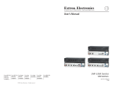
Matrix 6400 Video Switcher
(Front View) - shown with
optional Front Panel Controller
(FPC 1000)
MATRIX 6400
VIDEO
POWER SUPPLIES COMMUNICATIONS
PRIMARY TX
RS232 BME REMOTE
SYSTEM
STATUS
REDUNDANT RX
DIAGNOSTICS
+
V
-
V
FPC-1000
RGB
MUTE
AUDIO
MUTE
Matrix 6400 Video Switcher
(Rear View) - shown with 8
Video Output cards installed.
AC POWER INPUT
FUSE: 250V 5.0A TT
IN
OUT
100-240V 5.0A MAX 50/60Hz
DISCONNECT POWER CORD BEFORE SERVICING
MKP COMM.BME COMM. RS232/RS422
A
B
C
D
E
A
B
C
D
E
BME
ADDRESS
ANAHEIM, CA
MADE IN USA
4
-
+
INPUTS OUTPUTS
OUT OUT OUT OUT OUT OUT OUT OUT
1 - 8 9 - 16 17 - 24 25 - 32 33 - 40 41 - 48 49 - 56 57 - 64
1IN
SYNC
OUT
9 172533414957
2 10182634425058
3 11192735435159
4 12202836445260
5 13212937455361
6 14223038465462
7 15233139475563
8 16243240485664

Extron • Matrix 3200/6400 Series • User’s Manual
Chapter 1 • Introduction to the Matrix 3200/6400 Video Switcher
1-4
Matrix 3200/6400 System Manuals
This manual (68-355-03) covers the Matrix 6400 Audio Switcher. Following is a
list of related manuals:
• 68-355-01 = MKP 1000 User’s Manual
• 68-355-02 = FPC 1000 User’s Manual
• 68-456-01 = MCP 1000 User’s Manual
• 68-355-04 = Matrix 3200 and 6400 Video User’s Manual
• 68-355-05 = Matrix 3200 and 6400 Wideband Video/Sync User’s Manual
Matrix 3200 Switcher
(Rear View) - shown with 4
Video Output cards installed.
Matrix 3200 Video Switcher
(Front View) - shown with a
blank access panel.
MATRIX 6400
AUDIO
POWER SUPPLIES COMMUNICATIONS
PRIMARY TX
RS232 BME REMOTE
SYSTEM
STATUS
REDUNDANT RX
DIAGNOSTICS
+
V
-
V

Extron • Matrix 3200/6400 Series • User’s Manual
Chapter 1 • Introduction to the Matrix 3200/6400 Video Switcher
1-5
Matrix 3200 & 6400 Video Switcher System Overview
A Matrix 3200/6400 Video Switcher System may consist of 1 to 3 Matrix 3200
and/or Matrix 6400 Video BMEs (Basic Module Enclosures). Three video formats
are supported, composite video, S-Video and component video. The switcher
system may be dedicated to any one video format or a combination of all three
formats in almost any configuration. What makes this possible is the switcher’s
unique ability to accept virtual connector assignments of its physical connectors.
Virtual assignments are done through the RS-232 serial port of the switcher from
a Host computer using Extron supplied software. If a system consists of more
than one switcher, the Host computer communicates with the switcher
designated as BME #0 which communicates with the other switcher(s). When
Virtual assignments have been completed, the system is considered to be
Virtualized.
One or more physical input connectors may be assigned as any Virtual input
number, the same is true of the output connectors. Virtual input and output
assignments are done through BME #0’s RS-232/RS-422 communications port
with a PC computer using Extron’s Matrix 3200/6400 System Virtualization/
Control software. This will probably need to be done during initial system
installation (before installing input and output cables) and would not normally
need to be repeated unless the system configuration changed. After the Virtual
inputs and outputs have been assigned (the system has been Virtualized), the
input and output cables are installed. Input/output selection (Ties and/or Presets)
may be done through the RS-232/RS-422 port with a PC Host or from a touch
screen or any other user-supplied controlling device, such as AMX, Creston,
etc., that is capable of generating the proper commands, or, with an optional
FPC 1000 Front Panel Controller.
Figure 1-5.A is an example of a Virtualized Matrix 3200 Video Switcher with 16
S-Video inputs and 4 S-Video outputs. The circles represent BNC connectors,
the physical connector number is shown just outside each circle (one o’clock
position). The Virtual assignment for each connector is shown inside the circle;
for example, physical input connectors 1 and 2 are Virtual input #1 (Y1 and C1).
If Virtual input #1 is tied (switched) to Virtual output #4, the YC video on physical
input connectors 1 and 2 will be output to physical output connectors 7 and 8.
Blank Virtual Matrix work-sheets which may be copied and used to assist in
Virtualizing a system are provided in Appendix A. The Matrix 3200/6400 System
Virtualization/Control software may also be used to print maps which show the
physical connectors to Virtual assignments and make it easy to cable a system.
A Matrix 3200/6400 System Virtualization/Control Software Tutorial with
instructions for Virtualizing a system is provided in Chapter 3 of this manual.
Figure 1-5.A 32x8 Video Switcher BME virtualized for 16x4 S-Video matrix.

Extron • Matrix 3200/6400 Series • User’s Manual
Chapter 1 • Introduction to the Matrix 3200/6400 Video Switcher
1-6
Matrix 3200 Video and Matrix 6400 Audio Switcher System
A Matrix 6400 Video Switcher System may include a Matrix 6400 Audio Switcher
which would enable the system to switch both video and audio. Figure 1-6.A
below is an example of a virtualized 16x8 S-Video configured Matrix 3200 Video
Switcher (top chassis) combined with a 32x8 Matrix 6400 Audio Switcher
(bottom chassis). Audio-follow/breakaway are among the supported features of
mixed video and audio configurations.
Virtualization (mapping) of the sytem in Figure 1-6.A below shows virtual audio
inputs 1 - 16 mapped to follow virtual video inputs 1 - 16. Audio inputs 17 - 32 are
shown mapped as unassigned to specific video inputs but available to all video
inputs. Input to output connections (ties) including audio breakaway may be
made via a Host computer/control device or from an FPC 1000 Front Panel
Controller.
Example 1: Video/Audio Follow
Virtual video input 1 tied to virtual video output 8 and virtual audio input 1 tied to
virtual audio output 8 enables the video and audio (a football game?) from a
Satellite Receiver to be seen and heard with a monitor.
Example 2: Video/Audio Breakaway
Virtual video input 1 tied to virtual video output 8 and virtual audio input 4 tied to
virtual audio output 8 enables the video (a football game?) to be seen while
listening to a CD. This is a typical breakaway audio example.
Example 3: Video/Audio Breakaway
Virtual video input 1 tied to virtual video output 8 and virtual audio input 32 tied
to virtual output 8 enables the video (a football game?) to be seen while listening
to a stereo radio. This example demonstrates breakaway audio using an
unassigned audio input.
Figure 1-6.A Matrix 3200 Video system with Matrix 6400 Audio Switcher.

Extron • Matrix 3200/6400 Series • User’s Manual
Chapter 1 • Introduction to the Matrix 3200/6400 Video Switcher
1-7
Matrix 3200/6400 Video Switcher Specifications
Video input
Number/signal type ............... Up to 32 or 64 (varies with configuration) RGsB, RsGsBs, component video,
S-video, composite video, HDTV
Connectors........................... BNC female (quantity varies with model)
Nominal level ....................... Analog......1V p-p
Minimum/maximum level(s) ... Analog......0.5V to 1.5V p-p
Impedance ........................... 75 ohms
Return loss ........................... –30dB @5 MHz
External sync (genlock)........ 0.3V to 12V p-p, 75 ohms
Video throughput
Routing................................. 16 x 8 or larger matrix up to 32 x 32 or 64 x 64, depending on model and
configuration
Gain ..................................... Unity
Bandwidth — Matrix 6400 .... Minimum .............. 80 MHz (–3dB), fully loaded
Maximum ............. 150 MHz (-3dB), fully loaded
0–10 MHz............. No more than +0.1dB to -0.1dB
0–30 MHz............. No more than +0.5dB to -0.5dB
Crosstalk .............................. > 65dB @ 20 MHz
> 80dB @ 60 MHz
Switching speed ................... 200 nS (max.)
Video output
Number/signal type .............. Up to 32 or 64 (varies with configuration) RGsB, RsGsBs, component video,
S-video, composite video, HDTV
Connectors........................... BNC female (quantity varies with model)
Nominal level ....................... 1V p-p
Impedance ........................... 75 ohms
Return loss ........................... –40dB to input section 3.58 MHz/4.43 MHz
DC offset .............................. ±10mV maximum
Switching type ...................... Vertical interval
Slew rate .............................. >200V/mS
Control/Remote — switcher
Serial control port ................. RS-232 or RS-422, 9-pin female D connector
Baud rate and protocol ......... 9600 , 8-bit, 1 stop bit, no parity
Pin configurations................. 2 = TX, 3 = RX, 5 = GND
System intercommunications 2 RJ-11 connectors
Remote keypad control ......... 2 5 mm, 5-pin captive screw connectors
Program control .................... Extron’s control program for Windows®
Extron’s Simple Instruction Set™ — SIS™
General
Power................................... 100VAC to 240VAC, 50/60 Hz; internal, auto-switchable
Matrix 6400 video........ 90 watts at 115VAC, 60 Hz
Matrix 3200 video........ 40 watts at 115VAC, 60 Hz
Temperature/humidity ........... Storage –40° to +158° F (–40° to +70° C) / 10% to 90%, non-condensing
Operating +32° to +122° F (0° to 50° C) / 10% to 90%, non-condensing
Rack mount .......................... Yes
Enclosure type ..................... Metal

Extron • Matrix 3200/6400 Series • User’s Manual
Chapter 1 • Introduction to the Matrix 3200/6400 Video Switcher
5U dimensions ...................... 8.75" H x 19.0" W* x 14.0" D
22.2 cm H x 48.3 cm W* x 35.6 cm D
*17.0” (43.18 cm) W excluding rack ears
7U dimensions ...................... 12.25” H x 19.0” W* x 14.0” D
31.1 cm H x 48.3 cm W* x 35.6 cm D
*17.0” (43.18 cm) W excluding rack ears
Shipping weight
Matrix 6400................. 34 lbs. (15.3 kg)
Matrix 3200................. 31 lbs. (14.0 kg)
Vibration ............................... NSTA 1A in carton (National Safe Transit Association)
Listings ................................. UL, CUL
Approvals ............................. CE, FCC Class A
MTBF ................................... 30,000 hours
Warranty ............................... 3 years parts and labor
Specifications are subject to change without notice.
1-8

Notes

2
Chapter Two
Installing the Matrix 3200/6400
Video Switcher
Installing the Matrix 3200/6400 Video BME
Installing the Software
BME Cabling
Matrix 3200/6400 Video Switcher

Extron • Matrix 3200/6400 Series • User’s Manual
Chapter 2 • Installing the Matrix 3200/6400 Video Switcher
Matrix 3200/6400 Video Switcher Installation
Extron recommends that the following steps be done in the order listed to install a
Matrix 3200/6400 Video BME.
1. Installing the Matrix 3200/6400 Video BME. (Page 2-1)
2. Set the BME address numbers (0 - 5). (Page 2-2)
3. Connect the BME COMM interconnecting cable(s). (Page 2-2)
4. Connect the RS-232/RS-422 cable to BME #0’s serial port. (Page 2-2)
5. Connect the external vertical interval sync cables (Page 2-2)
6. Connect the AC Power cable(s) to the BME(s). (Page 2-2)
7. Apply AC power to the BMEs and Verify Normal Power-Up. (Page 2-2)
8. Load the Matrix 1000 System Virtualization/Control Software. (Page 2-3)
9. Virtualize the Matrix 3200/6400 switcher/system if required. (Page 3-1)
The numbered procedures that follow match the steps above.
1. Installing the Matrix 3200/6400 Video BME
The Matrix 3200/6400 Video BME may be a stand-
alone video switcher or it may be part of a Matrix
6400/3200 System. In either case it may be
installed in a rack. If it is part of a Matrix 6400/3200
System, BMEs may be separated by up to 12 feet
and rack mounting is NOT required. If the BMEs are
to be rack mounted, they may mounted in any order
within a rack or cabinet. The limiting factor is the
BME COMM interconnecting cable length which is
12 feet maximum. There are no restrictions to the
order in which BMEs may be mounted relative to
each other. Logically, the BME addresses in a
system such as the one shown in Figure 2-1.A
(3 Matrix 3200/6400 Video BMEs above a Matrix
6400 Audio BME) would be set to 0 - 3 sequentially
from top to bottom, however, a different order is
acceptable and will not impact system operation in
any way (see restrictions below).
The location of the equipment within a room should
be given careful consideration. Poor planning, with
the number of cables involved, could result in a
cluttered appearance. Power requirements and the
amount of heat exhaust from the system should be
taken into consideration.
The following restrictions apply to installing BMEs.
• One BME must be assigned as BME #0.
• BME #0 cannot be a Sync module.
• A BME with an FPC 1000 Front Panel Controller must be BME #0.
• Address assignments must not skip numbers.
• Address assignments of 0 - 5 are accepted, BMEs w/address 6-9 are ignored.
• A system is limited to one audio module.
• A system may NOT include both Wideband video and Low Resolution video
modules.
2-1
MATRIX 6400
VIDEO
POWER SUPPLIES COMMUNICATIONS
PRIMARY TX
RS232 BME REMOTE
SYSTEM
STATUS
REDUNDANT RX
DIAGNOSTICS
+
V
-
V
MATRIX 6400
VIDEO
POWER SUPPLIES COMMUNICATIONS
PRIMARY TX
RS232 BME REMOTE
SYSTEM
STATUS
REDUNDANT RX
DIAGNOSTICS
+
V
-
V
MATRIX 6400
VIDEO
POWER SUPPLIES COMMUNICATIONS
PRIMARY TX
RS232 BME REMOTE
SYSTEM
STATUS
REDUNDANT RX
DIAGNOSTICS
+
V
-
V
MATRIX 6400
AUDIO
POWER SUPPLIES COMMUNICATIONS
PRIMARY TX
RS232 BME REMOTE
SYSTEM
STATUS
REDUNDANT RX
DIAGNOSTICS
+
V
-
V
RGB
MUTE
AUDIO
MUTE
Figure 2-1.A

Extron • Matrix 3200/6400 Series • User’s Manual
Chapter 2 • Installing the Matrix 3200/6400 Video Switcher
2-2
2. Setting BME Addresses
Each BME must be set to a unique address of 0 - 5 using a push-button switch
located on the rear panel (see Figure 2-2.B, Item 1). BME #0 will be the Main
Controller and may be any module except the Sync module.
3. Connecting the BME COMM interconnecting cable(s)
If there is more than one BME, the BME COMM connectors
must all be connected together in daisy chain fashion using
Extron supplied RJ-11 telephone cable (Figure 2-2.A). The
chain begins at the BME COMM OUT connector of BME #0
(See Item 2 in Figure 2-3.A) and connects to the BME COMM
IN connector of the closest BME, that BME’s BME COMM OUT connector is
then connected to the next closest BME if necessary. Repeat this process until
all BMEs are connected (No BME will have two empty BME COMM connectors).
4. Connecting the RS-232/RS-422 Cable to BME #0
Connect the cable from the Host PC computer serial port to the RS-232/RS-422
connector on the rear panel of BME #0 as shown in Figure 2-3.A on the next page
(Item3). After the BME(s) have been virtualized, they can be controlled through
this connection using a PC Host or from a touch screen or any other user-
supplied controlling device, such as AMX, Crestron, etc., that is capable of
generating the proper commands.
5. Connecting the External Vertical Interval Sync Cables
Matrix 3200/6400 video switchers can use an
external sync signal during the vertical interval.
The required external sync signal is essentially
a composite sync signal from a black burst
generator or a time base corrector. The
illustration to the right shows the sync
connections. The IN connector receives the
external sync timing signal. The OUT connector
allows the signal to be passed on to another
video device if required.
If there is no external sync, the switcher will
switch inputs at any time during the vertical
scan.
6. Connecting the AC Power Cable(s) to the BME(s)
Each BME has its own internal power supply. Connect an AC Power cord to the
AC power receptacle on each BME (Item 4 in Figure 2-3.A). Connect the power
cord plug to an AC power source.
7. Applying AC Power to the BME(s)
Each BME has a power ON/OFF toggle switch on the rear panel just above the
AC power cord receptacle. BME #0 must be powered ON at the same time or
after all other BMEs are ON. Press each power switch to the ON (1) position, Go
to 7A on Page 2-3.
Figure 2-2.A
RJ-11 Cable
MKP COMM.
A
B
C
D
E
A
B
C
D
E
BME
ADDRESS
4
-
+
MKP COMM.
A
B
C
D
E
A
B
C
D
E
BME
ADDRESS
4
-
+
1IN
SYNC
OUT
2
1IN
SYNC
OUT
2
Sync Timing Source
To Next
Device
(if required)
Figure 2-2.B

Extron • Matrix 3200/6400 Series • User’s Manual
Chapter 2 • Installing the Matrix 3200/6400 Video Switcher
A
N
A
H
E
I
M
,
C
A
M
A
D
E
I
N
U
S
A
A
C
P
O
W
E
R
IN
PU
T
F
U
S
E
: 2
5
0
V
5
.0
A
T
T
100-240V 0.5A MAX 50/60Hz
DISCONNECT POWER CORD BEFORE SERVICING
B
M
E
A
D
D
R
E
S
S
4
4
BME
ADDRESS
IN
O
U
T
BME COMM.
MKP COMM.
A
B
C
D
E
A
B
C
D
E
Male
Connector
1
5
6
9
Item 1
Item 5
Item 3
Item 2
Item 4
IN
1
-
8
IN
9
-
1
6
1
7
-
2
4
2
5
-
3
2
3
3
-
4
0
4
1
-
4
8
4
9
-
5
6
5
7
-
6
4
IN
P
U
T
S
O
U
T
P
U
T
S
Figure 2-3.A Matrix 3200/6400 Video Switcher Connections (BME#0 only)
7A. BME Power-Up Verification
The Diagnostics LEDs shown in Figure 2-3.B are located on the front panel of the
Matrix 3200/6400 Video BME. The normal state of the LEDs after power-up is
Primary +V and -V LEDs ON. If the BME includes a Redundant power supply, the
Redundant +V and -V LEDs
will also be ON. If the
Primary power supply fails,
its LEDs will be OFF and
the Redundant LEDs will
blink.
The System Status LED will
initially blink indicating that
internal housekeeping is
occurring, when it goes
solid ON, the system is
ready.
2-3
POWER SUPPLIES COMMUNICATIONS
PRIMARY TX
RS232 BME REMOTE
SYSTEM
STATUS
REDUNDANT RX
DIAGNOSTICS
+
V
-
V
MATRIX 6400
VIDEO
POWER SUPPLIES COMMUNICATIONS
PRIMARY TX
RS232 BME REMOTE
SYSTEM
STATUS
REDUNDANT RX
DIAGNOSTICS
+
V
-
V
FPC-1000
RGB
MUTE
AUDIO
MUTE
Figure 2-3.B

Extron • Matrix 3200/6400 Series • User’s Manual
Chapter 2 • Installing the Matrix 3200/6400 Video Switcher
8. Installing the Matrix 6400/3200 Virtualization/ Control Program Software
The Matrix 6400/3200 Virtualization/Control Program (Extron part number 29-036-01) ,
which is used by the Matrix 6400, is compatible with Windows 95/98/2000, and NT. It
provides tools for initial setup of the system and remote control of various functions
including input to output ties, audio gain, muting, recalling and saving presets, etc.
If your Matrix 3200/6400 switcher was previously set up for RS-232, and your PC
comm port uses RS-422, the switcher must be changed to match the PC interface. The
procedure for making the change begins on Page 5-1.
The program is contained on a set of 3.5-inch diskettes. To install the program from the
floppy disk to the hard drive, run SETUP.EXE from the floppy disk and follow the
instructions that appear on the screen. The program occupies approximately 3 MB
(megabyte) of hard-drive space.
By default, the Windows installation creates a C:\MTRX6400 directory, and it will place
two icons (MTRX 6400 Control Pgm and MTRX 6400 Help) into a folder named “Extron
Electronics”.
Purpose of installing the software
The Matrix 3200/6400 Video Switcher must first be virtualized before
starting any operations. Installing the Matrix 6400/3200 Virtualization/
Control Program is the first step towards system virtualization. See Step 9
below for virtualization instructions.
Optionally, using normal Windows controls, you can perform many of the same
adjustments as from the front panel.
For information about program features, you can access the help program in any of the
following ways:
• From the Extron Electronics program folder, double-click on the Matrix 6400 Help
icon (shown at the left).
• From within the Matrix 6400 Control Program, click on the Help menu on the main
screen.
• From within the Matrix 6400 Control Program, press the F1 key.
9. Virtualizing the Matrix 3200/6400 Switcher/System
Detailed virtualization instructions begin on Page 3-1.
10. Matrix 3200/6400 Video Input/Output Cabling
Using work-sheets and/or printouts from the Matrix 6400 Control Program, install
video input/output cables as required.
Adapters
An RCA male to BNC female adapter (see Figure 2-4.B) enables
input and/or output devices with RCA style connectors to use
high resolution cables with BNC connectors to connect to the
Matrix 3200/6400 Video Switcher. Extron does not currently offer
an adapter of this type but it can be purchased at many
electronics parts suppliers.
An S-Video male to dual BNC female adapter (see Figure 2-4.C below) enables
input or output devices with S-Video connectors to use high resolution cables with
BNC connectors to connect to the Matrix 3200/6400 Video Switcher. The Extron
part number for this adapter is 26-353-01.
2-4
Matrix 6400
Help
Matrix 6400
Control Pgm
Figure 2-4.A
Figure 2-4.B
White wire = Luminance
Yellow wire = Chrominance

Notes
/