
User’s Manual
Extron Electronics, USA
1230 South Lewis Street
Anaheim, CA 92805
USA
714.491.1500
Fax 714.491.1517
Extron Electronics, Europe
Beeldschermweg 6C
3821 AH Amersfoort
The Netherlands
+31.33.453.4040
Fax +31.33.453.4050
Extron Electronics, Asia
135 Joo Seng Road, #04-01
PM Industrial Building
Singapore 368363
+65.6383.4400
Fax +65.6383.4664
Extron Electronics, Japan
Kyodo Building
16 Ichibancho
Chiyoda-ku, Tokyo 102-0082 Japan
+81.3.3511.7655
Fax +81.3.3511.7656
www.extron.com
© 2005 Extron Electronics. All rights reserved.
Remote Control Panel
68-971-01 Rev. A
01 05
MKP 2000

Precautions
This symbol is intended to alert the user of important
operating and maintenance (servicing) instructions
in the literature provided with the equipment.
This symbol is intended to alert the user of the
presence of uninsulated dangerous voltage within
the product's enclosure that may present a risk of
electric shock.
Caution
Read Instructions • Read and understand all safety and operating
instructions before using the equipment.
Retain Instructions • The safety instructions should be kept for future
reference.
Follow Warnings • Follow all warnings and instructions marked on the
equipment or in the user information.
Avoid Attachments • Do not use tools or attachments that are not
recommended by the equipment manufacturer because they may be
hazardous.
Warning
Power sources • This equipment should be operated only from the power source
indicated on the product. This equipment is intended to be used with a main
power system with a grounded (neutral) conductor. The third (grounding) pin is
a safety feature, do not attempt to bypass or disable it.
Power disconnection • To remove power from the equipment safely, remove all
power cords from the rear of the equipment, or the desktop power module (if
detachable), or from the power source receptacle (wall plug).
Power cord protection • Power cords should be routed so that they are not likely to
be stepped on or pinched by items placed upon or against them.
Servicing • Refer all servicing to qualified service personnel. There are no user-
serviceable parts inside. To prevent the risk of shock, do not attempt to service
this equipment yourself because opening or removing covers may expose you to
dangerous voltage or other hazards.
Slots and openings • If the equipment has slots or holes in the enclosure, these are
provided to prevent overheating of sensitive components inside. These openings
must never be blocked by other objects.
Lithium battery • There is a danger of explosion if battery is incorrectly replaced.
Replace it only with the same or equivalent type recommended by the
manufacturer. Dispose of used batteries according to the manufacturer's
instructions.
Ce symbole sert à avertir l’utilisateur que la
documentation fournie avec le matériel contient des
instructions importantes concernant l’exploitation
et la maintenance (réparation).
Ce symbole sert à avertir l’utilisateur de la présence
dans le boîtier de l’appareil de tensions dangereuses
non isolées posant des risques d’électrocution.
Attention
Lire les instructions• Prendre connaissance de toutes les consignes de
sécurité et d’exploitation avant d’utiliser le matériel.
Conserver les instructions• Ranger les consignes de sécurité afin de
pouvoir les consulter à l’avenir.
Respecter les avertissements • Observer tous les avertissements et
consignes marqués sur le matériel ou présentés dans la documentation
utilisateur.
Eviter les pièces de fixation • Ne pas utiliser de pièces de fixation ni
d’outils non recommandés par le fabricant du matériel car cela
risquerait de poser certains dangers.
Avertissement
Alimentations• Ne faire fonctionner ce matériel qu’avec la source d’alimentation
indiquée sur l’appareil. Ce matériel doit être utilisé avec une alimentation
principale comportant un fil de terre (neutre). Le troisième contact (de mise à la
terre) constitue un dispositif de sécurité : n’essayez pas de la contourner ni de la
désactiver.
Déconnexion de l’alimentation• Pour mettre le matériel hors tension sans danger,
déconnectez tous les cordons d’alimentation de l’arrière de l’appareil ou du
module d’alimentation de bureau (s’il est amovible) ou encore de la prise secteur.
Protection du cordon d’alimentation • Acheminer les cordons d’alimentation de
manière à ce que personne ne risque de marcher dessus et à ce qu’ils ne soient
pas écrasés ou pincés par des objets.
Réparation-maintenance • Faire exécuter toutes les interventions de réparation-
maintenance par un technicien qualifié. Aucun des éléments internes ne peut être
réparé par l’utilisateur. Afin d’éviter tout danger d’électrocution, l’utilisateur ne
doit pas essayer de procéder lui-même à ces opérations car l’ouverture ou le
retrait des couvercles risquent de l’exposer à de hautes tensions et autres dangers.
Fentes et orifices • Si le boîtier de l’appareil comporte des fentes ou des orifices,
ceux-ci servent à empêcher les composants internes sensibles de surchauffer. Ces
ouvertures ne doivent jamais être bloquées par des objets.
Lithium Batterie • Il a danger d'explosion s'll y a remplacment incorrect de la
batterie. Remplacer uniquement avec une batterie du meme type ou d'un ype
equivalent recommande par le constructeur. Mettre au reut les batteries usagees
conformement aux instructions du fabricant.
Safety Instructions • English
Consignes de Sécurité • Français
Sicherheitsanleitungen • Deutsch
Dieses Symbol soll dem Benutzer in der im
Lieferumfang enthaltenen Dokumentation
besonders wichtige Hinweise zur Bedienung und
Wartung (Instandhaltung) geben.
Dieses Symbol soll den Benutzer darauf aufmerksam
machen, daß im Inneren des Gehäuses dieses
Produktes gefährliche Spannungen, die nicht isoliert
sind und die einen elektrischen Schock verursachen
können, herrschen.
Achtung
Lesen der Anleitungen • Bevor Sie das Gerät zum ersten Mal verwenden,
sollten Sie alle Sicherheits-und Bedienungsanleitungen genau
durchlesen und verstehen.
Aufbewahren der Anleitungen • Die Hinweise zur elektrischen Sicherheit
des Produktes sollten Sie aufbewahren, damit Sie im Bedarfsfall darauf
zurückgreifen können.
Befolgen der Warnhinweise • Befolgen Sie alle Warnhinweise und
Anleitungen auf dem Gerät oder in der Benutzerdokumentation.
Keine Zusatzgeräte • Verwenden Sie keine Werkzeuge oder Zusatzgeräte,
die nicht ausdrücklich vom Hersteller empfohlen wurden, da diese eine
Gefahrenquelle darstellen können.
Vorsicht
Stromquellen • Dieses Gerät sollte nur über die auf dem Produkt angegebene
Stromquelle betrieben werden. Dieses Gerät wurde für eine Verwendung mit
einer Hauptstromleitung mit einem geerdeten (neutralen) Leiter konzipiert. Der
dritte Kontakt ist für einen Erdanschluß, und stellt eine Sicherheitsfunktion dar.
Diese sollte nicht umgangen oder außer Betrieb gesetzt werden.
Stromunterbrechung • Um das Gerät auf sichere Weise vom Netz zu trennen,
sollten Sie alle Netzkabel aus der Rückseite des Gerätes, aus der externen
Stomversorgung (falls dies möglich ist) oder aus der Wandsteckdose ziehen.
Schutz des Netzkabels • Netzkabel sollten stets so verlegt werden, daß sie nicht
im Weg liegen und niemand darauf treten kann oder Objekte darauf- oder
unmittelbar dagegengestellt werden können.
Wartung • Alle Wartungsmaßnahmen sollten nur von qualifiziertem
Servicepersonal durchgeführt werden. Die internen Komponenten des Gerätes
sind wartungsfrei. Zur Vermeidung eines elektrischen Schocks versuchen Sie in
keinem Fall, dieses Gerät selbst öffnen, da beim Entfernen der Abdeckungen die
Gefahr eines elektrischen Schlags und/oder andere Gefahren bestehen.
Schlitze und Öffnungen • Wenn das Gerät Schlitze oder Löcher im Gehäuse
aufweist, dienen diese zur Vermeidung einer Überhitzung der empfindlichen
Teile im Inneren. Diese Öffnungen dürfen niemals von anderen Objekten
blockiert werden.
Litium-Batterie • Explosionsgefahr, falls die Batterie nicht richtig ersetzt wird.
Ersetzen Sie verbrauchte Batterien nur durch den gleichen oder einen
vergleichbaren Batterietyp, der auch vom Hersteller empfohlen wird. Entsorgen
Sie verbrauchte Batterien bitte gemäß den Herstelleranweisungen.
Este símbolo se utiliza para advertir al usuario sobre
instrucciones importantes de operación y
mantenimiento (o cambio de partes) que se desean
destacar en el contenido de la documentación
suministrada con los equipos.
Este símbolo se utiliza para advertir al usuario sobre
la presencia de elementos con voltaje peligroso sin
protección aislante, que puedan encontrarse dentro
de la caja o alojamiento del producto, y que puedan
representar riesgo de electrocución.
Precaucion
Leer las instrucciones • Leer y analizar todas las instrucciones de
operación y seguridad, antes de usar el equipo.
Conservar las instrucciones • Conservar las instrucciones de seguridad
para futura consulta.
Obedecer las advertencias • Todas las advertencias e instrucciones
marcadas en el equipo o en la documentación del usuario, deben ser
obedecidas.
Evitar el uso de accesorios • No usar herramientas o accesorios que no
sean especificamente recomendados por el fabricante, ya que podrian
implicar riesgos.
Advertencia
Alimentación eléctrica • Este equipo debe conectarse únicamente a la fuente/tipo
de alimentación eléctrica indicada en el mismo. La alimentación eléctrica de este
equipo debe provenir de un sistema de distribución general con conductor
neutro a tierra. La tercera pata (puesta a tierra) es una medida de seguridad, no
puentearia ni eliminaria.
Desconexión de alimentación eléctrica • Para desconectar con seguridad la
acometida de alimentación eléctrica al equipo, desenchufar todos los cables de
alimentación en el panel trasero del equipo, o desenchufar el módulo de
alimentación (si fuera independiente), o desenchufar el cable del receptáculo de
la pared.
Protección del cables de alimentación • Los cables de alimentación eléctrica se
deben instalar en lugares donde no sean pisados ni apretados por objetos que se
puedan apoyar sobre ellos.
Reparaciones/mantenimiento • Solicitar siempre los servicios técnicos de personal
calificado. En el interior no hay partes a las que el usuario deba acceder. Para
evitar riesgo de electrocución, no intentar personalmente la reparación/
mantenimiento de este equipo, ya que al abrir o extraer las tapas puede quedar
expuesto a voltajes peligrosos u otros riesgos.
Ranuras y aberturas • Si el equipo posee ranuras o orificios en su caja/alojamiento,
es para evitar el sobrecalientamiento de componentes internos sensibles. Estas
aberturas nunca se deben obstruir con otros objetos.
Batería de litio • Existe riesgo de explosión si esta batería se coloca en la posición
incorrecta. Cambiar esta batería únicamente con el mismo tipo (o su equivalente)
recomendado por el fabricante. Desachar las baterías usadas siguiendo las
instrucciones del fabricante.
Instrucciones de seguridad • Español
Extron’s Warranty
Extron Electronics warrants this product against defects in materials and
workmanship for a period of three years from the date of purchase. In the event of
malfunction during the warranty period attributable directly to faulty workmanship
and/or materials, Extron Electronics will, at its option, repair or replace said products
or components, to whatever extent it shall deem necessary to restore said product to
proper operating condition, provided that it is returned within the warranty period,
with proof of purchase and description of malfunction to:
USA, Canada, South America, Europe, Africa, and the Middle East:
and Central America:
Extron Electronics, Europe
Extron Electronics Beeldschermweg 6C
1001 East Ball Road 3821 AH Amersfoort
Anaheim, CA 92805, USA The Netherlands
Asia: Japan:
Extron Electronics, Asia Extron Electronics, Japan
135 Joo Seng Road, #04-01 Kyodo Building
PM Industrial Bldg. 16 Ichibancho
Singapore 368363 Chiyoda-ku, Tokyo 102-0082
Japan
This Limited Warranty does not apply if the fault has been caused by misuse,
improper handling care, electrical or mechanical abuse, abnormal operating conditions
or non-Extron authorized modification to the product.
If it has been determined that the product is defective, please call Extron and ask for an
Applications Engineer at (714) 491-1500 (USA), 31.33.453.4040 (Europe), 65.6383.4400
(Asia), or 81.3.3511.7655 (Japan) to receive an RA# (Return Authorization number). This
will begin the repair process as quickly as possible.
Units must be returned insured, with shipping charges prepaid. If not insured, you
assume the risk of loss or damage during shipment. Returned units must include the
serial number and a description of the problem, as well as the name of the person to
contact in case there are any questions.
Extron Electronics makes no further warranties either expressed or implied with
respect to the product and its quality, performance, merchantability, or fitness for any
particular use. In no event will Extron Electronics be liable for direct, indirect, or
consequential damages resulting from any defect in this product even if Extron
Electronics has been advised of such damage.
Please note that laws vary from state to state and country to country, and that some
provisions of this warranty may not apply to you.

MKP 2000 Remote Control Panel • Quick Start Guide QS-1
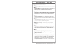
Install and set up the MKP 2000 as follows:
Step 1
Turn all of the equipment off and disconnect it from the power source.
Step 2
Install the cables to and from the control panel in a wall, podium, or
desk. See Rear Panel and Side Panel Connections in chapter 2,
Installation, for guidelines.
Step 3
Prepare the wall, podium, desk, or other surface to mount the MKP.
See Preparing the site, installing the mud ring or wall box in chapter 2,
Installation.
Step 4
Install the control panel in a wall, podium, desk, or other surface.
See Mounting the MKP to the mud ring or wall box in chapter 2, Installation.
Step 5
Connect the input and output cables. See Rear Panel and Side Panel
Connections in chapter 2, Installation, for guidelines.
Step 6
Connect the power supply. See Power supply wiring in chapter 2,
Installation.
Step 7
Connect power cords and turn on the equipment in the following
order: output devices (such as projectors or monitors), the connected
matrix switcher, and input devices (such as DSSs or cable boxes).
Step 8
If necessary, set the control panel’s and matrix switcher’s IP
parameters. See Viewing and configuring the IP and and MKP set-up
parameters in chapter 3, Local Operation, or System Settings Page in
chapter 5, HTML Operation.
Step 9
If necessary, set the control panel’s RS-232 port for pass-through or
no-pass-through mode and whether the MKP is the primary device
(connected to the switcher) or secondary device (connected through
another device). See Viewing and configuring the IP and and MKP
set-up parameters in chapter 3, Local Operation, or System Settings Page
in chapter 5, HTML Operation.
Quick Start Guide — MKP 2000

MKP 2000 Remote Control Panel • Quick Start Guide
Quick Start Guide — MKP 2000, cont’d
iMKP 2000 Remote Control Panel• Table of Contents
Chapter 1 • Introduction ..........................................................1-1
About the MKP 2000 Remote Control Panel ...........1-2
RS-232 connection to the switcher ....................................... 1-3
Ethernet connection to the switcher ...................................1-3
Chapter 2 • Installation.............................................................2-1
MKP Installation Overview...............................................2-2
UL Requirements for Wall Box Installation .............2-3
Installation Procedures.......................................................2-3
Preparing the site, installing the mud ring or wall box...... 2-4
Mounting the MKP to the mud ring or wall box ................2-7
Rear Panel and Side Panel Connections ....................2-8
Control connections ............................................................2-10
RS-232 cable termination.................................................2-11
TP cable termination ........................................................... 2-12
Power supply wiring............................................................ 2-14
Chapter 3 • Local Operation ..................................................3-1
Front Panel Controls and Indications .........................3-2
Front Panel Operations....................................................... 3-3
Creating a tie ......................................................................... 3-3
Viewing the last input or output tied from the MKP .........3-4
Viewing and configuring the IP and MKP
set-up parameters..................................................................3-4
Host control port setting and
pass-through communications
...........................................3-7
Control panel security lockout (executive mode)................3-8
Rear Panel Resets ..................................................................3-8
Performing soft resets ...........................................................3-8
Performing a hard reset ...................................................... 3-10
Chapter 4 • SIS Operation .......................................................4-1
RS-232 Links.............................................................................. 4-2
Routing matrix switcher commands.....................................4-2
Ethernet Link ...........................................................................4-3
Default IP address.................................................................. 4-3
Host-to-MKP Instructions ..................................................4-3
MKP-Initiated (Unsolicited) Messages........................4-3
MKP Error Responses...........................................................4-4
Using the Command/Response Table ..........................4-4
Table of Contents
QS-2
Step 10
Program the control panel with the size of the connected switcher.
See System Settings Page in chapter 5, HTML Operation.
Step 11
Use the control panel to select inputs and outputs. See Front Panel
Operations in chapter 3, Local Operation.

ii
MKP 2000 Remote Control Panel • Table of Contents
Table of Contents, cont’d
MKP 2000 Remote Control Panel
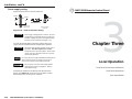
1
Chapter One
Introduction
About the MKP 2000 Remote Control Panel
68-971-01 A
01 05
All trademarks mentioned in this manual are the properties of their respective owners.
Symbol definitions for MKP SIS commands ......................... 4-6
Command/response table for MKP SIS commands..............4-8
Chapter 5 • HTML Operation..................................................5-1
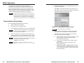
Dowload the Startup Page ...............................................5-2
System Status Page .............................................................. 5-4
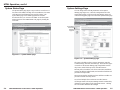
System Settings Page.......................................................... 5-5
IP Settings section.................................................................. 5-6
Unit Name field ................................................................. 5-6
DHCP radio buttons ........................................................... 5-6
IP Address field .................................................................. 5-6
Gateway IP Address field ...................................................5-6
Subnet Mask field..............................................................5-6
MAC Address field .............................................................5-6
Switcher Settings section ...................................................... 5-7
MKP Connection Priority settings ......................................5-7
Host Control Port settings ................................................. 5-7
Switcher IP settings............................................................5-7
Switcher Size settings ........................................................ 5-7
Authorized inputs and authorized outputs .......................5-8
Front panel configuration lock.......................................... 5-8
Date/Time Settings fields.......................................................5-8
Port (RS-232) Settings Page .............................................5-9
Passwords Page .................................................................... 5-10
Firmware Upgrade Page ..................................................5-11
File Management Page .....................................................5-13
Special Characters............................................................... 5-14
Appendix A • Reference Data.............................................. A-1
Specifications ......................................................................... A-2
Part Numbers.......................................................................... A-3
Included parts ....................................................................... A-3
Installation accessories ......................................................... A-3
Cables .................................................................................... A-3
Mounting and Cabling Specifications ....................... A-4
Electrical box cutout............................................................. A-4
Panel mount cutout template ............................................. A-4
Extron Comm-Link cable ...................................................... A-6

MKP 2000 Remote Control Panel • Introduction
MKP 2000 Remote Control Panel • Introduction
Introduction
This manual provides installation and operation instructions for
the Extron MKP 2000.
About the MKP 2000 Remote Control Panel
The MKP 2000 is a network-ready remote control panel that can
control any Extron matrix switcher. The MKP’s RS-232 ports
allow it to communicate with other devices (another MKP or a
matrix switcher) locally and its Ethernet port allows it to
communicate with multiple devices.
An MKP 2000 user can remotely create ties by specifying an
input and then an output to be tied to the input. The MKP can
also be dedicated to a specific group of inputs and outputs
when configured using the built-in Web pages.
The MKP 2000 is mounted in a two-gang wall plate that can be
installed in a wall, conference table, podium, or other
convenient location.
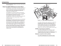
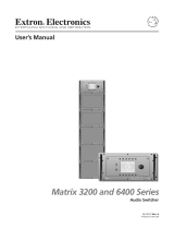
Although the matrix switcher system can have up to 128 inputs
and 128 outputs, a conference room may have 3 input devices
and 2 output devices, a training room next door may have 4
input devices and 1 output device, and so on. Typically, each
room will have one or more MKP control panels assigned to it,
with each MKP limited to the inputs and outputs that it can
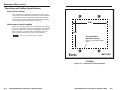
control. In the example in Figure 1-1, the “presentation room”
(top center) has one output device, projector (C) and four input
devices: a video camera (13), a laptop computer (12) and two
PCs (11 and 14). The “Media Room” contains the matrix
switcher, as well as other inputs (1-6) and possibility some
control device(s).
1-2 1-3
Presentation
Room
Video Conference
Room
Training
Room
Media
Room
E
x
t
r
on
E
le
c
tr
o
n
i
c
s
MKP-2000
Keypad
C
O
M
P
A
Q
P
C
C
O
M
P
A
Q
P
C
C
O
M
P
A
Q
P
C
P
la
y
e
r
2
D
V
D
P
la
y
e
r
3
V
C
R
P
l
a
y
e
r
1
V
C
R
L
a
s
e
r
D
e
v
i
c
e
C
o
n
t
r
o
ll
e
r
D
S
S
HO
RIZ
O
N
TAL S
ync
V
ER
TICA
L Sync
AU
D
IO
GR
EE
N
B
LU
E
RED
A
C
Input
1-6
Input
7-9
Input
10
D
B
Input
11
Input
13
Input
14
12
MKP 2000
456
123
789
BACK 0
CANCEL
INPUT OUTPUT
TAKE
Figure 1-1 — Typical MKP 2000 applications
An overflow crowd in the video conference room and/or the
training room may need to see a lecture going on in the
presentation room. In this case, the video camera (input 13)
must be available to those other rooms, so the MKPs in the
video conference and training rooms will be programmed to
allow selection of input 13 for displays in those rooms, in
addition to any video sources and/or displays in those rooms.
RS-232 connection to the switcher
Any number of MKP 2000s can be connected to a matrix
switcher through its RS-232 port, but one MKP must be
designated as the primary controller. Other MKPs can be daisy
chained through the primary MKP remote control panel.
Ethernet connection to the switcher
Any number of MKP 2000s can be connected to a matrix
switcher as part of an Ethernet local area network (LAN).

MKP 2000 Remote Control Panel • Introduction
MKP 2000 Remote Control Panel • Introduction
Introduction
2
Chapter Two
Installation
MKP Installation Overview
UL Requirements for Wall Box Installation
Installation Procedures
Rear Panel and Side Panel Connections
1-4

MKP 2000 Remote Control Panel • Installation
MKP 2000 Remote Control Panel • Installation
Installation
2-3
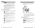
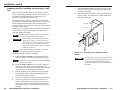
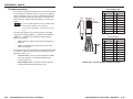
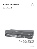
UL Requirements for Wall Box Installation
The following Underwriters Laboratories (UL) requirements
pertain to the installation of the MKP 2000 into a wall or
furniture (figure 2-1).
MKP
200
0
4
5
6
1
23
7
8
9
B
A
C
K
0
CANC
EL
INPUT
OUTPUT
TAKE
R
Figure 2-1 — MKP mounted in a wall box
1. These units are not to be connected to a centralized DC
power source or used beyond their rated voltage range.
2. These units must be installed in UL listed junction boxes.
3. These units must be installed with conduit in accordance
with the National Electrical Code.
Installation Procedures
The MKPs are mounted into a wall, furniture, or any other
convenient location. Follow the instructions appropriate to the
mounting option you have selected.
CAUTION
The control panel must be installed into an
Underwriters Laboratories (UL) approved electrical
wall box.
When installing MKP control panels, you must conform
to all national and local electrical codes.
CAUTION
Installation and service must be performed by
authorized personnel only. UL Listed electrical
boxes are recommended. See UL Requirements
for Wall Box Installation on the next page.
The MKP 2000 remote control panel should be installed in a
standard, 2-gang electrical wall box (figure 2-1). Figure 2-1 shows
the MKP installed in a wall. This could also be in a desk, a
podium, or any other convenient location.
The procedures provided here assume that the electrical wall
boxes and the cables have been installed for the system. Rear
Panel and Side Panel Connections, starting on page 2-8 provides
guidance for terminating the cables.
MKP Installation Overview
To install an MKP 2000 remote control panel, follow these steps:
1
Disconnect power from the matrix switcher and all MKPs
in the system.
2
Prepare the site: cut a hole in the wall/furniture, install
the electrical box or mud ring, and prepare the cables.
Instructions are included in this manual and/or with the
wall box. See Preparing the site, installing the mud ring or
wall box in this chapter.
3
Connect the cable between the MKP and the
matrix switcher. See Rear Panel and Side Panel Connections
on page 2-8.
4
Connect power cords to the MKP and the matrix switcher.
5
Test the MKP’s ability to communicate with the matrix
switcher.
6
Disconnect power from all the devices.
7
Mount the MKP into the electrical box or to the mud ring.
If using a wall box, see Mounting the control panel to the
mud ring or wall box in this chapter.
8
Restore power to the devices.
2-2

MKP 2000 Remote Control Panel • Installation
MKP 2000 Remote Control Panel • Installation
Installation, cont’d
Preparing the site, installing the mud ring or wall
box
Choose a location that allows cable runs without interference.
Allow enough depth for both the wall box and the cables. You
may need to install the cables into the wall, furniture, or
conduits before installing the control panel.
The installation must conform to national and local electrical
codes and to the equipment’s size requirements. An actual-size
cut-out template that shows the cutout requirement for the
circuitry enclosure on the rear of the control panel is provided in
appendix A of this manual.
Installation using a UL listed wall box (available from Extron) is
recommended for most mounting options, but the included
mud rings can be used instead.
Before using the mud rings, verify that the installation
conforms to national and local electrical codes.
CAUTION
Extron provides one mud ring with each MKP
control panel. However, the user may choose to
use a wall box. Because the tolerances on electrical
boxes are very loose, it is recommended that you
measure the actual box that you plan to use before
making any precise cuts.
The electrical box must be at least 2.5" (7 cm) deep to
accommodate the MKP’s rear enclosure.
Install the mud ring or wall box as follows:
1a. If you are using a mud ring, use the template that came
with the mud ring. Cut out the indicated center portion.
To meet the UL listing requirements, this device must be
installed in a wall box.
1b. If you are using a wall box, cut out or make a 100% size
photocopy of the cut-out template in appendix A that
corresponds to the faceplate you are using, and cut out the
center portion of it as indicated on the template.
2. Place the template (or the wall box or mud ring) against
the installation surface, and mark the guidelines for the
opening on the wall or furniture.
3. Cut out the wall/furniture material from the marked area.
4. Check the opening size by inserting the wall box, mud
ring, or control panel into the opening. The box or mud
ring (if used) and/or control panel should fit easily into
the opening. Enlarge or smooth the edges of the opening
if needed.
5. If you are using a wall box, feed cables through the wall
box punch-out holes, and secure them with cable clamps
to provide strain relief.
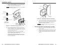
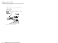
6. Exposed cable shields (braids or foil) are potential sources
of short circuits. Trim back and/or insulate shields with
heat shrink (figure 2-2).
Installation
Cable
Cable
Clamp
Wall Stud
Foil
Shield
Screws or Nails
Screw
Braided
Shield
Figure 2-2 — Grounding outer braided and foil
shields
To prevent short circuits, the outer foil shield can be
cut back to the point where the cable exits the cable
clamp. Both braided and foil shields should be
connected to an equipment ground at the other end
of the cable.
2-52-4

MKP 2000 Remote Control Panel • Installation
MKP 2000 Remote Control Panel • Installation
Installation, cont’d
2-6
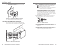
7a. If you are using a mud ring, follow the directions, if any,
that came with the mud ring to attach the clips that fasten
the ring to the wall or furniture (figure 2-3).
To meet the UL listing requirements, this device must be
installed in a wall box.
M
K
P
2
0
0
0
4
5
6
1
2
3
7
89
B
A
C
K
0
C
A
N
C
E
L
I
N
P
U
TO
U
T
P
U
T
T
A
K
E
R
Detail A
0.75" #6-32 Screw
Backing Clip
Backing Clip
Sheet Rock
Sheet Rock
Mounting Bracket
Mounting Bracket
Detail B
1.25" #6-32 Screw
Backing Clip can
be in either orientation.
See Detail A or Detail B.
Extron
MKP 2000
Figure 2-3 — Attaching a mud ring to a wall
7b. If you are using a wall box, insert the wall box into the
opening, and attach it to the wall stud/furniture with nails
or screws, leaving the front edge flush with the outer wall
or furniture surface (figure 2-4).
If attaching the wall box to wood, use four #8 or #10
screws or 10-penny nails. A minimum of 1/2 inch (1.3 cm)
of screw threads must penetrate the wood.
If attaching the wall box to metal studs or furniture, use
four #8 or #10 self-tapping sheet metal screws or machine
bolts with matching nuts.
Flush with
Wall Surface
Screws or Nails
Wall Stud
Wall Box
Figure 2-4 — Attaching a wall box to a wall stud
8. Connect the Ethernet and/or RS-232 cable (as appropriate)
and the power cable and test the MKP before fastening the
MKP into the wall box. See Rear Panel and Side Panel
Connections on page 2-8, for details.
The rear panel connectors will be inaccessible after
installation.
Mounting the MKP to the mud ring or wall box
1. Remove power from the control panel by disconnecting
the power supply.
2. Place the control panel through the opening in the wall or
furniture and into the wall box. Take care not to damage
the cables, which fit behind the MKP, at the back of the
wall box.
2-7

MKP 2000 Remote Control Panel • Installation
MKP 2000 Remote Control Panel • Installation
Installation, cont’d
3. Mount the MKP’s faceplate to the mud ring or wall box
with machine screws (figure 2-5).
M
K
P 200
0
4
5
6
1
23
7
8
9
B
A
C
K
0
CANC
EL
INPUT
OUTPUT
TAKE
R
Figure 2-5 — Mounting the MKP to the wall box
4. Reconnect the power supply and restore power.
Rear Panel and Side Panel Connections
All connectors are on the rear or side of the MKP (figure 2-6).
These connectors will be inaccessible once the MKP is installed.
Tx
HOST
RS-232
SWITCH
RS-232
Rx
GND
Tx
Rx
GND
12 VDC
LAN
PRESS TAB WITH
TWEEKER TO REMOVE
GND
Tx
HOS
T
RS-232
SWI
TCH
RS-232
Rx
GND
Tx
Rx
GND
12 VDC
LAN
PRESS TAB WITH
TWEEKER TO REMOVE
GND
2
1
3
4
Figure 2-6 — MKP rear and side panels
1
LAN (Ethernet) port — If desired, connect a Category (CAT) 5e
or higher (network) cable between this connector and
either the matrix switcher to be controlled or to an
Ethernet local area network (LAN).
See TP cable termination, on page 2-12, to properly wire
the RJ-45 connector for your application.
Ethernet connection indicators — The Link and Act LEDs
indicate the status of the Ethernet connection. The Link LED
indicates that the MKP is properly connected to an Ethernet
LAN. This LED should light steadily. The Act LED indicates
transmission of data packets on the RJ-45 connector. This LED
should flicker as the MKP communicates.
2
Host RS-232 port — If desired, connect a host computer or
control system to this 3-pole, 3.5 mm, RS-232 connector
(figure 2-7).
Pin Function
TX
RX
Gnd
Transmit data
Receive data
Signal ground
Tx
HOST
RS-232
SWITCH
RS-232
Rx
GND
Tx
Rx
GND
Figure 2-7 — RS-232 connector
3
Switcher RS-232 port — If desired, connect a cable between this
3-pole, 3.5 mm, RS-232 connector and a matrix switcher
(figure 2-7).
4
Power connector — Plug the included external 12 VDC power
supply into this 2-pole captive screw connector. See Power
supply wiring, on page 2-14 to wire the connector.
LAN
2-92-8

MKP 2000 Remote Control Panel • Installation
MKP 2000 Remote Control Panel • Installation
Installation, cont’d
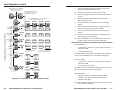
Control connections
The MKP has two RS-232 ports; a Host port (
1
) and a Switcher
port (
2
); and an Ethernet (LAN) port (
3
).
An MKP control panel can be directly connected to any Extron
matrix switcher through the switcher’s RS-232 port (figure 2-8).
A control system or host computer can be connected via the
MKP’s host RS-232 port. Additional MKPs can be connected to
the matrix switcher through the MKP that is RS-232 connected
to the switcher (the primary MKP). The additional (secondary)
MKPs are connected to the primary MKP via the primary
MKP’s Ethernet port.
Ethernet
MKP 2000
MKP 2000
MKP 2000
MKP 2000
MKP 2000
Host
RS-232 Port
Switcher
RS-232 Port
Ethernet
Control
System
Matrix Switcher
MKP 2000
456
123
789
BACK 0
CANCEL
INPUT OUTPUT
TAKE
MKP 2000
456
123
789
BACK 0
CANCEL
INPUT OUTPUT
TAKE
MKP 2000
456
123
789
BACK 0
CANCEL
INPUT OUTPUT
TAKE
MKP 2000
456
123
789
BACK 0
CANCEL
INPUT OUTPUT
TAKE
MKP 2000
456
123
789
BACK 0
CANCEL
INPUT OUTPUT
TAKE
I
N
P
U
T
S
CONTROL
O
U
T
P
U
T
S
I/O
1 2 3 4 5 6 7 8 9 10 11 12
13 14 15 16 17 18 19 20 21 22 23 24
1 2 3 4 5 6 7 8 9 10 11 12
13 14 15 16 17 18 19 20 21 22 23 24
MAV 2400 SERIES SWITCHER
Figure 2-8 — MKP connection using the RS-232 port
An MKP control panel can be directly connected to any
Ethernet-enabled matrix switcher via the switcher’s Ethernet
port (figure 2-9) using a network (TP) cable that is wired as a
crossover cable (see TP cable termination to properly wire the
cable).
MKP 2000
Crossover
Cable
LAN Port
Matrix Switcher
MKP 2000
456
123
789
BACK 0
CANCEL
INPUT OUTPUT
TAKE
I
N
P
U
T
S
CONTROL
O
U
T
P
U
T
S
I/O
1 2 3 4 5 6 7 8 9 10 11 12
13 14 15 16 17 18 19 20 21 22 23 24
1 2 3 4 5 6 7 8 9 10 11 12
13 14 15 16 17 18 19 20 21 22 23 24
MAV 2400 SERIES SWITCHER
Figure 2-9 — Direct MKP connection using the LAN
port
Any number of control panels can be connected, as part of a
network, to any Ethernet-enabled matrix switcher via the
switcher’s Ethernet port (figure 2-10). All TP cables in this
example are wired as patch (straight) cables.
Ethernet
MKP 2000
MKP 2000
MKP 2000
PC
Patch
Cable
Matrix Switcher
MKP 2000
456
123
789
BACK 0
CANCEL
INPUT OUTPUT
TAKE
MKP 2000
456
123
789
BACK 0
CANCEL
INPUT OUTPUT
TAKE
MKP 2000
456
123
789
BACK 0
CANCEL
INPUT OUTPUT
TAKE
I
N
P
U
T
S
CONTROL
O
U
T
P
U
T
S
I/O
1 2 3 4 5 6 7 8 9 10 11 12
13 14 15 16 17 18 19 20 21 22 23 24
1 2 3 4 5 6 7 8 9 10 11 12
13 14 15 16 17 18 19 20 21 22 23 24
MAV 2400 SERIES SWITCHER
Figure 2-10 — Network MKP connection using the
LAN port
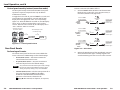
RS-232 cable termination
Each MKP control panel has two RS-232 ports that are
connected using 3.5 mm, 3-pole direct insertion connectors.
Wire the connectors as follows:
The total cable length between an MKP control panel
and a matrix switcher should not exceed 100 feet (30 m).
1. Choose a cable such as Extron’s Comm-Link cable. The
wire specifications for Comm-Link cable are on page A-6.
Colors may vary from this example.
2. Trim approximately 1.5" (3.8 cm) of the cable jacket to
expose the four insulated wires and a bare drain wire
(silver-colored).
3. Cut off the foil shield and discard it.
4. Strip 1/4" ( 0.6 cm) of insulation from three of the four
wires.
5. Twist the strands of each wire, insert them into the direct
insertion connector, and tighten the captive screws.
2-112-10

MKP 2000 Remote Control Panel • Installation
MKP 2000 Remote Control Panel • Installation
Installation, cont’d
TP cable termination
It is vital that your Ethernet cables be the correct cables, and that
they be properly terminated with the correct pinout. Ethernet
links use Category (CAT) 5e or CAT 6, unshielded twisted pair
(UTP) or shielded twisted pair (STP) cables, terminated with
RJ-45 connectors. Ethernet cables are limited to a length 328'
(100 m).
Do not use standard telephone cables. Telephone cables
will not support Ethernet or Fast Ethernet.
Do not stretch or bend cables. Transmission errors can
occur.
The cable used depends on your network speed. The MKP
supports both 10 Mbps (10Base-T — Ethernet) and 100 Mbps
(100Base-T — Fast Ethernet), half-duplex and full-duplex,
Ethernet connections.
• 10Base-T Ethernet requires CAT 3 UTP or STP cable as a
minimum.
• 100Base-T Fast Ethernet requires CAT 5e UTP or STP
cable as a minimum.
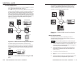
The Ethernet cable can be terminated as a straight-through cable
or a crossover cable and must be properly terminated for your
application (figure 2-11).
• Crossover cable — Direct connection between the MKP
and a host computer or an Ethernet-enabled matrix
switcher (figure 2-9).
• Patch (straight) cable — Network connection between
the MKP and an Ethernet LAN (figure 2-10).
2-132-12
Clip DownSide
1
1&2
3&6
4&5
7&8
2345678
1 Pins2345678
RJ-45
connector
Patch (straight) cable
Twisted
Pairs
Side 1 Side 2
Pin Wire color Pin Wire color
1 White-orange 1 White-orange
2 Orange 2 Orange
3 White-green 3 White-green
4 Blue 4 Blue
5 White-blue 5 White-blue
6 Green 6 Green
7 White-brown 7 White-brown
8 Brown 8 Brown
Crossover cable
Side 1 Side 2
Pin Wire color Pin Wire color
1 White-orange 1 White-green
2 Orange 2 Green
3 White-green 3 White-orange
4 Blue 4 Blue
5 White-blue 5 White-blue
6 Green 6 Orange
7 White-brown 7 White-brown
8 Brown 8 Brown
Figure 2-11 — RJ-45 connector and pinout tables

MKP 2000 Remote Control Panel • Installation
Installation, cont’d
MKP 2000 Remote Control Panel
3
Chapter Three
Local Operation
Front Panel Controls and Indications
Front Panel Operations
Rear Panel Resets
2-14
Power supply wiring
Figure 2-12 shows how to wire the connector.
Power Supply
Output Cord
Direct Insertion
Connector
0.2” (5 mm)
SECTION A–A
Ridges
Smooth
AA
12 V
GND
Figure 2-12 — Power connector wiring
CAUTION
Power supply voltage polarity is critical. Incorrect
voltage polarity can damage the power supply and
the MKP. Identify the power cord negative lead by
the ridges on the side of the cord (figure 2-12).
To verify the polarity before connection, plug in the power
supply with no load and check the output with a voltmeter.
CAUTION
The length of the exposed (stripped) copper wires is
important. The ideal length is 0.2" (5 mm).
Longer bare wires can short together. Shorter wires
are not as secure in the direct insertion connectors
and could be pulled out.
Do not tin the power supply leads before installing in the
direct insertion connector. Tinned wires are not as
secure in the connectors and could be pulled out.
The two power cord wires must be kept separate
while the power supply is plugged in. Remove
power before wiring.
Alternatively, an Extron P/S 100 Universal 12 VDC Power
Supply, part #60-357-01, can power up to ten Extron 12 VDC
devices using only one AC power connector.

MKP 2000 Remote Control Panel • Local Operation
MKP 2000 Remote Control Panel • Local Operation
Local Operation
3-2
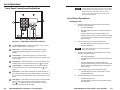
Front Panel Controls and Indications
MKP 2000
456
123
789
BACK 0
CANCEL
INPUT OUTPUT
TAKE
2 63 54
1
7
BACK 0
CANCEL
Figure 3-1 — MKP 2000 controls and indicators
1
0, 1 through 9 buttons — These buttons allow you to enter an
input or output when you create a tie.
2
Back button — This button allows you to delete the least-
significant (rightmost) digit of an entered input or output
number.
3
Cancel button — This button allows you to clear the LED
display to 000, erasing any number that you have entered or any
error message.
4
Input button — This button allows you to specify that the next
number that you enter with the numeric keys (
1
) is an input.
5
Output button — This button allows you to specify that the
next number that you enter with the numeric keys (
1
) is an
output.
6
Take button — This button confirms the potential tie that you
have created with the input and output selection. This button is
the equivalent of the Enter button on the matrix switcher’s front
panel.
7
LED display — This display shows the input or output number
that was most-recently entered using the MKP’s numeric
keys (
1
). In certain modes, it can also show the various IP
addresses programmed into the MKP.
The LED display shows the most recent input or output
number entered on the numeric keys only. Ties created
using other devices (other MKPs, a PC or control
system, or the matrix switcher’s front panel) are not
shown in the LED display.
Front Panel Operations
Creating a tie
1. Press the Input button to specify that the next number
entered is an input number.
• The Input LED lights.
• The LED display shows the last input selected from
this MKP.
• The last selected output is locked (unable to be
changed; assigned as the output to which the entered
input is tied unless a different output is assigned [see
steps 3 and 4]).
2. Use the numeric keys to enter the desired input.
• The LED display shows the input that you enter.
• The Take LED blinks.
If you push the Take button now, the selected input is
tied to the locked output.
3. Press the Output button to specify that the next number
entered is an output number.
• The Output LED lights.
• The LED display shows the last output selected from
this MKP.
• The last selected input is locked (unable to be
changed; assigned as the output to which the entered
input is tied unless a different input is assigned [see
steps 1 and 2]).
4. Use the numeric keys to enter the desired output.
• The LED display shows the output that you enter.
• The Take LED blinks.
5. Press the Take button to confirm the change.
• The Take LED goes out.
• The LED display show the last output that was tied
from this MKP.
3-3

MKP 2000 Remote Control Panel • Local Operation
MKP 2000 Remote Control Panel • Local Operation
Local Operation, cont’d
When an input or output outside the available range for
this MKP or the connected matrix switcher is selected,
the LED display shows N-A.
Viewing the last input or output tied from the MKP
Press either the Input button or the Output button.
• The Input or Output LED lights.
• The LED display shows the last tied input or output
(depending on which LED, Input or Output, is lit).
The LED display shows the most recent input or output
number entered on the numeric keys only. Ties created
using other devices (other MKPs, a PC or control
system, or the matrix switcher’s front panel) are not
shown in the LED display.
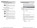
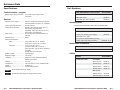
Viewing and configuring the IP and MKP set-up
parameters
To configure the MKP to operate in your LAN system, one or
more of the following IP addresses and the host control port
setting may need to be changed:
• The MKP’s IP address (default = 192.168.254.253)
• The MKP’s subnet address (default = 255.255.0.0)
• The MKP’s gateway address (default = 0.0.0.0)
• The target matrix switcher’s IP address (default = 0.0.0.0)
• Host control port setting (pass-through or no pass-
through) (default = no pass-through)
• MKP’s connection setting
Primary — Controls the switcher directly.
Secondary — Controls the switcher through another
MKP and its Switcher RS-232 port.
Valid IP addresses consist of four 1-, 2-, or 3-digit numeric
subfields (octets) separated by dots (periods). Each octet can be
numbered from 000 through 255. Leading zeroes, up to 3 digits
total per octet, are optional. Values of 256 and above are invalid.
If any of the default address conflict with other equipment at
your installation, you can change the IP address(es) to any valid
value.
Editing the Extron IP address and other parameters
while connected via the LAN port can immediately
disconnect the user from the MKP. Extron recommends
editing this field using the front panel or the RS-232 link
and protecting the Ethernet access to these parameters by
assigning an administrator’s password to qualified and
knowledgeable personnel only.
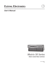
Edit these addresses and set the host control setting as follows:
1. Simultaneously press and hold the Input, Output, and
Take buttons for approximately 2 seconds until the LED
display changes and then release the buttons.
• The LED display shows the most-significant
(left-most) octet of the MKP’s IP address (figure 3-2
on page 3-6).
• Pressing the Input button changes the IP address
shown in the LED display, cycling through the
various IP addresses, and then selects the host
control setting, as shown in figure 3-2.
The Input LED is lit and the Output LED is
unlit when the MKP’s IP address is displayed.
The Input LED is unlit and the Output LED is
lit when the MKP’s subnet mask is displayed.
The Input LED is blinking and the Output LED
is unlit when the MKP’s gateway IP address is
displayed.
The Input LED is unlit and the Output LED is
blinking when the MKP’s target matrix
switcher’s IP address is displayed.
Both the Input LED and the Output LED are lit
when the host control setting is displayed.
Both the Input LED and the Output LED are
blinking when the connection priority is
displayed.
• Pressing the Output button changes the octet of the
selected IP address that is shown in the LED display,
cycling through the four octets as shown in figure 3-2.
No dot (period) appears in the LED display
when the most-significant octet is shown.
A dot (period) appears to the right of the left-
most digit in the LED display when the second
octet is shown.
A dot (period) appears to the right of the second
digit in the LED display when the third octet is
shown.
A dot (period) appears to the right of the right-
most digit in the LED display when the least-
significant octet is shown.
3-53-4

MKP 2000 Remote Control Panel • Local Operation
MKP 2000 Remote Control Panel • Local Operation
Local Operation, cont’d
1 9 21 6 8.2 5 42 5 3..
2
5 52 5 5.0 0 00 0 0..
0 0 00 0 0.0 0 00 0 0..
0
0 00 0 0.
.
.
.
.
.
.
.
.
.
.
.
.0
0 00 0 0..
SECPri
INPUT OUTPUT
TAKE
OUTPUT
OUTPUT
OUTPUT
OUTPUT
OUTPUT
OUTPUT
INPUT
INPUT
INPUT
INPUT
INPUT
OUTPUT
OUTPUT OUTPUT
OUTPUT OUTPUT OUTPUT
INPUT
Simultaneously press and hold
the buttons for 2 seconds.
Release the buttons.
The LED display shows the
most-significant octet of the
MKP 2000’s IP address.
Press the Output button to cycle through
the displayed and editable octets.
Press the Input button to cycle through the displayed and
editable addresses and to reach the MKP set-up settings.
Most-significant Octet
(no dot)
Connected to
Switcher
Control Though
Primary (RS-232)
Least-significant Octet
(dot in right-most position)
OP
n
PA S
OUTPUT OUTPUT
No
Pass-through
Port
Pass-through
MKP 2000’s
IP Address
MKP 2000’s
Subnet Mask
MKP 2000’s
Gateway
Address
Matrix
Switcher’s
IP Address
Connection
Priority
Host Control
Setting
Figure 3-2 — Selecting octet fields and host control
3-6 3-7
2. Use the Input button and Output button to select and
display the desired address and octet.
3. Press the Cancel button to clear the octet to 000.
4. Use the 0 through 9 buttons to enter the desired value for
the octet.
5. Repeat steps 2 through 4 to select and change other
addresses and/or octets.
6. Use the Input button to select the host control setting
display.
7. If necessary, use the Output button to toggle the setting
between pass-through and no pass-through.
8. Use the Input button to select the connection priority
display.
9. If necessary, use the Output button to toggle the setting
between primary and secondary.
10. When all addresses and octets and the host control and
priority settings are correct, press the Take button.
Host control port setting and pass-through communications
When the MKP is:
• Connected to a computer or control system via its Host
RS-232 port and
• Is in pass-through mode,
The MKP redirects valid matrix switcher SIS commands that it
receives on its Host RS-232 port to its Switcher RS-232 port.
When the MKP is:
• Connected to a computer or control system via its Host
RS-232 port and
• Is in no pass-through mode,
The MKP acts on all valid MKP commands received. It does not
pass the command to its Switcher RS-232 port.
When the MKP is:
• Selected as primary, it directly controls the matrix
switcher via its Switch RS-232 port or LAN port
• Selected as secondary,
The MKP controls the matrix switcher through connection to the
primary MKP’s IP address

MKP 2000 Remote Control Panel • Local Operation
MKP 2000 Remote Control Panel • Local Operation
Local Operation, cont’d
3-8
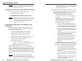
Control panel security lockout (executive mode)
The front panel security lockout limits the MKP’s front panel
operation to input and output selection only (IP address
modification is locked).
To toggle the lock on and off, press and hold the 1, 3, Back, and
Cancel buttons for approximately 3 seconds until the LED
display shows the appropriate “LOC” (on or off) message
(figure 3-3). When the MKP lock is turned on, the LED display
shows “LOC” for three seconds and then “ON” for three
seconds. When the lock is turned off, the LED display shows
“LOC” and then “OFF” for 3 seconds.
1 3
BACK CANCEL
LOC ON
Simultaneously press
and hold the buttons.
The LED display shows
the LOC message.
3
seconds
3
seconds
Figure 3-3 — Control panel lockout
Rear Panel Resets
Performing soft resets
The remote control panel has three soft resets available that
restore various tiers of MKP settings to their default settings.
• Events (mode 3) reset — This function restarts the
communications and control events.
• IP system (mode 4) reset — IP system reset function
resets most IP protocols to their default settings.
IP system reset clears the Internet protocol (IP) settings,
but does not reset the target address, the host control
setting, the priority setting, or any user-loaded files.
• Absolute (mode 5) reset — Absolute reset performs all of
the system reset functions and clears the MKP’s
IP address to 192.168.254.253 and subnet mask to
255.255.0.0. This function is identical to the
Esc
ZQQQ SIS command, see chapter 4, SIS Operation).
Perform a soft reset of the MKP as follows:
1. Press and hold the Reset (R) button until the Reset LED
blinks off once (events reset), twice (IP system reset), or
three times (absolute reset) (figure 3-4).
R
R
R
R
R
R
R
R
R
6
seconds
LED flashes
twice.
3
seconds
LED flashes
once.
Press and hold
the Reset button.
Release, then
immediately
press and
release again.
Release, then
immediately
press and
release again.
Release, then
immediately
press and
release again.
Absolute
(mode 5)
Reset
Press and hold
the Reset button.
IP System
(Mode 4)
Reset
Press and hold
the Reset button.
Events
(Mode 3)
Reset
9
seconds
LED flashes
three times.
Figure 3-4 — Soft resets
2. Release the Reset button and then immediately press and
release the Reset button again. Nothing happens if the
second momentary press does not occur within 1 second.
3-9

MKP 2000 Remote Control Panel • Local Operation
Local Operation, cont’d
MKP 2000 Remote Control Panel
4
Chapter Four
SIS Operation
RS-232 Links
Ethernet Link
Host-to-MKP Instructions
MKP-Initiated (Unsolicited) Messages
MKP Error Responses
Using the Command/Response Table
3-10
Performing a hard reset
The hard reset function restores the MKP to the original factory
default settings, including the default (factory) firmware
configuration and the default IP settings. A hard reset performs
all of the reset-whole-MKP functions, absolute reset functions,
and erases all user-installed software or firmware. Perform a
hard reset as follows:
Ensure that you have backed up any locally-created
HTML, JavaScript, or other files that you have uploaded
to the MKP’s user file space before you perform the hard
reset. A hard reset will erase all locally-created files
from the MKP.
1. If necessary, turn off power to the switcher.
2. Press and hold the Reset button on the rear panel while
you apply AC power to the MKP (figure 3-5).
Power
R
R
Press and hold the
Reset button while you
apply power to the MKP.
The LED flashes
on and off.
Release the Reset button.
Figure 3-5 — Hard reset

MKP 2000 Remote Control Panel • SIS Operation
MKP 2000 Remote Control Panel • SIS Operation
SIS Operation
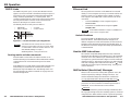
RS-232 Links
The MKP’s rear panel 3-pole, 3.5 mm, Host RS-232 connector
(figure 4-1) can be connected to the RS-232 serial port output of
a host device such as a computer running the HyperTerminal
utility, an RS-232 capable PDA, or a control system. This
connection makes software control of the control panel possible.
The rear panel Switcher connector can be connected to the
Remote or RS-232 port of a matrix switcher.
The default protocol for both ports is as follows:
• 9600 baud* • no parity
• 8-bit, 1 stop bit • no flow control
Pin Function
TX
RX
Gnd
Transmit data
Receive data
Signal ground
Tx
HOST
RS-232
SWITCH
RS-232
Rx
GND
Tx
Rx
GND
Figure 4-1 — RS-232 connector pin assignments
*The default baud rate is 9600, but this can also be
changed, using the MKP’s web pages, to 19200, 38400,
or 115200 baud to match the switcher’s baud rate. See
Port (RS-232) Settings in chapter 5,
HTML Operation, to change the baud rate.
Routing matrix switcher commands
When the MKP is connected to the matrix switcher via its
Switcher RS-232 port, the MKP can redirect SIS matrix switcher
commands received on the Host RS-232 port to the matrix
switcher.
If the MKP receives a valid matrix switcher SIS command on its
Host RS-232 port, it redirects the command to its Switcher
RS-232 port only if the MKP is set to Pass-through mode. See
the pass-through port redirect command set on page 4-8 to set
the Pass-through mode.
Ethernet Link
The rear panel LAN connector on the MKP can be connected
directly to a host computer (for set-up) or a matrix switcher (for
switcher control) or to an Ethernet LAN or WAN (to which a
host computer, other MKPs and a matrix switcher can also be
connected).
• Connection directly to a host computer requires a
crossover cable.
• Connection via an Ethernet LAN requires a patch
(straight) cable.
See TP cable termination in chapter 2, Installation to
create crossover and patch cables.
Default IP address
To access the MKP via the Ethernet port, you will need the
Extron IP address. If the address has been changed to an
address comprised of words and characters, the actual numeric
IP address can be determined using the ping (ICMP) utility. If
the address has not been changed, the factory-specified default
is 192.168.254.253.
Host-to-MKP Instructions
The switcher accepts SIS (Simple Instruction Set) commands
through the Host RS-232 port and Ethernet port. SIS commands
consist of one or more characters per command field. They do
not require any special characters to begin or end the command
character sequence. Each switcher response to an SIS command
ends with a carriage return and a line feed (CR/LF = ), which
signals the end of the response character string. A string is one
or more characters.
MKP-Initiated (Unsolicited) Messages
When a local event such as a front panel operation occurs, the
switcher responds by sending a message to the host. The
switcher-initiated messages are listed below (underlined).
(C) Copyright 2004, Extron Electronics MKP 2000, Vx.xx
The switcher initiates the copyright message when it is first
powered on or when connection via Internet protocol (IP) is
established. Vx.xx is the firmware version number.
Password:
The switcher initiates the password message immediately after
the copyright message when the controlling system is connected
using TCP/IP or Telnet and the switcher is password protected.
4-34-2
Page is loading ...
Page is loading ...
Page is loading ...
Page is loading ...
Page is loading ...
Page is loading ...
Page is loading ...
Page is loading ...
Page is loading ...
Page is loading ...
Page is loading ...
Page is loading ...
Page is loading ...
Page is loading ...
Page is loading ...
-
 1
1
-
 2
2
-
 3
3
-
 4
4
-
 5
5
-
 6
6
-
 7
7
-
 8
8
-
 9
9
-
 10
10
-
 11
11
-
 12
12
-
 13
13
-
 14
14
-
 15
15
-
 16
16
-
 17
17
-
 18
18
-
 19
19
-
 20
20
-
 21
21
-
 22
22
-
 23
23
-
 24
24
-
 25
25
-
 26
26
-
 27
27
-
 28
28
-
 29
29
-
 30
30
-
 31
31
-
 32
32
-
 33
33
-
 34
34
-
 35
35


Extron electronics Universal Remote MKP 2000 User manual
- Type
- User manual
- This manual is also suitable for
Ask a question and I''ll find the answer in the document
Finding information in a document is now easier with AI
Related papers
-
 Extron electronics MKP 2000 User manual
-
 Extron electronics MCP 1000 User manual
-
 Extron electronics Matrix 3200 Series User manual
-
Extron 12800 User manual
-
Extron 3200 Series User manual
-
 Extron electronics 3200 User manual
-
Extron electronics MVX VGA A User manual
-
 Extron electronics 42 HVA User manual
-
 Extron electronics Extron Electronics Switch 50 User manual
-


Other documents
-
-
-
-
-
Extron electronic MKP 1000 User manual
-
Extron MTPX 816 User manual
-
-
-
-