User Guide
MKP 2000
Matrix Switchers
Remote Control Panel
68-971-01 Rev.
E
01 19

Safety Instructions
Safety Instructions • English
WARNING: This symbol, ,when used on the product, is
intended to alert the user of the presence of uninsulated dangerous
voltage within the product’s enclosure that may present a risk of electric
shock.
ATTENTION: This symbol, , when used on the product, is intended
to alert the user of important operating and maintenance (servicing)
instructions in the literature provided with the equipment.
For information on safety guidelines, regulatory compliances, EMI/EMF
compatibility, accessibility, and related topics, see the Extron Safety and
Regulatory Compliance Guide, part number 68-290-01, on the Extron
website, www.extron.com.
Sicherheitsanweisungen • Deutsch
WARNUNG: Dieses Symbol auf dem Produkt soll den Benutzer
darauf aufmerksam machen, dass im Inneren des Gehäuses dieses
Produktes gefährliche Spannungen herrschen, die nicht isoliert sind und
die einen elektrischen Schlag verursachen können.
VORSICHT: Dieses Symbol auf dem Produkt soll dem Benutzer in
der im Lieferumfang enthaltenen Dokumentation besonders wichtige
Hinweise zur Bedienung und Wartung (Instandhaltung) geben.
Weitere Informationen über die Sicherheitsrichtlinien, Produkthandhabung,
EMI/EMF-Kompatibilität, Zugänglichkeit und verwandte Themen finden Sie in
den Extron-Richtlinien für Sicherheit und Handhabung (Artikelnummer
68-290-01) auf der Extron-Website, www.extron.com.
Instrucciones de seguridad • Español
ADVERTENCIA: Este símbolo, , cuando se utiliza en el producto,
avisa al usuario de la presencia de voltaje peligroso sin aislar dentro del
producto, lo que puede representar un riesgo de descarga eléctrica.
ATENCIÓN: Este símbolo, , cuando se utiliza en el producto, avisa
al usuario de la presencia de importantes instrucciones de uso y
mantenimiento recogidas en la documentación proporcionada con el
equipo.
Para obtener información sobre directrices de seguridad, cumplimiento
de normativas, compatibilidad electromagnética, accesibilidad y temas
relacionados, consulte la Guía de cumplimiento de normativas y seguridad
de Extron, referencia 68-290-01, en el sitio Web de Extron, www.extron.com.
Instructions de sécurité • Français
AVERTISSEMENT : Ce pictogramme, , lorsqu’il est utilisé sur le
produit, signale à l’utilisateur la présence à l’intérieur du boîtier du
produit d’une tension électrique dangereuse susceptible de provoquer
un choc électrique.
ATTENTION : Ce pictogramme, , lorsqu’il est utilisé sur le produit,
signale à l’utilisateur des instructions d’utilisation ou de maintenance
importantes qui se trouvent dans la documentation fournie avec le
matériel.
Pour en savoir plus sur les règles de sécurité, la conformité à la
réglementation, la compatibilité EMI/EMF, l’accessibilité, et autres sujets
connexes, lisez les informations de sécurité et de conformité Extron, réf.
68-290-01, sur le site Extron, www.extron.com.
Istruzioni di sicurezza • Italiano
AVVERTENZA: Il simbolo, , se usato sul prodotto, serve ad
avvertire l’utente della presenza di tensione non isolata pericolosa
all’interno del contenitore del prodotto che può costituire un rischio di
scosse elettriche.
ATTENTZIONE: Il simbolo, , se usato sul prodotto, serve ad
avvertire l’utente della presenza di importanti istruzioni di funzionamento
e manutenzione nella documentazione fornita con l’apparecchio.
Per informazioni su parametri di sicurezza, conformità alle normative,
compatibilità EMI/EMF, accessibilità e argomenti simili, fare riferimento
alla Guida alla conformità normativa e di sicurezza di Extron, cod. articolo
68-290-01, sul sito web di Extron, www.extron.com.
Instrukcje bezpieczeństwa • Polska
OSTRZEŻENIE: Ten symbol, , gdy używany na produkt, ma na celu
poinformować użytkownika o obecności izolowanego i niebezpiecznego
napięcia wewnątrz obudowy produktu, który może stanowić zagrożenie
porażenia prądem elektrycznym.
UWAGI: Ten symbol, , gdy używany na produkt, jest przeznaczony do
ostrzegania użytkownika ważne operacyjne oraz instrukcje konserwacji
(obsługi) w literaturze, wyposażone w sprzęt.
Informacji na temat wytycznych w sprawie bezpieczeństwa, regulacji
wzajemnej zgodności, zgodność EMI/EMF, dostępności i Tematy pokrewne,
zobacz Extron bezpieczeństwa i regulacyjnego zgodności przewodnik, część
numer 68-290-01, na stronie internetowej Extron, www.extron.com.
Инструкция по технике безопасности • Русский
ПРЕДУПРЕЖДЕНИЕ: Данный символ, , если указан
на продукте, предупреждает пользователя о наличии
неизолированного опасного напряжения внутри корпуса
продукта, которое может привести к поражению
электрическим током.
ВНИМАНИЕ: Данный символ, , если указан на продукте,
предупреждает пользователя о наличии важных инструкций
по эксплуатации и обслуживанию в руководстве,
прилагаемом к данному оборудованию.
Для получения информации о правилах техники безопасности,
соблюдении нормативных требований, электромагнитной
совместимости (ЭМП/ЭДС), возможности доступа и других
вопросах см. руководство по безопасности и соблюдению
нормативных требований Extron на сайте Extron: ,
www.extron.com, номер по каталогу - 68-290-01.
安全说明 • 简体中文
警告: 产品上的这个标志意在警告用户该产品机壳内有暴露的危险 电压,
有触电危险。
注意: 产品上的这个标志意在提示用户设备随附的用户手册中有
重要的操作和维护(维修)说明。
关于我们产品的安全指南、遵循的规范、EMI/EMF 的兼容性、无障碍
使用的特性等相关内容,敬请访问 Extron 网站 , www.extron.com,参见
Extron 安全规范指南,产品编号 68-290-01
。

안전 지침 • 한국어
경고: 이 기호 가 제품에 사용될 경우, 제품의 인클로저 내에 있는
접지되지 않은 위험한 전류로 인해 사용자가 감전될 위험이 있음을
경고합니다.
주의: 이 기호 가 제품에 사용될 경우, 장비와 함께 제공된 책자에 나와
있는 주요 운영 및 유지보수(정비) 지침을 경고합니다.
안전 가이드라인, 규제 준수, EMI/EMF 호환성, 접근성, 그리고 관련 항목에
대한 자세한 내용은 Extron 웹 사이트(www.extron.com)의 Extron 안전 및
규제 준수 안내서, 68-290-01 조항을 참조하십시오.
安全記事 • 繁體中文
警告: 若產品上使用此符號,是為了提醒使用者,產品機殼內存在著
可能會導致觸電之風險的未絕緣危險電壓。
注意 若產品上使用此符號,是為了提醒使用者,設備隨附的用戶手冊中有
重要的操作和維護(維修)説明。
有關安全性指導方針、法規遵守、EMI/EMF 相容性、存取範圍和相關主題的詳細資
訊,請瀏覽 Extron 網站:www.extron.com,然後參閱《Extron 安全性與法規
遵守手冊》,準則編號 68-290-01。
安全上のご注意 • 日本語
警告: この記号 が製品上に表示されている場合は、筐体内に絶縁されて
いない高電圧が流れ、感電の危険があることを示しています。
注意:この記号 が製品上に表示されている場合は、本機の取扱説明書に
記載されている重要な操作と保守(整備)の指示についてユーザーの注意
を喚起するものです。
安全上のご注意、法規厳守、EMI/EMF適合性、その他の関連項目に
つ い て は 、エ ク スト ロ ン の ウ ェブ サ イト www.extron.com よ り 『 Extron Safety
and Regulatory Compliance Guide』 ( P/N 68-290-01) をご覧ください。
Copyright
© 2007-2019 Extron Electronics. All rights reserved. www.extron.com
Trademarks
All trademarks mentioned in this guide are the properties of their respective owners.
The following registered trademarks (
®
), registered service marks (
SM
), and trademarks (
TM
) are the property of RGBSystems, Inc. or
ExtronElectronics (see the current list of trademarks on the T
erms of Use page at www.extron.com):
Registered Trademarks
(
®
)
Extron, Cable Cubby, ControlScript, CrossPoint, DTP, eBUS, EDID Manager, EDID Minder, Flat Field, FlexOS, Glitch Free. Global
Configurator, GlobalScripter, GlobalViewer, Hideaway, HyperLane, IPIntercom, IPLink, KeyMinder, LinkLicense, LockIt, MediaLink,
MediaPort, NetPA, PlenumVault, PoleVault, PowerCage, PURE3, Quantum, Show Me, SoundField, SpeedMount, SpeedSwitch,
StudioStation, SystemINTEGRATOR, TeamWork, TouchLink, V-Lock, VideoLounge, VN-Matrix, VoiceLift, WallVault, WindoWall, XTP,
XTPSystems, and ZipClip
Registered Service Mark
(SM)
: S3 Service Support Solutions
Trademarks
(
™
)
AAP, AFL (Accu-RateFrameLock), ADSP(Advanced Digital Sync Processing), Auto-Image, CableCover, CDRS(ClassD Ripple
Suppression), Codec Connect, DDSP(Digital Display Sync Processing), DMI (DynamicMotionInterpolation), DriverConfigurator,
DSPConfigurator, DSVP(Digital Sync Validation Processing), eLink, EQIP, Everlast, FastBite, FOX, FOXBOX,
IP Intercom HelpDesk, MAAP, MicroDigital, Opti-Torque, PendantConnect, ProDSP, QS-FPC(QuickSwitch Front Panel Controller),
RoomAgent, Scope-Trigger, ShareLink, SIS, SimpleInstructionSet, Skew-Free, SpeedNav, Triple-Action Switching, True4K, Vector™ 4K ,
WebShare, XTRA, and ZipCaddy

FCC Class A Notice
This equipment has been tested and found to comply with the limits for a Class A digital
device, pursuant to part15 of the FCC rules. The ClassA limits provide reasonable
protection against harmful interference when the equipment is operated in a commercial
environment. This equipment generates, uses, and can radiate radio frequency energy
and, if not installed and used in accordance with the instruction manual, may cause
harmful interference to radio communications. Operation of this equipment in a
residential area is likely to cause interference. This interference must be corrected at the
expense of the user.
NOTE: For more information on safety guidelines, regulatory compliances, EMI/
EMF compatibility, accessibility, and related topics, see the Extron Safety and
Regulatory Compliance Guide on the Extron website.
Battery Notice
This product contains a battery. Do not open the unit to replace the battery. If the
battery needs replacing, return the entire unit to Extron (for the correct address, see the
Extron Warranty section on the last page of this guide).
CAUTION: Risk of explosion. Do not replace the battery with an incorrect type.
Dispose of used batteries according to the instructions.
ATTENTION : Risque d’explosion. Ne pas remplacer la pile par le mauvais type de
pile. Débarrassez-vous des piles usagées selon le mode d’emploi.

Conventions Used in this Guide
Notifications
The following notifications are used in this guide:
CAUTION: Risk of minor personal injury.
ATTENTION : Risque de blessuremineure.
ATTENTION:
• Risk of property damage.
• Risque de dommages matériels.
NOTE: A note draws attention to important information.
Software Commands
Commands are written in the fonts shown here:
^AR Merge Scene,,0p1 scene 1,1 ^B 51 ^W^C.0
[01] R 0004 00300 00400 00800 00600 [02] 35 [17] [03]
E X! *X1&* X2)* X2#* X2! CE}
NOTE: For commands and examples of computer or device responses used in
this guide, the character “0” is used for the number zero and “O” is the capital
letter “o.”
Computer responses and directory paths that do not have variables are written in the
font shown here:
Reply from 208.132.180.48: bytes=32 times=2ms TTL=32
C:\Program Files\Extron
Variables are written in slanted form as shown here:
ping xxx.xxx.xxx.xxx —t
SOH R Data STX Command ETB ETX
Selectable items, such as menu names, menu options, buttons, tabs, and field names
are written in the font shown here:
From the File menu, select New.
Click the OK button.
Specifications Availability
Product specifications are available on the Extron website, www.extron.com.
Extron Glossary of Terms
A glossary of terms is available at http://www.extron.com/technology/glossary.aspx.


Contents
Remote Control ............................................ 23
Connections Options .......................................... 23
RS-232 Links ..................................................23
Ethernet Link ..................................................24
Host-to-device Communtication ......................... 24
MKP-Initiated (Unsolicited) Messages .............24
Error Messages ..............................................25
Using the Command and Response Tables ........25
Symbol Definitions ..........................................26
Timeout .......................................................... 27
Command and Response Table for SIS
Commands .......................................................28
HTML Operation ........................................... 33
Downloading and Startup Page .......................... 33
Viewing System Status ....................................... 34
Using the Configuration Pages ...........................35
System Settings Page ....................................35
IP Settings Section .........................................36
Switcher Control Settings Section ...................37
Date/Time Settings Fields ............................... 38
Port (RS-232) Settings Page ...........................39
Passwords Page.............................................40
Firmware Upgrade Page ................................. 41
Using the File Management Page .......................43
Uploading Files ...............................................44
Adding a Directory .......................................... 44
Other File Management Activities .................... 44
Special Characters .............................................44
Reference Information ................................ 45
Mounting the MKP 2000.....................................45
Electrical Box Cutout ......................................45
Panel Mount Cutout Template .........................45
Introduction .................................................... 1
About this Guide ...................................................1
About the MKP2000 Remote Control Panels ....... 1
Application Diagrams ............................................1
Control Communications ..................................2
Features ...............................................................3
Installation ...................................................... 4
Installation Overview .............................................4
Installation ............................................................5
UL Requirements for Wall Box Installation ......... 5
Installation Procedures ......................................6
Rear Panel and Side Panel Connections ...............9
Control Connections ....................................... 10
RS-232 Cable Termination .............................. 11
TP Cable Termination and
Recommendations ........................................12
Power Supply Wiring ......................................13
Operation ...................................................... 16
Front Panel Controls and Indications ..................16
Front Panel Operations ....................................... 17
Creating a Tie .................................................17
Deselecting a Tie ............................................17
Viewing the last input or output tied
from the MKP ................................................18
Viewing and configuring the IP and
MKP setup parameters ..................................18
Host control port setting and
pass-through communications ......................20
Control Panel Security Lockout
(Executive Mode) ...........................................21
Rear Panel Resets .............................................. 21
Performing Soft Resets ...................................21
Performing a Hard Reset ................................22
viiMKP 2000 • Contents

MKP 2000 • Contentsviii

MKP 2000 • Introduction 1
Introduction
• About this Guide
• About the MKP2000 Remote Control Panels
• Application Diagrams
• Features
About this Guide
This manual provides installation and operation instructions for the Extron MKP2000.
About the MKP2000 Remote Control Panels
The MKP2000 is a network-ready remote control panel that can control any Extron matrix
switcher. The MKP RS-232 ports allow it to communicate with other devices (another MKP
or a matrix switcher) locally and its Ethernet port allows it to communicate with multiple
devices on a LAN network.
An MKP2000 user can remotely create ties by specifying an input and then an output to be
tied to the input. The MKP can also be dedicated to a specific group of inputs and outputs
when configured using the built-in web pages.
The MKP2000 panel is mounted in a two-gang wall plate that can be installed in a wall,
conference table, podium, or other convenient location.
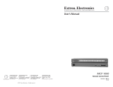
Application Diagrams
The matrix switcher system can have up to 128 inputs and 128 outputs. However, for
example, a conference room may have three input devices and two output devices; a
training room next door may have four input devices and one output device; and so on.
Typically, each room will have one or more MKP control panels assigned to it, with each
MKP limited to the inputs and outputs that it can control.
In the example in figure 1 on the next page, the “presentation room” (top, center) has:
• One output device
• A projector (C)
• Four input devices:
• A video camera (13)
• A laptop computer (12)
• Two PCs (11 and 14)
The “Media Room” (bottom, right) contains the matrix switcher, as well as other inputs (1-6)
and possibly some control devices.

MKP 2000 • Introduction2
Presentation
Room
Video Conference
Room
Training
Room
Media
Room
Extron
Electronics
MKP-2000
Keypad
C
O
M
P
A
Q
PC
C
O
M
PA
Q
PC
C
O
M
PA
Q
PC
Play
er 2
DVD
Play
er 3
VCR
Play
er 1
VCR
Laser
Device
Controller
DSS
HORIZONTAL Sync
VERTICAL Sync
AUDIO
GREEN
BLUE
RED
A
C
Input
1-6
Input
7-9
Input
10
D
B
Input
11
Input
13
Input
14
12
MKP 2000
456
123
789
BACK 0
CANCEL
INPUT OUTPUT
TAKE
Figure 1. Typical MKP 2000 Applications
An overflow crowd in the video conference room and/or the training room may need to see
a lecture going on in the presentation room. In this case, the video camera (input 13) must
be available to those other rooms. Therefore, the MKPs in the video conference and training
rooms will be programmed to allow selection of input 13 for displays in those rooms, in
addition to any video sources and/or displays there.
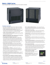
Control Communications
RS-232 connection to the switcher
Any number of MKP 2000s can be connected to a matrix switcher through its RS-232 port,
but one MKP must be designated as the primary control panel. Other MKPs can be daisy-
chained through the primary MKP remote control panel.
Ethernet connection to the switcher
Any number of MKP 2000s can be connected to a matrix switcher as part of an Ethernet
local area network (LAN).
Application diagram
On the next page, figure 2 shows an example of how the MKP 2000 may be connected to
a matrix switcher and other Extron products.
figure 1

MKP 2000 • Introduction 3
Ethernet
MKP 2000
MKP 2000
MKP 2000
MKP 2000
MKP 2000
Host
RS-232 Port
Switcher
RS-232 Port
Ethernet
Control
System
Matrix Switcher
MKP 2000
4 5 6
1 2 3
7 8 9
BACK 0
CANCEL
INPUT OUTPUT
TAKE
MKP 2000
4 5 6
1 2 3
7 8 9
BACK 0
CANCEL
INPUT OUTPUT
TAKE
MKP 2000
4 5 6
1 2 3
7 8 9
BACK 0
CANCEL
INPUT OUTPUT
TAKE
MKP 2000
4 5 6
1 2 3
7 8 9
BACK 0
CANCEL
INPUT OUTPUT
TAKE
MKP 2000
4 5 6
1 2 3
7 8 9
BACK 0
CANCEL
INPUT OUTPUT
TAKE
I
N
P
U
T
S
CONTROL
O
U
T
P
U
T
S
I/O
1 2 3 4 5 6 7 8 9 10 11 12
13 14 15 16 17 18 19 20 21 22 23 24
1 2 3 4 5 6 7 8 9 10 11 12
13 14 15 16 17 18 19 20 21 22 23 24
MAV 2400 SERIES SWITCHER
Figure 2. MKP 2000 Application Diagram
Features
• Compatible with most Extron RS-232 and Ethernet-enabled Matrix Switchers
— Remote control can be added to both new and existing Extron matrix switcher
installations.
• 10-key numeric keypad — Enables quick and easy creation of I/O ties.
• Virtual I/O grouping — Each MKP 2000 can be configured with its own unique set of
inputs and outputs. By limiting user access to specific I/O ties, custom switching zones
can be easily created.
• View last I/O tie — Allows the user to recall the most recent input or output selected
and view it on the MKP 2000 LED display.
• RS-232 pass-through port — In addition to the primary RS-232 port for matrix
switcher communication, the MKP 2000 also includes a second RS-232 pass-through
port. This provides a convenient communication path when a control system is used in
conjunction with the MKP 2000.
• Unlimited control points — Multiple MKP 2000s can be added to the matrix system,
providing convenient points of control from virtually any location.
• Integrated web server — The MKP 2000 can be easily configured through its
Ethernet port, using a web browser such as Microsoft Internet Explorer.
• Supports I/O sizes up to 256 x 256 and larger — The MKP 2000 can switch both
physical and virtual I/Os on large switchers such as the Extron Matrix 12800.
• Versatile mounting options — The MKP 2000 is mounted to a two-gang wall plate
that can be installed on a conference table or podium, or in a wall, using any standard,
2.5-inch deep, two-gang masonry or surface mount box.
• External Extron Everlast power supply included — Provides worldwide power
compatibility with high-demonstrated reliability and low power consumption.
• Extron Everlast Power Supply is covered by a 7-year parts and labor warranty.
figure 2

MKP 2000 • Installation4
Installation
This section describes the installation of the MKP2000, including:
• Installation Overview
• Installation
• Rear Panel and Side Panel Connections
Installation Overview
ATTENTION: Risk of property damage: Installation and service must be performed by
authorized personnel only. This product should be used with a UL approved electrical
box.
ATTENTION : Risque de dommages matériels: L’installation et la maintenance du
système doivent être exclusivement effectuées par le personnel autorisé. Ce produit
devrait être utilisé avec un boîtier électrique certifié UL.
Install and set up the MKP 2000 as follows:
1. Turn off all equipment and disconnect it from the power source.
2. Install the cables to and from the control panel in a wall, podium, or desk (see Rear
Panel and Side Panel Connections on page9 for guidelines).
3. Prepare the wall, podium, desk, or other surface to mount the MKP (see Preparing
the site and installing the mounting bracket (mud ring) or wall box on
page6).
4. Install the control panel in a wall, podium, desk, or other surface (see Mounting
the MKP to the mounting bracket (mud ring) or wall box on page9).
5. Connect the input and output cables (see Rear Panel and Side Panel
Connections for guidelines).
6. Connect the power supply (see Power Supply Wiring on page13).
7. Connect power cords and turn on the equipment in the following order:
• Output devices such as projectors or monitors
• Connected matrix switcher
• Input devices such as DSSs or cable boxes
8. If necessary, set the control panel and matrix switcher IP parameters (see
Viewing and configuring the IP and MKP setup parameters on page18 or
System Settings Page on page35).
9. If necessary, set the control panel RS-232 port for pass-through or no-pass-
through mode, and specify whether the MKP is the primary device (connected to the
switcher) or the secondary device (connected through another device) (see Viewing
and configuring the IP and MKP setup parameters or System Settings Page.
10. Program the control panel with the size of the connected switcher (see System
Settings Page).

MKP 2000 • Installation 5
11. Use the control panel to select inputs and outputs (see Front Panel Operations on
page17).
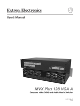
The MKP 2000 remote control panel should be installed in a standard, 2-gang electrical wall
box (see figure 3). In figure 3, the MKP is installed in a wall. It could also be installed in a
desk, a podium, or any other convenient location.
The procedures provided here assume that the electrical wall boxes and the cables have
been installed for the system (see Rear Panel and Side Panel Connections starting on
page9 to terminate the cables).
Installation
The MKP 2000 remote control panel should be installed in a standard, 2-gang electrical wall
box (see figure 3). The diagram shows the MKP installed in a wall. It could also be installed
in a desk, a podium, or any other convenient location.
The procedures provided here assume that the electrical wall boxes and the cables have
been installed for the system (see Rear Panel and Side Panel Connections to terminate
the cables).
MKP 200
0
4 5 6
1 2 3
7
8
9
BACK
0
CANC
EL
INPUT OUTPUT
TAKE
R
Figure 3. MKP Mounted in a Wall Box
UL Requirements for Wall Box Installation
The following Underwriters Laboratories (UL) requirements pertain to the installation of the
MKP 2000 into a wall or furniture (see figure 3).
1. These units are not to be connected to a centralized DC power source or used beyond
their rated voltage range.
2. These units must be installed in UL listed junction boxes.
3. These units must be installed with conduit in accordance with the National Electrical
Code.
figure 3

MKP 2000 • Installation6
Installation Procedures
The MKPs are mounted into a wall, furniture, or any other convenient location. Follow the
instructions appropriate to the mounting option you have selected.
ATTENTION:
• The control panel must be installed into a UL approved electrical wall box.
• Le panneau de contrôle doit être installé dans un boîtier mural approuvé UL.
• Follow all national and local building and electrical codes that apply to the
installation site.
• Respectez tous les codes électriques et du bâtiment, nationaux et locaux, qui
s’appliquent au site de l’installation.
Preparing the site and installing the mounting bracket (mud ring) or
wall box
Choose a location that allows cable runs without interference. Allow enough depth for both
the wall box and the cables. You may need to install the cables into the wall, furniture, or
conduits before installing the control panel.
The installation must conform to national and local electrical codes and to the equipment’s
size requirements. A cutout template that shows the cutout requirement for the circuitry
enclosure on the rear of the control panel is provided in Reference Information (see
page45).
ATTENTION:
• The templates provided in this manual are not to scale. Use these diagrams only for
reference.
• Les modèles fournis dans ce manuel ne sont pas à l’échelle. Utilisez ces schémas
seulement comme une référence.
• Extron provides one mud ring with each control panel. However, you may choose
to use a wall box. Because the tolerances on electrical boxes are very loose, Extron
recommends that you measure the actual box that you plan to use before making
any precise cuts.
• Extron fournit un cadre d’installation avec chaque panneau de contrôle. Cependant,
vous pouvez choisir d’utiliser un boîtier mural. Les limites des boîtiers électriques
étant très mal définies, Extron recommande que vous mesuriez le boîtier que vous
pensez utiliser avant toute découpe.
Extron recommends installation using a UL listed wall box (available from Extron) for most
mounting options, but you can use the included mounting brackets (mud rings) instead.
NOTES:
• Before using the mud rings, verify that the installation conforms to national and local
electrical codes.
• The electrical box must be at least 2.5 inches (7 cm) deep to accommodate the
MKP rear enclosure.
• To meet the UL listing requirements, the MKP must be installed in a wall box.

MKP 2000 • Installation 7
Install the mud ring or wall box as follows:
1. If you are using a mud ring, use the template that came with the mud ring. Cut out
the indicated center portion.
If you are using a wall box, refer to the cutout template in Reference Information
(see page45) that corresponds to the faceplate you are using; and cut out the center
portion of it as indicated on the template.
2. Place the wall box or mud ring against the installation surface or measure the cut
according to the template, and mark the guidelines for the opening on the wall or
furniture.
3. Cut out the wall or furniture material from the marked area.
4. Check the size of the opening by inserting the wall box, mud ring, or control panel into
it. The box or mud ring (if used) and/or control panel should fit easily into the opening.
Enlarge or smooth the edges of the opening if needed.
5. If you are using a wall box, feed cables through the wall box punch-out holes, and
secure them with cable clamps to provide strain relief.
6. Exposed cable shields (braids or foil) are potential sources of short circuits. Trim back
and/or insulate shields with heat shrink (see figure 4).
ATTENTION:
• To prevent short circuits, cut back the outer foil shield to the point where the
cable exits the cable clamp. Both braided and foil shields should be connected
to an equipment ground at the other end of the cable.
• Afin d’éviter les court circuits, réduisez le blindage en aluminium extérieur
jusqu’à ce que le câble sorte de la cosse de câble. Le blindage tressé et le
blindage en aluminium devraient être connectés à la masse d’un équipement à
l’autre bout du câble.
Installation
Cable
Cable
Clamp
Wall Stud
Foil
Shield
Screws or Nails
Screw
Braided
Shield
Figure 4. Grounding Outer Braided and Foil Shields
7. If you are using a mud ring, follow the directions, if any, that came with the mud ring to
attach the clips that fasten it to the wall or furniture (see figure 5 on the next page).
NOTE: To meet the UL listing requirements, the MKP device must be installed in a
wall box.
figure 4

MKP 2000 • Installation8
MKP
2000
4 5
6
1 2
3
7 8 9
BACK 0
CANCE
L
INPUT OUT
PUT
TAK
E
R
Detail A
0.75" #6-32 Screw
Backing Clip
Backing Clip
Sheet Rock
Sheet Rock
Mounting Bracket
Mounting Bracket
Detail B
1.25" #6-32 Screw
Backing clip can
be in either orientation.
See Detail A or Detail B.
Extron
MKP 2000
Figure 5. Attaching a Mud Ring to a Wall
• If using a wall box, insert the wall box into the opening; and attach it to the wall stud
or furniture with nails or screws, leaving the front edge flush with the outer wall or
furniture surface (see figure 6).
• If attaching the wall box to wood, use four #8 or #10 screws or 10-penny nails. A
minimum of ½ inch (1.3 cm) of screw threads must penetrate the wood.
• If attaching the wall box to metal studs or furniture, use four #8 or #10 self-tapping
sheet metal screws or machine bolts with matching nuts.
Flush with
Wall Surface
Screws or Nails
Wall Stud
Wall Box
Figure 6. Attaching a Wall Box to a Wall Stud
8. Connect the Ethernet cable, RS-232 cable, or both cables (as appropriate) and the
power cable, and test the MKP before fastening the control panel into the wall box (see
Rear Panel and Side Panel Connections on page9 for details).
NOTE: The rear panel connectors will be inaccessible after installation.
figure 5
figure 6

MKP 2000 • Installation 9
Mounting the MKP to the mounting bracket (mud ring) or wall box
1. Remove power from the control panel by disconnecting the power supply.
2. Place the control panel through the opening in the wall or furniture and through the mud
ring or into the wall box. Take care not to damage the cables, which fit behind the MKP,
at the back of the wall box.
3. Mount the MKP faceplate to the mud ring or wall box with machine screws (see
figure 7).
MKP 200
0
4 5 6
1 2 3
7
8
9
BACK
0
CANC
EL
INPUT OUTPUT
TAKE
R
Figure 7. Mounting the MKP to the Wall Box
4. Reconnect the power supply and restore power.
Rear Panel and Side Panel Connections
All connectors are on the rear or side of the MKP (see figure 8). These connectors will be
inaccessible once the MKP is installed.
Tx
HOST
RS-232
SWITCH
RS-232
Rx
GND
Tx
Rx
GND
12 VDC
LAN
PRESS TAB WITH
TWEEKER TO REMOVE
GND
Tx
HOST
RS-232
SWITCH
RS-232
Rx
GND
Tx
Rx
GND
12 VDC
LAN
PRESS TAB WITH
TWEEKER TO REMOVE
GND
11
2
2
3
3
4
4
Figure 8. MKP Rear and Side Panels
1
LAN (Ethernet) port — If desired, connect a Category (CAT) 5e or higher (network)
cable between this connector and either the matrix switcher to be controlled or to an
Ethernet local area network (LAN).
See TP Cable Termination and Recommendations on page12, to properly wire
the RJ-45 connector for your application.
figure 7
figure 8

MKP 2000 • Installation10
Ethernet connection indicators — The Link and Activity LEDs
indicate the status of the Ethernet connection (see figure 8 on the
previous page).
• The green Link LED indicates that the MKP is properly connected to
an Ethernet LAN. This LED should light steadily.
• The yellow Activity LED indicates transmission of data packets on the RJ-45
connector. This LED should flicker as the MKP communicates.
2
Host RS-232 port — If desired, connect a host computer or control system to this
3-pole, 3.5 mm, RS-232 connector (see figure 9).
Pin Function
TX
RX
Gnd
Transmit data
Receive data
Signal ground
Tx
HOST
RS-232
SWITCH
RS-232
Rx
GND
Tx
Rx
GND
Figure 9. RS-232 Connector
3
Switch RS-232 port — If desired, connect a cable between this 3-pole, 3.5 mm,
RS-232 connector and a matrix switcher (see figure 9).
4
Power connector — Plug the included external 12 VDC power supply into this
2-pole captive screw connector (see Power Supply Wiring on page13, to wire the
connector.
Control Connections
The MKP has two RS-232 ports — a Host port (
2
) and a Switch port (
3
) — and an
Ethernet (LAN) port (
1
) (see figure 8 on the previous page).
An MKP control panel can be directly cross-connected to any Extron matrix switcher
through the switcher RS-232 port (see figure 14 on page12 for pin assignments for
the RS-232 cable). A control system or host computer can be connected via the MKP
host RS-232 port. Additional MKPs can be connected to the matrix switcher through the
MKP that is RS-232 connected (the primary MKP). The additional (secondary) MKPs are
connected to the primary MKP via the primary MKP Ethernet port. An example of this type
of configuration is shown in figure 10.
Ethernet
MKP 2000
MKP 2000
MKP 2000
MKP 2000
MKP 2000
Host
RS-232 Port
Switcher
RS-232 Port
Ethernet
Control
System
Matrix Switcher
MKP 2000
4 5 6
1 2 3
7 8 9
BACK 0
CANCEL
INPUT OUTPUT
TAKE
MKP 2000
4 5 6
1 2 3
7 8 9
BACK 0
CANCEL
INPUT OUTPUT
TAKE
MKP 2000
4 5 6
1 2 3
7 8 9
BACK 0
CANCEL
INPUT OUTPUT
TAKE
MKP 2000
4 5 6
1 2 3
7 8 9
BACK 0
CANCEL
INPUT OUTPUT
TAKE
MKP 2000
4 5 6
1 2 3
7 8 9
BACK 0
CANCEL
INPUT OUTPUT
TAKE
I
N
P
U
T
S
CONTROL
O
U
T
P
U
T
S
I/O
1 2 3 4 5 6 7 8 9 10 11 12
13 14 15 16 17 18 19 20 21 22 23 24
1 2 3 4 5 6 7 8 9 10 11 12
13 14 15 16 17 18 19 20 21 22 23 24
MAV 2400 SERIES SWITCHER
Figure 10. MKP Connection Using the RS-232 Port
figure 9
figure 10
RJ-45
Port
Link
LED
Activity
LED

MKP 2000 • Installation 11
An MKP control panel can be directly connected to any Ethernet-enabled matrix switcher
via the switcher Ethernet port (see figure 11) using a TP (network) cable that is wired as a
crossover cable (see TP Cable Termination and Recommendations on page12, to
properly wire the cable).
MKP 2000
Crossover
Cable
LAN Port
Matrix Switcher
MKP 2000
456
123
789
BACK 0
CANCEL
INPUT OUTPUT
TAKE
I
N
P
U
T
S
CONTROL
O
U
T
P
U
T
S
I/O
1 2 3 4 5 6 7 8 9 10 11 12
13 14 15 16 17 18 19 20 21 22 23 24
1 2 3 4 5 6 7 8 9 10 11 12
13 14 15 16 17 18 19 20 21 22 23 24
MAV 2400 SERIES SWITCHER
Figure 11. Direct MKP Connection Via the LAN Port
Any number of control panels can be connected, as part of a network, to any Ethernet-
enabled matrix switcher via the switcher Ethernet port (see figure 12). All TP cables in this
example are wired as patch (straight-through) cables.
Ethernet
MKP 2000
MKP 2000
MKP 2000
PC
Patch
Cable
Patch
Cable
Matrix Switcher
MKP 2000
4 5 6
1 2 3
7 8 9
BACK 0
CANCEL
INPUT OUTPUT
TAKE
MKP 2000
4 5 6
1 2 3
7 8 9
BACK 0
CANCEL
INPUT OUTPUT
TAKE
MKP 2000
4 5 6
1 2 3
7 8 9
BACK 0
CANCEL
INPUT OUTPUT
TAKE
I
N
P
U
T
S
CONTROL
O
U
T
P
U
T
S
I/O
1 2 3 4 5 6 7 8 9 10 11 12
13 14 15 16 17 18 19 20 21 22 23 24
1 2 3 4 5 6 7 8 9 10 11 12
13 14 15 16 17 18 19 20 21 22 23 24
MAV 2400 SERIES SWITCHER
Figure 12. Network MKP Connection Using the LAN Port
RS-232 Cable Termination
Each MKP control panel has two RS-232 ports that are connected using 3.5 mm, 3-pole
direct insertion connectors. Wire the connectors as follows:
NOTE: The total cable length between an MKP control panel and a matrix switcher
should not exceed 100 feet (30 m).
1. Choose a cable such as the Extron Comm-Link cable (see figure 13, on the next page,
for the wire specifications for Comm-Link cable). Colors may vary from this example.
2. Trim approximately 1.5 inches (3.8 cm) of the cable jacket to expose the four insulated
wires and a bare drain wire (silver-colored).
3. Cut off the foil shield and discard it.
4. Strip ¼ inch (0.6 cm) of insulation from any three of the four wires (not including the
drain [unshielded] wire).
5. Twist the strands of each wire, insert the strands into the direct insertion connector, and
tighten the captive screws.
figure 11
figure 12

MKP 2000 • Installation12
Extron Control System Comm-Link cable
Wire specifications for Extron Comm-Link cable (see figure 13) are as follows:
• A (red) = 18 American Wire Gauge (AWG)
• B (violet or blue) = 22 AWG (grouped and shielded)
• C (white) = 22 AWG
• D (drain) = 24 AWG
• E (black) = 18 AWG
NOTE: Comm-Link cable was designed for use with MKP control panels.
SuperFlex Plenum
Jacket
Fiber Wrap
Two 22 AWG
(White and Violet or Blue)
One 24 AWG
Tinned Copper Drain Wire
(foil-shielded group)
B, C
D
Two 18 AWG
(Red and Black)
A, E
Figure 13. Extron Comm-Link Cable
For RS- 232 pin assignments, see figure 14.
Pin Switcher RS-232 MKP RS-232
1 – –
2 Tx Rx
3 Rx Tx
4 –
–
5 Gnd Gnd
6 – –
7 – –
8 – –
9 – –
Figure 14. RS-232 Cross-connection Table
TP Cable Termination and Recommendations
It is vital that you use the correct Ethernet cables, and that they be properly terminated with
the correct pinout. Ethernet links use Category (CAT) 5e or CAT 6, unshielded twisted pair
(UTP) or shielded twisted pair (STP) cables, terminated with RJ-45 connectors. Ethernet
cables are limited to a length of 328 feet (100 m).
ATTENTION:
• Do not use standard telephone cables. Telephone cables do not support Ethernet
or Fast Ethernet.
• Ne pas utiliser de câbles téléphone standard. Les câbles de téléphone ne sont pas
compatibles avec les liaisons Ethernet ou Fast Ethernet.
• Do not stretch or bend cables. This can cause transmission errors.
• Ne pas étirer ou plier les câbles. Cela pourrait provoquer des erreurs de
transmission.
figure 13
figure 14
Page is loading ...
Page is loading ...
Page is loading ...
Page is loading ...
Page is loading ...
Page is loading ...
Page is loading ...
Page is loading ...
Page is loading ...
Page is loading ...
Page is loading ...
Page is loading ...
Page is loading ...
Page is loading ...
Page is loading ...
Page is loading ...
Page is loading ...
Page is loading ...
Page is loading ...
Page is loading ...
Page is loading ...
Page is loading ...
Page is loading ...
Page is loading ...
Page is loading ...
Page is loading ...
Page is loading ...
Page is loading ...
Page is loading ...
Page is loading ...
Page is loading ...
Page is loading ...
Page is loading ...
Page is loading ...
Page is loading ...
Page is loading ...
/