Page is loading ...

KeyStone Architecture
Literature Number: SPRUGZ3A
May 2011
External Memory Interface (EMIF16)
User Guide

ø-ii KeyStone Architecture External Memory Interface (EMIF16) User Guide SPRUGZ3A—May 2011
www.ti.com
Submit Documentation Feedback
Release History
Release Date Chapter/Topic Description/Comments
Revision A May 2011 ‘‘Introduction’’ In the ‘‘Features’’ section, updated the description of features not supported and
added additional information about the 64MB limit.
1.0 January 2011 All Initial Release

Contents
SPRUGZ3A—May 2011 KeyStone Architecture External Memory Interface (EMIF16) User Guide ø-iii
Submit Documentation Feedback
www.ti.com
Contents
Release History. . . . . . . . . . . . . . . . . . . . . . . . . . . . . . . . . . . . . . . . . . . . . . . . . . . . . . . . . . . . . . . . . . . . . . . . . . . . . . . . . . . . . . . . . . . . . . . . . . . . . . . ø-ii
List of Tables . . . . . . . . . . . . . . . . . . . . . . . . . . . . . . . . . . . . . . . . . . . . . . . . . . . . . . . . . . . . . . . . . . . . . . . . . . . . . . . . . . . . . . . . . . . . . . . . . . . . . . . . . ø-v
List of Figures . . . . . . . . . . . . . . . . . . . . . . . . . . . . . . . . . . . . . . . . . . . . . . . . . . . . . . . . . . . . . . . . . . . . . . . . . . . . . . . . . . . . . . . . . . . . . . . . . . . . . . . . ø-vi
Preface ø-vii
About This Manual. . . . . . . . . . . . . . . . . . . . . . . . . . . . . . . . . . . . . . . . . . . . . . . . . . . . . . . . . . . . . . . . . . . . . . . . . . . . . . . .ø-vii
Notational Conventions. . . . . . . . . . . . . . . . . . . . . . . . . . . . . . . . . . . . . . . . . . . . . . . . . . . . . . . . . . . . . . . . . . . . . . . . . . .ø-vii
Related Documentation from Texas Instruments . . . . . . . . . . . . . . . . . . . . . . . . . . . . . . . . . . . . . . . . . . . . . . . . . . ø-viii
Trademarks. . . . . . . . . . . . . . . . . . . . . . . . . . . . . . . . . . . . . . . . . . . . . . . . . . . . . . . . . . . . . . . . . . . . . . . . . . . . . . . . . . . . . . ø-viii
Chapter 1
Introduction 1-1
1.1 Purpose of the Peripheral . . . . . . . . . . . . . . . . . . . . . . . . . . . . . . . . . . . . . . . . . . . . . . . . . . . . . . . . . . . . . . . . . . . . . . 1-2
1.2 Features . . . . . . . . . . . . . . . . . . . . . . . . . . . . . . . . . . . . . . . . . . . . . . . . . . . . . . . . . . . . . . . . . . . . . . . . . . . . . . . . . . . . . . . 1-2
Chapter 2
Architecture 2-1
2.1 EMIF16 Signal Descriptions. . . . . . . . . . . . . . . . . . . . . . . . . . . . . . . . . . . . . . . . . . . . . . . . . . . . . . . . . . . . . . . . . . . . . 2-2
2.2 Memory Organization. . . . . . . . . . . . . . . . . . . . . . . . . . . . . . . . . . . . . . . . . . . . . . . . . . . . . . . . . . . . . . . . . . . . . . . . . . 2-3
2.3 Supported Modes. . . . . . . . . . . . . . . . . . . . . . . . . . . . . . . . . . . . . . . . . . . . . . . . . . . . . . . . . . . . . . . . . . . . . . . . . . . . . . 2-3
2.4 Configuring the EMIF16 for Asynchronous Access. . . . . . . . . . . . . . . . . . . . . . . . . . . . . . . . . . . . . . . . . . . . . . . 2-3
2.5 ASRAM/NOR Flash Interface . . . . . . . . . . . . . . . . . . . . . . . . . . . . . . . . . . . . . . . . . . . . . . . . . . . . . . . . . . . . . . . . . . . . 2-4
2.5.1 EMIF16 Signal Description – ASRAM/NOR Flash . . . . . . . . . . . . . . . . . . . . . . . . . . . . . . . . . . . . . . . . . . . . . . . . . . . . . .2-5
2.5.2 Programmable EMIF16 Parameters . . . . . . . . . . . . . . . . . . . . . . . . . . . . . . . . . . . . . . . . . . . . . . . . . . . . . . . . . . . . . . . . . .2-6
2.5.3 EMIF16 Truth Table . . . . . . . . . . . . . . . . . . . . . . . . . . . . . . . . . . . . . . . . . . . . . . . . . . . . . . . . . . . . . . . . . . . . . . . . . . . . . . . . . 2-6
2.5.4 Switching Waveforms . . . . . . . . . . . . . . . . . . . . . . . . . . . . . . . . . . . . . . . . . . . . . . . . . . . . . . . . . . . . . . . . . . . . . . . . . . . . . . .2-7
2.5.4.1 Asynchronous Reads . . . . . . . . . . . . . . . . . . . . . . . . . . . . . . . . . . . . . . . . . . . . . . . . . . . . . . . . . . . . . . . . . . . . . . . . . 2-7
2.5.4.2 Asynchronous Writes . . . . . . . . . . . . . . . . . . . . . . . . . . . . . . . . . . . . . . . . . . . . . . . . . . . . . . . . . . . . . . . . . . . . . . . . .2-8
2.5.5 Select Strobe Mode . . . . . . . . . . . . . . . . . . . . . . . . . . . . . . . . . . . . . . . . . . . . . . . . . . . . . . . . . . . . . . . . . . . . . . . . . . . . . . . . .2-9
2.5.5.1 Asynchronous Reads in SS Mode . . . . . . . . . . . . . . . . . . . . . . . . . . . . . . . . . . . . . . . . . . . . . . . . . . . . . . . . . . . . .2-10
2.5.5.2 Asynchronous Writes in SS Mode. . . . . . . . . . . . . . . . . . . . . . . . . . . . . . . . . . . . . . . . . . . . . . . . . . . . . . . . . . . . .2-11
2.5.6 WE Strobe Mode . . . . . . . . . . . . . . . . . . . . . . . . . . . . . . . . . . . . . . . . . . . . . . . . . . . . . . . . . . . . . . . . . . . . . . . . . . . . . . . . . . .2-12
Chapter 3
Operating Modes 3-1
3.1 NAND Flash Mode . . . . . . . . . . . . . . . . . . . . . . . . . . . . . . . . . . . . . . . . . . . . . . . . . . . . . . . . . . . . . . . . . . . . . . . . . . . . . 3-2
3.1.1 Connecting to NAND Flash . . . . . . . . . . . . . . . . . . . . . . . . . . . . . . . . . . . . . . . . . . . . . . . . . . . . . . . . . . . . . . . . . . . . . . . . . .3-2
3.2 Configuring EMIF16 in NAND Flash Mode . . . . . . . . . . . . . . . . . . . . . . . . . . . . . . . . . . . . . . . . . . . . . . . . . . . . . . . 3-3
3.3 EMIF16 Signal Description – NAND Flash. . . . . . . . . . . . . . . . . . . . . . . . . . . . . . . . . . . . . . . . . . . . . . . . . . . . . . . . 3-3
3.4 Using ALE and CLE . . . . . . . . . . . . . . . . . . . . . . . . . . . . . . . . . . . . . . . . . . . . . . . . . . . . . . . . . . . . . . . . . . . . . . . . . . . . . 3-4
3.5 NAND Read and Program Operations . . . . . . . . . . . . . . . . . . . . . . . . . . . . . . . . . . . . . . . . . . . . . . . . . . . . . . . . . . . 3-4
3.6 Checking the Status of Operation. . . . . . . . . . . . . . . . . . . . . . . . . . . . . . . . . . . . . . . . . . . . . . . . . . . . . . . . . . . . . . . 3-5
3.7 ECC Support . . . . . . . . . . . . . . . . . . . . . . . . . . . . . . . . . . . . . . . . . . . . . . . . . . . . . . . . . . . . . . . . . . . . . . . . . . . . . . . . . . . 3-5
3.8 Extended Wait Mode. . . . . . . . . . . . . . . . . . . . . . . . . . . . . . . . . . . . . . . . . . . . . . . . . . . . . . . . . . . . . . . . . . . . . . . . . . . 3-9
3.9 Data Bus Parking. . . . . . . . . . . . . . . . . . . . . . . . . . . . . . . . . . . . . . . . . . . . . . . . . . . . . . . . . . . . . . . . . . . . . . . . . . . . . . . 3-9
3.10 Interrupt Support. . . . . . . . . . . . . . . . . . . . . . . . . . . . . . . . . . . . . . . . . . . . . . . . . . . . . . . . . . . . . . . . . . . . . . . . . . . . . 3-9
3.11 NOR Flash Page Mode . . . . . . . . . . . . . . . . . . . . . . . . . . . . . . . . . . . . . . . . . . . . . . . . . . . . . . . . . . . . . . . . . . . . . . .3-10
3.12 Reset Considerations . . . . . . . . . . . . . . . . . . . . . . . . . . . . . . . . . . . . . . . . . . . . . . . . . . . . . . . . . . . . . . . . . . . . . . . .3-10

Contents
ø-iv KeyStone Architecture External Memory Interface (EMIF16) User Guide SPRUGZ3A—May 2011
Submit Documentation Feedback
www.ti.com
Chapter 4
Registers 4-1
4.1 Registers Overview . . . . . . . . . . . . . . . . . . . . . . . . . . . . . . . . . . . . . . . . . . . . . . . . . . . . . . . . . . . . . . . . . . . . . . . . . . . . 4-2
4.2 Revision Code and Status Register (RCSR) . . . . . . . . . . . . . . . . . . . . . . . . . . . . . . . . . . . . . . . . . . . . . . . . . . . . . . . 4-3
4.3 Async Wait Cycle Config Register (AWCCR). . . . . . . . . . . . . . . . . . . . . . . . . . . . . . . . . . . . . . . . . . . . . . . . . . . . . . 4-4
4.4 Async 1 Config Register (A1CR) . . . . . . . . . . . . . . . . . . . . . . . . . . . . . . . . . . . . . . . . . . . . . . . . . . . . . . . . . . . . . . . . . 4-6
4.5 Async 2 Config Register (A2CR) . . . . . . . . . . . . . . . . . . . . . . . . . . . . . . . . . . . . . . . . . . . . . . . . . . . . . . . . . . . . . . . . . 4-7
4.6 Async 3 Config Register (A3CR) . . . . . . . . . . . . . . . . . . . . . . . . . . . . . . . . . . . . . . . . . . . . . . . . . . . . . . . . . . . . . . . . . 4-7
4.7 Async 4 Config Register (A4CR) . . . . . . . . . . . . . . . . . . . . . . . . . . . . . . . . . . . . . . . . . . . . . . . . . . . . . . . . . . . . . . . . . 4-7
4.8 Interrupt Raw Register (IRR) . . . . . . . . . . . . . . . . . . . . . . . . . . . . . . . . . . . . . . . . . . . . . . . . . . . . . . . . . . . . . . . . . . . . 4-8
4.9 Interrupt Masked Register (IMR) . . . . . . . . . . . . . . . . . . . . . . . . . . . . . . . . . . . . . . . . . . . . . . . . . . . . . . . . . . . . . . . . 4-9
4.10 Interrupt Mask Set Register (IMSR). . . . . . . . . . . . . . . . . . . . . . . . . . . . . . . . . . . . . . . . . . . . . . . . . . . . . . . . . . . .4-10
4.11 Interrupt Mask Clear Register (IMCR). . . . . . . . . . . . . . . . . . . . . . . . . . . . . . . . . . . . . . . . . . . . . . . . . . . . . . . . . .4-11
4.12 NAND Flash Control Register (NANDFCR) . . . . . . . . . . . . . . . . . . . . . . . . . . . . . . . . . . . . . . . . . . . . . . . . . . . . .4-12
4.13 NAND Flash Status Register (NANDFSR) . . . . . . . . . . . . . . . . . . . . . . . . . . . . . . . . . . . . . . . . . . . . . . . . . . . . . .4-14
4.14 Page Mode Control Register (PMCR). . . . . . . . . . . . . . . . . . . . . . . . . . . . . . . . . . . . . . . . . . . . . . . . . . . . . . . . . .4-15
4.15 NAND Flash CS2 (CE0) 1-Bit ECC Register (NFECCCS2R). . . . . . . . . . . . . . . . . . . . . . . . . . . . . . . . . . . . . . . .4-17
4.16 NAND Flash CS3 (CE1) 1-Bit ECC Register (NFECCCS3R). . . . . . . . . . . . . . . . . . . . . . . . . . . . . . . . . . . . . . . .4-18
4.17 NAND Flash CS4 (CE2) 1-Bit ECC Register (NFECCCS4R). . . . . . . . . . . . . . . . . . . . . . . . . . . . . . . . . . . . . . . .4-18
4.18 NAND Flash CS5 (CE3) 1-Bit ECC Register (NFECCCS5R). . . . . . . . . . . . . . . . . . . . . . . . . . . . . . . . . . . . . . . .4-18
4.19 NAND Flash 4-Bit ECC Load Register (NANDF4BECCLR). . . . . . . . . . . . . . . . . . . . . . . . . . . . . . . . . . . . . . . .4-18
4.20 NAND Flash 4-Bit ECC 1 Register (NANDF4BECC1R) . . . . . . . . . . . . . . . . . . . . . . . . . . . . . . . . . . . . . . . . . . .4-19
4.21 NAND Flash 4-Bit ECC 2 Register (NANDF4BECC2R) . . . . . . . . . . . . . . . . . . . . . . . . . . . . . . . . . . . . . . . . . . .4-20
4.22 NAND Flash 4-Bit ECC 3 Register (NANDF4BECC3R) . . . . . . . . . . . . . . . . . . . . . . . . . . . . . . . . . . . . . . . . . . .4-21
4.23 NAND Flash 4-Bit ECC 4 Register (NANDF4BECC4R) . . . . . . . . . . . . . . . . . . . . . . . . . . . . . . . . . . . . . . . . . . .4-22
4.24 NAND Flash Error Address 1 Register (NANDFEA1R) . . . . . . . . . . . . . . . . . . . . . . . . . . . . . . . . . . . . . . . . . . .4-23
4.25 NAND Flash Error Address 2 Register (NANDFEA2R) . . . . . . . . . . . . . . . . . . . . . . . . . . . . . . . . . . . . . . . . . . .4-24
4.26 NAND Flash Error Value 1 Register (NANDFEV1R) . . . . . . . . . . . . . . . . . . . . . . . . . . . . . . . . . . . . . . . . . . . . .4-25
4.27 NAND Flash Error Value 2 Register (NANDFEV2R) . . . . . . . . . . . . . . . . . . . . . . . . . . . . . . . . . . . . . . . . . . . . .4-26
Index IX-1

List of Tables
SPRUGZ3A—May 2011 KeyStone Architecture External Memory Interface (EMIF16) User Guide ø-v
Submit Documentation Feedback
www.ti.com
List of Tables
Table 2-1 EMIF16 Signal Descriptions . . . . . . . . . . . . . . . . . . . . . . . . . . . . . . . . . . . . . . . . . . . . . . . . . . . . . . . . . . . . . . . . . . . . . . . . . . . . . . . . . . . . . . 2-2
Table 2-2 ASRAM/NOR Flash Interface Signals . . . . . . . . . . . . . . . . . . . . . . . . . . . . . . . . . . . . . . . . . . . . . . . . . . . . . . . . . . . . . . . . . . . . . . . . . . . . . . 2-5
Table 2-3 Control Signal Truth Table . . . . . . . . . . . . . . . . . . . . . . . . . . . . . . . . . . . . . . . . . . . . . . . . . . . . . . . . . . . . . . . . . . . . . . . . . . . . . . . . . . . . . . . 2-6
Table 3-1 NAND interface signal description . . . . . . . . . . . . . . . . . . . . . . . . . . . . . . . . . . . . . . . . . . . . . . . . . . . . . . . . . . . . . . . . . . . . . . . . . . . . . . . 3-3
Table 3-2 CE0 Addressing when EMIFA11 and EMIFA12 are used as ALE and CLE respectively . . . . . . . . . . . . . . . . . . . . . . . . . . . . . . . . 3-4
Table 3-3 4-bit ECC calculation bits in NAND Flash Control Register . . . . . . . . . . . . . . . . . . . . . . . . . . . . . . . . . . . . . . . . . . . . . . . . . . . . . . . . . 3-6
Table 3-4 Interrupt status and control bits . . . . . . . . . . . . . . . . . . . . . . . . . . . . . . . . . . . . . . . . . . . . . . . . . . . . . . . . . . . . . . . . . . . . . . . . . . . . . . . . 3-10
Table 4-1 EMIF16 Registers . . . . . . . . . . . . . . . . . . . . . . . . . . . . . . . . . . . . . . . . . . . . . . . . . . . . . . . . . . . . . . . . . . . . . . . . . . . . . . . . . . . . . . . . . . . . . . . . 4-2
Table 4-2 Revision Code and Status Register (RCSR) Field Descriptions . . . . . . . . . . . . . . . . . . . . . . . . . . . . . . . . . . . . . . . . . . . . . . . . . . . . . . 4-3
Table 4-3 Async Wait Cycle Config Register (AWCCR) Description . . . . . . . . . . . . . . . . . . . . . . . . . . . . . . . . . . . . . . . . . . . . . . . . . . . . . . . . . . . 4-4
Table 4-4 Async 1 Config Register (A1CR) Description . . . . . . . . . . . . . . . . . . . . . . . . . . . . . . . . . . . . . . . . . . . . . . . . . . . . . . . . . . . . . . . . . . . . . . 4-6
Table 4-5 Interrupt Raw Register (IRR) Description. . . . . . . . . . . . . . . . . . . . . . . . . . . . . . . . . . . . . . . . . . . . . . . . . . . . . . . . . . . . . . . . . . . . . . . . . . 4-8
Table 4-6 Interrupt Masked Register (IMR) Description. . . . . . . . . . . . . . . . . . . . . . . . . . . . . . . . . . . . . . . . . . . . . . . . . . . . . . . . . . . . . . . . . . . . . . 4-9
Table 4-7 Interrupt Mask Set Register (IMSR) Description . . . . . . . . . . . . . . . . . . . . . . . . . . . . . . . . . . . . . . . . . . . . . . . . . . . . . . . . . . . . . . . . . . 4-10
Table 4-8 Interrupt Mask Clear Register (IMCR) Description . . . . . . . . . . . . . . . . . . . . . . . . . . . . . . . . . . . . . . . . . . . . . . . . . . . . . . . . . . . . . . . . 4-11
Table 4-9 NAND Flash Control Register (NANDFCR) Description. . . . . . . . . . . . . . . . . . . . . . . . . . . . . . . . . . . . . . . . . . . . . . . . . . . . . . . . . . . .4-12
Table 4-10 NAND Flash Status Register (NANDFSR) Description . . . . . . . . . . . . . . . . . . . . . . . . . . . . . . . . . . . . . . . . . . . . . . . . . . . . . . . . . . . . . 4-14
Table 4-11 Page Mode Control Register (PMCR) Description . . . . . . . . . . . . . . . . . . . . . . . . . . . . . . . . . . . . . . . . . . . . . . . . . . . . . . . . . . . . . . . .4-15
Table 4-12 NAND Flash CS2 (CE0) 1-Bit ECC Register (NFECCCS2R) Description . . . . . . . . . . . . . . . . . . . . . . . . . . . . . . . . . . . . . . . . . . . . . .4-17
Table 4-13 NAND Flash 4-Bit ECC Load Register (NANDF4BECCLR) Description . . . . . . . . . . . . . . . . . . . . . . . . . . . . . . . . . . . . . . . . . . . . . .4-18
Table 4-14 NAND Flash 4-Bit ECC 1 Register (NANDF4BECC1R) Description . . . . . . . . . . . . . . . . . . . . . . . . . . . . . . . . . . . . . . . . . . . . . . . . . .4-19
Table 4-15 NAND Flash 4-Bit ECC 2 Register (NANDF4BECC2R) Description . . . . . . . . . . . . . . . . . . . . . . . . . . . . . . . . . . . . . . . . . . . . . . . . . .4-20
Table 4-16 NAND Flash 4-Bit ECC 3 Register (NANDF4BECC3R) Description . . . . . . . . . . . . . . . . . . . . . . . . . . . . . . . . . . . . . . . . . . . . . . . . . .4-21
Table 4-17 NAND Flash 4-Bit ECC 4 Register (NANDF4BECC4R) Description . . . . . . . . . . . . . . . . . . . . . . . . . . . . . . . . . . . . . . . . . . . . . . . . . .4-22
Table 4-18 NAND Flash Error Address 1 Register (NANDFEA1R) Description. . . . . . . . . . . . . . . . . . . . . . . . . . . . . . . . . . . . . . . . . . . . . . . . . .4-23
Table 4-19 NAND Flash Error Address 2 Register (NANDFEA2R) Description. . . . . . . . . . . . . . . . . . . . . . . . . . . . . . . . . . . . . . . . . . . . . . . . . .4-24
Table 4-20 NAND Flash Error Value 1 Register (NANDFEV1R) Description . . . . . . . . . . . . . . . . . . . . . . . . . . . . . . . . . . . . . . . . . . . . . . . . . . . . 4-25
Table 4-21 NAND Flash Error Value 2 Register (NANDFEV2R) Description . . . . . . . . . . . . . . . . . . . . . . . . . . . . . . . . . . . . . . . . . . . . . . . . . . . . 4-26

List of Figures
ø-vi KeyStone Architecture External Memory Interface (EMIF16) User Guide SPRUGZ3A—May 2011
Submit Documentation Feedback
www.ti.com
List of Figures
Figure 2-1 Basic Block diagram for EMIF16 . . . . . . . . . . . . . . . . . . . . . . . . . . . . . . . . . . . . . . . . . . . . . . . . . . . . . . . . . . . . . . . . . . . . . . . . . . . . . . . . . . 2-2
Figure 2-2 Connecting to 16-bit ASRAM (see note below). . . . . . . . . . . . . . . . . . . . . . . . . . . . . . . . . . . . . . . . . . . . . . . . . . . . . . . . . . . . . . . . . . . . 2-4
Figure 2-3 Connecting to 8-bit ASRAM. . . . . . . . . . . . . . . . . . . . . . . . . . . . . . . . . . . . . . . . . . . . . . . . . . . . . . . . . . . . . . . . . . . . . . . . . . . . . . . . . . . . . . 2-5
Figure 2-4 Asynchronous Read Timing Diagram. . . . . . . . . . . . . . . . . . . . . . . . . . . . . . . . . . . . . . . . . . . . . . . . . . . . . . . . . . . . . . . . . . . . . . . . . . . . . 2-8
Figure 2-5 Asynchronous Write Timing Diagram . . . . . . . . . . . . . . . . . . . . . . . . . . . . . . . . . . . . . . . . . . . . . . . . . . . . . . . . . . . . . . . . . . . . . . . . . . . . 2-9
Figure 2-6 Asynchronous Read Cycle (Select Strobe mode) . . . . . . . . . . . . . . . . . . . . . . . . . . . . . . . . . . . . . . . . . . . . . . . . . . . . . . . . . . . . . . . . .2-11
Figure 2-7 Write Cycle (Select Strobe Mode). . . . . . . . . . . . . . . . . . . . . . . . . . . . . . . . . . . . . . . . . . . . . . . . . . . . . . . . . . . . . . . . . . . . . . . . . . . . . . . .2-12
Figure 2-8 Asynchronous Writes (WE Strobe Mode) . . . . . . . . . . . . . . . . . . . . . . . . . . . . . . . . . . . . . . . . . . . . . . . . . . . . . . . . . . . . . . . . . . . . . . . . 2-13
Figure 2-9 Asynchronous Reads (WE Strobe Mode) . . . . . . . . . . . . . . . . . . . . . . . . . . . . . . . . . . . . . . . . . . . . . . . . . . . . . . . . . . . . . . . . . . . . . . . . .2-13
Figure 3-1 Connecting to 8-bit NAND Flash . . . . . . . . . . . . . . . . . . . . . . . . . . . . . . . . . . . . . . . . . . . . . . . . . . . . . . . . . . . . . . . . . . . . . . . . . . . . . . . . . 3-2
Figure 3-2 Connecting to 16-bit NAND Flash . . . . . . . . . . . . . . . . . . . . . . . . . . . . . . . . . . . . . . . . . . . . . . . . . . . . . . . . . . . . . . . . . . . . . . . . . . . . . . . . 3-2
Figure 3-3 1-bit ECC calculation for 8-bit NAND device . . . . . . . . . . . . . . . . . . . . . . . . . . . . . . . . . . . . . . . . . . . . . . . . . . . . . . . . . . . . . . . . . . . . . . 3-5
Figure 4-1 Revision Code and Status Register . . . . . . . . . . . . . . . . . . . . . . . . . . . . . . . . . . . . . . . . . . . . . . . . . . . . . . . . . . . . . . . . . . . . . . . . . . . . . . . 4-3
Figure 4-2 Async Wait Cycle Config Register . . . . . . . . . . . . . . . . . . . . . . . . . . . . . . . . . . . . . . . . . . . . . . . . . . . . . . . . . . . . . . . . . . . . . . . . . . . . . . . . 4-4
Figure 4-3 Async 1 Config Register (A1CR) . . . . . . . . . . . . . . . . . . . . . . . . . . . . . . . . . . . . . . . . . . . . . . . . . . . . . . . . . . . . . . . . . . . . . . . . . . . . . . . . . . 4-6
Figure 4-4 Interrupt Raw Register (IRR). . . . . . . . . . . . . . . . . . . . . . . . . . . . . . . . . . . . . . . . . . . . . . . . . . . . . . . . . . . . . . . . . . . . . . . . . . . . . . . . . . . . . . 4-8
Figure 4-5 Interrupt Masked Register (IMR). . . . . . . . . . . . . . . . . . . . . . . . . . . . . . . . . . . . . . . . . . . . . . . . . . . . . . . . . . . . . . . . . . . . . . . . . . . . . . . . . . 4-9
Figure 4-6 Interrupt Mask Set Register (IMSR) . . . . . . . . . . . . . . . . . . . . . . . . . . . . . . . . . . . . . . . . . . . . . . . . . . . . . . . . . . . . . . . . . . . . . . . . . . . . . .4-10
Figure 4-7 Interrupt Mask Clear Register (IMCR) . . . . . . . . . . . . . . . . . . . . . . . . . . . . . . . . . . . . . . . . . . . . . . . . . . . . . . . . . . . . . . . . . . . . . . . . . . . .4-11
Figure 4-8 NAND Flash Control Register (NANDFCR). . . . . . . . . . . . . . . . . . . . . . . . . . . . . . . . . . . . . . . . . . . . . . . . . . . . . . . . . . . . . . . . . . . . . . . .4-12
Figure 4-9 NAND Flash Status Register (NANDFSR) . . . . . . . . . . . . . . . . . . . . . . . . . . . . . . . . . . . . . . . . . . . . . . . . . . . . . . . . . . . . . . . . . . . . . . . . .4-14
Figure 4-10 Page Mode Control Register (PMCR) . . . . . . . . . . . . . . . . . . . . . . . . . . . . . . . . . . . . . . . . . . . . . . . . . . . . . . . . . . . . . . . . . . . . . . . . . . . .4-15
Figure 4-11 NAND Flash CS2 (CE0) 1-Bit ECC Register (NFECCCS2R) . . . . . . . . . . . . . . . . . . . . . . . . . . . . . . . . . . . . . . . . . . . . . . . . . . . . . . . . . . 4-17
Figure 4-12 NAND Flash 4-Bit ECC Load Register (NANDF4BECCLR) . . . . . . . . . . . . . . . . . . . . . . . . . . . . . . . . . . . . . . . . . . . . . . . . . . . . . . . . . .4-18
Figure 4-13 NAND Flash 4-Bit ECC 1 Register (NANDF4BECC1R) . . . . . . . . . . . . . . . . . . . . . . . . . . . . . . . . . . . . . . . . . . . . . . . . . . . . . . . . . . . . . .4-19
Figure 4-14 NAND Flash 4-Bit ECC 2 Register (NANDF4BECC2R) . . . . . . . . . . . . . . . . . . . . . . . . . . . . . . . . . . . . . . . . . . . . . . . . . . . . . . . . . . . . . .4-20
Figure 4-15 NAND Flash 4-Bit ECC 3 Register (NANDF4BECC3R) . . . . . . . . . . . . . . . . . . . . . . . . . . . . . . . . . . . . . . . . . . . . . . . . . . . . . . . . . . . . . .4-21
Figure 4-16 NAND Flash 4-Bit ECC 4 Register (NANDF4BECC4R) . . . . . . . . . . . . . . . . . . . . . . . . . . . . . . . . . . . . . . . . . . . . . . . . . . . . . . . . . . . . . .4-22
Figure 4-17 NAND Flash Error Address 1 Register (NANDFEA1R). . . . . . . . . . . . . . . . . . . . . . . . . . . . . . . . . . . . . . . . . . . . . . . . . . . . . . . . . . . . . .4-23
Figure 4-18 NAND Flash Error Address 2 Register (NANDFEA2R). . . . . . . . . . . . . . . . . . . . . . . . . . . . . . . . . . . . . . . . . . . . . . . . . . . . . . . . . . . . . .4-24
Figure 4-19 NAND Flash Error Value 1 Register (NANDFEV1R) . . . . . . . . . . . . . . . . . . . . . . . . . . . . . . . . . . . . . . . . . . . . . . . . . . . . . . . . . . . . . . . . 4-25
Figure 4-20 NAND Flash Error Value 2 Register (NANDFEV2R) . . . . . . . . . . . . . . . . . . . . . . . . . . . . . . . . . . . . . . . . . . . . . . . . . . . . . . . . . . . . . . . . 4-26

SPRUGZ3A—May 2011 KeyStone Architecture External Memory Interface (EMIF16) User Guide ø-vii
Submit Documentation Feedback
Preface
About This Manual
This document describes the operation of the External Memory Interface (EMIF16)
module in the KeyStone DSP family (refer to the device data manual for applicability
to a particular part). The EMIF16 module is accessible across all the cores and all system
masters that are not cores.
Notational Conventions
This document uses the following conventions:
• Commands and keywords are in boldface font.
• Arguments for which you supply values are in italic font.
• Terminal sessions and information the system displays are in
screen font.
• Information you must enter is in boldface screen font.
• Elements in square brackets ([ ]) are optional.
Notes use the following conventions:
Note—Means reader take note. Notes contain helpful suggestions or references
to material not covered in the publication.
The information in a caution or a warning is provided for your protection. Please read
each caution and warning carefully.
CAUTION—Indicates the possibility of service interruption if precautions are
not taken.
WARNING—Indicates the possibility of damage to equipment if precautions are
not taken.

ø-viii KeyStone Architecture External Memory Interface (EMIF16) User Guide SPRUGZ3A—May 2011
Submit Documentation Feedback
Preface
www.ti.com
Related Documentation from Texas Instruments
Trademarks
All brand names and trademarks mentioned in this document are the property of Texas Instruments Incorporated
or their respective owners, as applicable.
TMS320C6000 DSP and Instruction Set Reference Guide SPRU189
TMS320C6000 Programmer’s Guide. SPRU198
TMS320C6000 Code Composer Studio Forum Forum
C66x CorePac User Guide SPRUGW0

SPRUGZ3A—May 2011 KeyStone Architecture External Memory Interface (EMIF16) User Guide 1-1
Submit Documentation Feedback
Chapter 1
Introduction
This manual describes the External Memory Interface peripheral utilizing a
16-bit bus (EMIF16). This manual describes the purpose, features, architecture,
operating modes, and registers of the EMIF16.
This chapter provides the following information:
1.1 "Purpose of the Peripheral" on page 1-2
1.2 "Features" on page 1-2

1.1 Purpose of the Peripheral
1-2 KeyStone Architecture External Memory Interface (EMIF16) User Guide SPRUGZ3A—May 2011
Submit Documentation Feedback
Chapter 1—Introduction
www.ti.com
1.1 Purpose of the Peripheral
The EMIF16 module is intended to provide a glue-less interface to a variety of
asynchronous memory devices like ASRAM, NOR and NAND memory. A total of
256M bytes of any of these memories can be accessed at any given time via four chip
selects with 64M byte access per chip select. NOR Flash can be used for boot purposes.
These memories can also be used for Data Logging purposes.
Synchronous memories such as DDR1 SDRAM, SDR SDRAM and Mobile SDR are not
supported. Refer to the data manual for a particular KeyStone part for information on
the number of instances of this peripheral supported.
1.2 Features
The EMIF16 module supports the following features:
• Up to 256MB asynchronous address range over 4 chip selects
• 8-bit and 16-bit data widths
• Programmable cycle timings for each chip select
• Extended wait support (if available model supports)
• Select Strobe mode support (if available model supports)
• Page/Burst mode read support for NOR Flash
• 1-bit ECC for 8-bit and 16-bit NAND Flash (Does not support error correction)
• 4-bit ECC for 8-bit and 16-bit NAND Flash (Does not support error correction)
• Big and little endian operation
The EMIF16 module does not support the following features:
• Synchronous devices such as SDR DRAM, DDR1 SDRAM and Mobile SDR
• 32-bit mode operation
• OneNAND and PCMCIA interfaces
• NAND Flash that requires chip select to stay low during t
R
time for reads
Note—The 64MB limit per chip select applies only for asynchronous memories
that use the EMIF16 address bus for addressing - typically ASRAM and NOR
flash. NAND flash uses the data bus as a multiplexed data/address bus and does
not use EMIF16 address pins for addressing (Only CLE and ALE signals use
the address bus. Refer to Section 3.1 ‘‘NAND Flash Mode’’ for more details).
So NAND Flash > 64MB can be supported on one chip select.

SPRUGZ3A—May 2011 KeyStone Architecture External Memory Interface (EMIF16) User Guide 2-1
Submit Documentation Feedback
Chapter 2
Architecture
This chapter contains the following topics:
2.1 "EMIF16 Signal Descriptions" on page 2-2
2.2 "Memory Organization" on page 2-3
2.3 "Supported Modes" on page 2-3
2.4 "Configuring the EMIF16 for Asynchronous Access" on page 2-3
2.5 "ASRAM/NOR Flash Interface" on page 2-4

2.1 EMIF16 Signal Descriptions
2-2 KeyStone Architecture External Memory Interface (EMIF16) User Guide SPRUGZ3A—May 2011
Submit Documentation Feedback
Chapter 2—Architecture
www.ti.com
2.1 EMIF16 Signal Descriptions
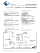
A basic block diagram of the EMIF16 asynchronous interface is shown in Figure 2-1.
Table 2-1 below lists the asynchronous signals of the EMIF16 module.
Figure 2-1 Basic Block diagram for EMIF16
Table 2-1 EMIF16 Signal Descriptions
Pin Description
EMIFD [15:0] Data I/O. Input for data reads and output for data writes.
EMIFA [23:0] External address output.
EMIFCE0
External CE0 chip select. Active-low chip select for CE space 0.
EMIFCE1
External CE1 chip select. Active-low chip select for CE space 1.
EMIFCE2
External CE2 chip select. Active-low chip select for CE space 2.
EMIFCE3
External CE3 chip select. Active-low chip select for CE space 3.
EMIFBE
[1:0] Byte enables.
EMIFWAIT [1:0] Used to insert wait states into the memory cycle.
EMIFWE
Write enable - active low during a write transfer strobe period
EMIFOE
Output enable-active low during the entire period of a read access.
EMIFRnW Read-write enable
End of Table 2-1
EMIFD [15:0]
EMIFA [23:0]
EMIFCE [3:0]
EMIFBE [1:0]
External
Memory
EMIFWE
Interface
(EMIF16)
EMIFOE
EMIFWAIT [1:0]
EMIFRnW

2.2 Memory Organization
SPRUGZ3A—May 2011 KeyStone Architecture External Memory Interface (EMIF16) User Guide 2-3
Submit Documentation Feedback
Chapter 2—Architecture
www.ti.com
2.2 Memory Organization
For information describing the device memory organization, see the device-specific
data manual.
2.3 Supported Modes
The EMIF16 module supports asynchronous interface with ASRAM, NAND and NOR.
2.4 Configuring the EMIF16 for Asynchronous Access
EMIF16 can operate in the following modes:
•WE Strobe Mode
• Select Strobe Mode
EMIF16 is clocked at CPU/6 frequency. So, for a device running at 1GHz, EMIF16 is
clocked at 166.67 MHz. All references to clock/clock cycles are in terms of EMIF16
clock cycles.
In WE Strobe mode, the byte enables EMIFBE
[1:0] can be used as write strobes for the
current active chip select space. The EMIFCEx
(x=0,1,2,3) chip select signal will remain
active throughout the duration of the asynchronous access. The main advantage of this
mode is that it allows two 8-bit devices to be connected to the same chip select. In this
mode, the bytes enables are connected to the write strobes of the two 8-bit devices. WE
strobe mode is the default mode supported on CE3. WE strobe mode is not supported
for CE0 - 2.
The Select Strobe (SS) mode is activated by setting the 'ss' bit in the Async Config
Register for the chip select under consideration. There is one Async Config Register for
each chip select. For more details on the Async Config Register, refer to Section 4.4. In
SS mode, the chip select acts as the strobe signal. So the chip select EMIFCEx
will follow
EMIFOE
for reads and EMIFWE for writes and is active only during the strobe period.
EMIFBE
[1:0] act as byte enables. SS mode is supported for all 4 chip selects.
WE strobe mode cannot be used along with Select Strobe mode. Select Strobe mode
overrides WE Strobe mode.
EMIF16 also supports an Extended Wait mode that allows the device to extend the
strobe period beyond strobe cycles during an asynchronous access. Refer to Section 3.8
for more details on Extended Wait mode.

2.5 ASRAM/NOR Flash Interface
2-4 KeyStone Architecture External Memory Interface (EMIF16) User Guide SPRUGZ3A—May 2011
Submit Documentation Feedback
Chapter 2—Architecture
www.ti.com
2.5 ASRAM/NOR Flash Interface
EMIF16 connection diagrams for 16-bit and 8-bit SRAM/NOR Flash connected to chip
select0 are shown in Figure 2-2 & Figure 2-3 respectively.
Figure 2-2 Connecting to 16-bit ASRAM (see note below)
EMIFD [15:0]
EMIFA [22:0, 23]
CE0
EMIFBE1
External
Memory
Interface
(EMIF16)
EMIFWE
EMIFOE
WAIT [1:0]
I/O[15:0]
A[N:0]
SRAM/NOR Flash
CS#
2
N+1
x 16
UB#
WE#
OE#
Vcc
LB#EMIFBE0

2.5 ASRAM/NOR Flash Interface
SPRUGZ3A—May 2011 KeyStone Architecture External Memory Interface (EMIF16) User Guide 2-5
Submit Documentation Feedback
Chapter 2—Architecture
www.ti.com
Figure 2-3 Connecting to 8-bit ASRAM
Note—EMIFA[23:22] behave as address selects. For 16-bit interface, EMIFA23
is connected to address pin A0 of the ASRAM/NOR Flash. For 8-bit interface,
EMIFA[23:22] are connected to address pins A[1:0] of the ASRAM/NOR
Flash.
2.5.1 EMIF16 Signal Description – ASRAM/NOR Flash
EMIFCE, EMIFWE, EMIFOE, EMIFBE[1:0] are the control signals that determine the
start and end of the read/write cycles. Figure 2-4 and Figure 2-5 show reads and writes
initiated by different control signals.
EMIFD [7:0]
EMIFA [21:0, 23, 22]
CE0
EMIFBE1
External
Memory
EMIFWE
Interface
(EMIF16)
EMIFOE
WAIT [1:0]
I/O [7:0]
A [N:0]
SRAM/NOR Flash
CS#
2
N+1
x 8
LB#
WE#
OE#
Vcc
X
EMIFBE0
Table 2-2 ASRAM/NOR Flash Interface Signals
EMIF16 Pin ASRAM Pin Description
EMIFD [15:0]
/EMIFD[7:0]
I/O [15:0]/
I/O[7:0]
Data I/O pins. 16/8-bit bidirectional data path for I/O.
EMIFA [23:0] A[N:0] External address outputs.
EMIFCE
[3:0] CS# Chip select for CE space. Active-low chip select for memory spaces 0
to 3.
EMIFBE
[1:0] UB#/LB# Active-low byte enables (Upper and lower). Individual bytes or
half-words can be selected.
EMIFOE
OE# Active-low output enable. Low during read access period.
EMIFWE
WE# Active-low write enable. Low during write transfer strobe period.
EMIFRnW — Read-write enable.
End of Table 2-2

2.5 ASRAM/NOR Flash Interface
2-6 KeyStone Architecture External Memory Interface (EMIF16) User Guide SPRUGZ3A—May 2011
Submit Documentation Feedback
Chapter 2—Architecture
www.ti.com
For writes, EMIFCE, EMIFWE, EMIFBE[1:0] must be active in order to initiate a write
cycle. Active status of these control signals for write is defined as EMIFCE
= LOW,
EMIFWE
= LOW and EMIFBE1 = LOW and/or EMIFBE0 = LOW. If any one of these
goes inactive, the write cycle will be terminated.
For reads, EMIFCE
= LOW, EMIFWE = HIGH, EMIFOE = LOW, EMIFBE1 = LOW
and/or EMIFBE
0 = LOW in order to successfully initiate a read cycle. Any of these
signals going inactive will terminate the read cycle.
The data input setup and hold timing must be referenced to the edge of the signal that
initiates or terminates a read or write. The truth table in Table 2-3 shows various
control signals and the resulting operating mode.
2.5.2 Programmable EMIF16 Parameters
EMIF16 module allows the user to program various parameters for all four chip selects:
• Setup - Time between the beginning of a memory cycle (chip select low, address
valid) and the activation of read or write strobe. Minimum value is 1 (0 treated
as 1).
• Strobe - Time between the activation and deactivation of the read (EMIFOE
) or
write (EMIFWE
) strobe. Minimum value is 1 (0 treated as 1).
• Hold - Time between the deactivation of the read or write strobe and the end of
the cycle (which may be either an address change or the deactivation of the chip
select signal. Minimum value is 1 (0 treated as 1).
• Turnaround - Cycles between the end of one asynchronous memory access and
the start of another asynchronous memory access minus one cycle. This delay is
not incurred between a read followed by read or a write followed by a write to
same chip select.
• Data width - Width of the asynchronous device’s data bus (8/16-bit).
The setup, strobe and hold parameters are in terms of EMIF16 clock cycles. Note that
EMIF16 is clocked at CPU/6 (166.67 MHz for 1 GHz CPU frequency). The setup,
strobe and hold values for reads can be calculated as follows (assume CPU=1 GHz).
Determine the read cycle time from device datasheet (tRC). Now tRC = r_setup +
r_strobe + r_hold. For example, if tRC = 86ns, 86 = r_setup + r_strobe + r_hold. Since
each of the 3 parameters are in terms of CPU/6, (86/6) = r_setup + r_strobe + r_hold.
This should be rounded off to the next higher integer, in this case 15. Determine from
the memory device datasheet timing diagrams what each of the 3 parameters should be.
After rounding off, always add the extra memory cycle(s) to the strobe. Similarly,
w_setup, w_strobe and w_hold can be determined.
2.5.3 EMIF16 Truth Table
Table 2-3 Control Signal Truth Table (Part 1 of 2)
EMIFCE EMIFWE EMIFOE EMIFBE[1] EMIFBE[0] I/O Operating Mode
H X X X X High-Z Deselect/Power Down
X X X H H High-Z Deselect/Power Down
L H L L L Data In on EMIFD[15:0] Read
L H L H L Data In on EMIFD[7:0] Read
L H L L H Data In on EMIFD[15:8] Read
L H H L L High-Z Output disabled

2.5 ASRAM/NOR Flash Interface
SPRUGZ3A—May 2011 KeyStone Architecture External Memory Interface (EMIF16) User Guide 2-7
Submit Documentation Feedback
Chapter 2—Architecture
www.ti.com
2.5.4 Switching Waveforms
This section describes the read and write asynchronous cycles and associated switching
waveforms for different operating modes.
2.5.4.1 Asynchronous Reads
An asynchronous read cycle proceeds as follows (see Note— 1 and 2 below):
• At the start of the setup period:
– Setup, strobe, and hold values are set according to the R_SETUP,
R_STROBE, and R_HOLD values programmed in the Async 1/2/3/4 Config
Register
– EMIFCE
becomes active (LOW) if not already active from previous
asynchronous access
– EMIFBE
1/EMIFBE0 become active (LOW)
– Address on address lines EMIFA[23:0] become valid
• At the start of the strobe period, EMIFOE
becomes active (LOW).
• At the start of the hold period:
– EMIFOE
becomes inactive (HIGH)
– Data is sampled on clock rising edge concurrent with the beginning of the
hold period (and end of strobe)
• At the end of the hold period:
– EMIFCE
goes inactive (HIGH) only if no read/write access to the chip select
space is still pending.
– EMIFBE
[1:0] become inactive.
– Address on address lines EMIFA[23:0] become invalid.
Note—1: In case an asynchronous request cannot be serviced in a single
asynchronous access cycle, multiple cycles will be needed to complete the
single read or write request. In this case, the EMIF16 enters the setup phase
directly without incurring turnaround cycles.
Note—2: If the entire read or write access has completed and there are more
requests pending, the EMIF16 enters turnaround state and waits for
programmed turnaround cycles.
L H H L H High-Z Output disabled
L H H H L High-Z Output disabled
LL X L LData Out on EMIFD[15:0]Write
L L X H L Data Out on EMIFD[7:0]
High-Z EMIFD[15:8]
Write
LL X L HData Out on EMIFD[15:8]
High-Z on EMIFD[7:0]
Write
End of Table 2-3
Table 2-3 Control Signal Truth Table (Part 2 of 2)
EMIFCE EMIFWE EMIFOE EMIFBE[1] EMIFBE[0] I/O Operating Mode

2.5 ASRAM/NOR Flash Interface
2-8 KeyStone Architecture External Memory Interface (EMIF16) User Guide SPRUGZ3A—May 2011
Submit Documentation Feedback
Chapter 2—Architecture
www.ti.com
The read cycle as described above is shown in the Figure 2-4. Refer to device datasheet
for timing characteristics.
Figure 2-4 Asynchronous Read Timing Diagram
2.5.4.2 Asynchronous Writes
An asynchronous write cycle proceeds as follows (see Note— 1, 2 below):
• At the start of the setup period:
– Setup, strobe and hold values are set according to the W_SETUP,
W_STROBE and W_HOLD values programmed in the Async 1/2/3/4 Config
Register
– EMIFCE
becomes active, if not already active from a previous access.
– EMIFBE
[1:0] become valid
– Address on address lines on EMIFA[23:0] become valid.
– Data on EMIFD[15:0] is driven
– EMIFRnW becomes active (LOW).
• At the start of the strobe period, EMIFWE
becomes active.
• At the start of the hold period, EMIFWE
becomes inactive.
• At the end of the hold period
– Address on address lines EMIFA[23:0] become invalid.
– EMIFD[15:0] becomes inactive.
– EMIFCE
becomes inactive (if no additional read/write accesses to the same
chip select space are pending).
EMIFCE
EMIFBE[1:0]
EMIFA[23:0]
Byte enables
Address
Read dataEMIFD[15:0]
EMIFOE
EMIFWE
EMIFRnW
Read setup Read strobe Read hold

2.5 ASRAM/NOR Flash Interface
SPRUGZ3A—May 2011 KeyStone Architecture External Memory Interface (EMIF16) User Guide 2-9
Submit Documentation Feedback
Chapter 2—Architecture
www.ti.com
Bus contention is addressed by having a programmable turnaround time inserted
between back-to-back accesses to the same or different CE spaces (See Section 2.5.2 for
turnaround cycles).
Note—1:
In case an asynchronous request cannot be serviced in a single
asynchronous access cycle, multiple cycles are needed to complete the single
read or write request. In this case, the EMIF16 enters the setup phase directly
without incurring turnaround cycles.
Note—2: If the entire read or write access has completed and there are more
requests pending, the EMIF16 enters turnaround state and waits for
programmed turnaround cycles.
Figure 2-5 shows a write cycle initiated as described above. Refer to the device datasheet
for timing characteristics.
Figure 2-5 Asynchronous Write Timing Diagram
2.5.5 Select Strobe Mode
The Select Strobe (SS) Mode is selected when the ‘ss’ bit in Async Wait Cycle Config
Register (AWCCR) is set to ‘1’. SS mode overrides the WE strobe mode when ‘ss’ = 1.
In SS mode, EMIFBE
[1:0] act as byte enables. However the chip select EMIFCE behaves
as the strobe and is active only during the strobe period.
EMIFCE
EMIFBE[1:0]
EMIFA[23:0]
Byte enables
Address
Write dataEMIFD[15:0 ]
EMIFOE
EMIFWE
EMIFRnW
Write setup Write strobe Write hold

2.5 ASRAM/NOR Flash Interface
2-10 KeyStone Architecture External Memory Interface (EMIF16) User Guide SPRUGZ3A—May 2011
Submit Documentation Feedback
Chapter 2—Architecture
www.ti.com
2.5.5.1 Asynchronous Reads in SS Mode
An asynchronous read cycle in SS mode proceeds as follows (see Note— 1, 2 below):
• At the start of the setup period:
– Setup, strobe and hold values are set according to the R_SETUP, R_STROBE
and R_HOLD values programmed in the Async 1/2/3/4 Config Register
– EMIFBE
[1:0] become active (LOW) as byte enables
– Address on address lines EMIFA[23:0] become valid
• At the start of the strobe period, EMIFCE
and EMIFOE become active (LOW) at
the same time.
• At the start of the hold period:
– EMIFCE
and EMIFOE become inactive (HIGH).
– Data is sampled on clock rising edge concurrent with the beginning of the
hold period (and end of strobe)
• At the end of the hold period:
– EMIFBE
[1:0] become inactive.
– Address on address lines EA[23:0] become invalid.
Note—1: In case an asynchronous request cannot be serviced in a single
asynchronous access cycle, multiple cycles will be needed to complete the
single read or write request. In this case, the EMIF16 enters the setup phase
directly without incurring turnaround cycles.
Note—2: If the entire read or write access has completed and there are more
requests pending, the EMIF16 enters turnaround state and waits for
programmed turnaround cycles.
Figure 2-6 shows the switching waveform for asynchronous reads in SS mode. Refer to
the device datasheet for device timing specifications.
/