Page is loading ...

PowerDome Series
Installation Manual

2 1040647A / July 2003
Electromagnetic Compatibility (EMC)
This is a Class A product, in a domestic environment it may cause radio interference, if this is the case
the user may be required to take remedial measures.
Manufacturer’s Declaration of Conformance
A Declaration of Conformity in accordance with the following EU standards has been made and is kept on
file at Norbain SD Ltd. Norbain House, Eskdale Road Wokingham, RG41 5TS.
The manufacturer declares that the product supplied with this document is compliant the provisions of the
EMC Directive 89/336 EEC, the Low Voltage Directive LVD 73/23, the CE Marking Directive 93/68 EEC,
and all associated amendments.
This document is intended to provide accurate information, however, the information contained herein is
subject to change without notice Vista, in keeping pace with technological advances, ia a company of
product innovation. Therefore, it is difficult to ensure that all information provided is entirely accurate and
up-to-date. Vista accepts no responsibility for any inaccuracies or omissions and specifically disclaims
any liabilities, loss, or risk, personal or otherwise which is incurred as a consequence, directly or
indirectly, of the use and/or application of any of the contents of this document.
Specifications subject to change without notice.

PowerDome Installation Manual Table of Contents
TABLE OF CONTENTS
BEFORE YOU BEGIN .......................................................................................................... 5
1 INTRODUCTION ............................................................................................................ 6
1.1 D
ESCRIPTION...................................................................................................... 6
1.2 O
PERATION REQUIREMENTS ................................................................................ 6
1.3 C
ABLE REQUIREMENTS........................................................................................ 6
1.4 P
OWER REQUIREMENTS ...................................................................................... 7
1.5 P
OWER CABLE SIZE AND LENGTH......................................................................... 7
2 HOUSING INSTALLATION............................................................................................... 8
2.1 6 INCH FLUSH-MOUNT HOUSING INSTALLATION USING THE VPD-T600 ................... 9
2.1.1 Installing the Housing ....................................................................................................10
2.2 7 INCH PENDANT-MOUNT HOUSING INSTALLATION ............................................... 14
2.2.1 Using the VPD-WM Wall Mount .................................................................................... 14
2.2.1.1 Creating a Conduit Hole................................................................................. 19
2.2.2 Using the VPD-EWM Wall-Mount Bracket ....................................................................20
2.2.2.1 Creating a Conduit Hole................................................................................. 23
2.2.3 Using the VPD-ESM Swing-Arm Mount ........................................................................ 24
3 PTZ AND DOME INSTALLATION................................................................................... 29
3.1 RS485 TERMINATION........................................................................................ 29
3.2 I
NSTALLING THE PAN/TILT ASSEMBLY ................................................................. 29
3.3 S
ETTING THE SITE ADDRESS DIP SWITCH .......................................................... 31
3.4 I
NSTALLING THE DOME ASSEMBLY ...................................................................... 32
4 PROGRAMMING AND OPERATING THE POWERDOME ..................................................... 33
APPENDIX A: MOUNTING ACCESSORIES............................................................................ 34
VPD-FCA FIXED CAMERA ADAPTER........................................................................... 34
VPD-CMA C
ORNER-MOUNT ADAPTER ....................................................................... 35
VPD-EPMA POLE-MOUNT ADAPTER.......................................................................... 35
Installing the Adapter with Bolts ................................................................................................35
Installing the Adapter with Bands..............................................................................................36
VPD-ERM R
OOF-MOUNT ADAPTER ........................................................................... 36
A
PPENDIX B: HEATER/FAN ASSEMBLY ............................................................................. 39
A
PPENDIX C: ASSIGNING DIP SWITCH VALUES ................................................................. 40
1040647A / July 2003 3

Before You Begin PowerDome Installation Manual
APPENDIX D: POWER SUPPLIES ....................................................................................... 41
VPD-PSU2 OUTDOOR POWER SUPPLY ...................................................................... 41
APPENDIX E: MIRRORED DOME HANDLING........................................................................ 43
4 1040647A / July 2003

PowerDome Installation Manual Before You Begin
BEFORE YOU BEGIN
Read these instructions before installing or operating this product.
Note: This installation should be made by a qualified service person and should conform to local codes.
This manual provides installation and operation information. To use this document, you must have the
following minimum qualifications:
A basic knowledge of CCTV systems and components
A basic knowledge of electrical wiring and low-voltage electrical hookups
Intended use
Use this product only for the purpose for which it was designed; refer to the product specification and user
documentation.
Customer Support
For assistance in installing, operating, maintaining, and troubleshooting this product, refer to this
document and any other documentation provided. If you still have questions, please contact Vista
Technical Support and Sales (+44 118 944 0123) :
Norbain House
Eskdale Road, Winnersh Triangle,
Wokingham, Berks
RG41 5TS
Note: You should be at the equipment and ready with details before calling Technical Support.
Conventions Used in this Manual
Boldface or button icons highlight command entries. The following WARNING, CAUTION, and Note
statements identify potential hazards that can occur if the equipment is handled improperly:
* WARNING:
Improper use of this equipment can cause severe bodily injury or equipment damage.
** CAUTION:
Improper use of this equipment can cause equipment damage.
Note: Notes contain important information about a product or procedure.
* This symbol indicates electrical warnings and cautions.
** This symbol indicates general warnings and cautions.
1040647A / July 2003 5

Introduction PowerDome Installation Manual
1 INTRODUCTION
This manual provides step-by-step installation instructions for all PowerDome cameras, housings and
accessories.
1.1 DESCRIPTION
A PowerDome is a variable speed PTZ (pan/tilt/zoom) dome camera used in CCTV systems for discreet
surveillance of a remote area. A PowerDome’s operational features are customized and stored within its
own on-board programmable nonvolatile memory. PowerDomes are programmed using Vista
NPX/R/KDB/J3De or VPD-KBD controller keypads.
1.2 OPERATION REQUIREMENTS
The PowerDome has three built-in receivers, two for RS485, PowerDome, and Pelco D, and one for
coaxial UTC control. The dome automatically detects the current protocol. UTC control requires a Vista
Triplex Columbus hard disk recorder and a minimum of one keyboard. See Figure 1. A minimum of one
keyboard is required for RS485 control. See Figure 2.
Note: This manual does not cover Pelco D control.
RS485 UTC
Keypad Vista Columbus digital recorder PowerDome
Figure 1. Basic application with UTC control
I/O box
Keypad (RS485 control) PowerDome
Figure 2. Basic application with RS485 control
1.3 CABLE REQUIREMENTS
For RS485 operation, PowerDomes require video, power, and data cables.
The video cable carries the video signal to the remote viewing site. If sending video via coaxial
cable, a 75 Ω coaxial cable is typically used. If sending video via twisted-pair cable, use an
unshielded, CAT5 twisted-pair cable.
6 1040647A / July 2003

PowerDome Installation Manual Introduction
The 24VAC cable powers the PowerDome and the camera. To determine cable size, refer to the
Power Cable Size and Length subsection of the Introduction.
The RS485 control cable carries commands from the keypad to the PowerDome. An RS485
compatible shielded, two-conductor, twisted-pair cable is required. Recommended cable size is 22
gauge (0.64 mm).
Note: When using the UTP interface modules Vista recommends that you use only active receivers.
For UTC control, only a video coaxial cable is required.
1.4 POWER REQUIREMENTS
CAUTION:
For optimal video performance, all PowerDomes must be powered from an isolated 24 VAC power
source—fused outputs are not adequate. Allowable voltage range is 20 to 28 V.
All domes require a 24 VAC power supply that provides isolated outputs to operate the domes’ pan/tilt
drive, camera, and heater/fan (if applicable). The total power requirement varies depending on the model
of the PowerDome.
Dome power requirements (at 24 VAC):
All domes without a heater/fan require 20 VA
7 inch domes with heater/fan require 55 VA
1.5 POWER CABLE SIZE AND LENGTH
It is important to choose the proper gauge of the cable that supplies 24 V to the PowerDome. An
inadequate gauge will cause a voltage drop resulting in improper operation.
Table 1 gives the recommended cable lengths of varying wire gauges for a PowerDome with a colour
camera. Note that the heater and fan reduces maximum cable length substantially.
Table 1. Maximum power cable lengths
Wire Gauge
All Domes
without Heater/Fan
(20 VA)
7 inch Domes
with Heater/Fan
(55 VA)
(AWG) (mm
2
) Feet Meters Feet Meters
10 2.60 1443 440 525 160
12 2.05 906 276 329 100
14 1.62 569 173 207 63
16 1.29 358 109 130 40
18 1.02 225 69 82 25
20 0.81 142 43 52 16
22 0.64 89 27 32 10
1040647A / July 2003 7

Housing Installation PowerDome Installation Manual
2 HOUSING INSTALLATION
A complete PowerDome consists of an upper housing, a
pan/tilt assembly with a built-in receiver and camera, and
an acrylic dome. See Figure 3.
Upper housing
Pan/tilt assembly
Dome
Figure 3. PowerDome components
In General: The method of installation depends on
which upper housing is being used. Installation involves
securing the upper housing, making cable connections,
mounting the pan/tilt assembly, and fastening the acrylic
dome.
The Interface Module: Make all PowerDome cable
connections (video, RS485, and 24 VAC) to an interface
module. There are two types of interface modules: one is
for coaxial video, and the other is for UTP video
transmission. When you send video via coaxial cable,
make the connections to a coaxial interface module.
When you send video via unshielded twisted-pair (UTP)
cable, make connections to a UTP interface module.
Note: Vista recommends that you use only active receivers with the UTP interface modules.
CAUTION:
For safety reasons, all mechanical components used to support the PowerDome 6 inch flush-mount and
7 inch pendant-mount assembly must be able to support a 16 kg (35 lb) load.
There are separate sections for the installation procedures for each housing style.
6 inch Flush-Mount 7 inch Pendant-Mount
Figure 4. Housing styles
These installation instructions address two
upper housing styles (See Figure 4).
To install the 6 inch flush-mount housing
see section 2.1, 6 inch Flush-Mount
Housing Installation Using the VPD-T600.
To install the 7 inch pendant-mount
housing see section 2.2, 7 inch Pendant-
Mount Housing Installation.
8 1040647A / July 2003

PowerDome Installation Manual Housing Installation
2.1 6 INCH FLUSH-MOUNT HOUSING INSTALLATION USING THE VPD-T600
Install the 6 inch flush-mount housing into ceilings with removable 600 x 600 mm or 600 x 1200 mm
ceiling panels, provided there is sufficient clearance for the unit. See Figure 5.
Top of ceiling cavity
15.88 cm (6.25 in)
minimum clearance
False ceiling
Figure 5. False ceiling clearance
The VPD-T600 is a T-bar support kit for mounting a flush-mount dome in an existing ceiling panel. The
T-bar support kit distributes the weight of the dome to the panel braces via support brackets. Each kit
comes with one ceiling ring, T-bar supports, and mounting hardware.
1040647A / July 2003 9

Housing Installation PowerDome Installation Manual
2.1.1 INSTALLING THE HOUSING
To prepare the ceiling panel see Figure 6 and perform the following.
T-bar supports T-bar bracket mounting holes
Ceiling ring
Ceiling
Use these holes to attach to panel
braces
Flathead screws (provided) Ceiling ring mounting holes
Figure 6. Installing the T-bar support kit with ceiling ring
1) Remove the appropriate ceiling panel.
2) Hold the ceiling ring in the desired location on the tile with the flat surface facing away from the
panel.
3) Use a pencil to trace the inside of the ceiling ring and to mark all five fastener hole locations.
Trace inside of
ring
Mark fastener
holes (5)
Figure 7. Using the ceiling ring as a template
10 1040647A / July 2003

PowerDome Installation Manual Housing Installation
4) Using a 5 mm drill bit, drill all five fastener holes. Ensure that all holes are drilled perpendicular to
the panel.
5) Cut a hole in the panel using the penciled tracing as a guide.
To attach the kit to the panel and install the panel, perform the following.
1) Place the long side of the T-bar support brackets flush against the inside of the panel. Align the
mounting holes with the drilled holes in the panel.
2) Place the ceiling ring on the T-bar brackets with its smooth side down and its mounting holes
aligned with the mounting holes on the brackets.
3) Using the ceiling ring mounting holes, secure the ceiling ring in place with two of the flathead screws
provided. Tighten the screws enough to draw them flush with the panel surface.
4) Replace the ceiling panel with the attached T-bar support kit in its original location.
5) Attach the T-bar support to the panel braces using the holes provided.
1040647A / July 2003 11

Housing Installation PowerDome Installation Manual
To attach the housing to the superstructure with safety cables see Figure 8 and perform the following.
Figure 8. Securing the housing to the superstructure with a safety cable.
CAUTION:
The safety cable must be able to support a 16 kg (35 lb) load.
1) Attach a metal safety cable to the ceiling’s superstructure and feed it through the mounting hole.
2) Attach the housing to the safety cable.
To make cable connections and complete the housing installation perform the following.
1) Feed the video, 24 VAC, and RS485 control cables through the ceiling to the vacated panel
location.
2) Prepare the cables as shown in Figure 9.
RS485
24 VAC
Twisted-pair video
(if used)
Strip ends of
wires
Coaxial video
(if used)
Terminate video
cable with BNC
Figure 9. Preparing cables
12 1040647A / July 2003

PowerDome Installation Manual Housing Installation
3) Make cable connections as shown in Figure 10 or Figure 11.
24 VAC
Twisted-pair video
RS485 control
signal out (if used)
RS485 control
signal in (data in)
RS485 control
signal in
RS485 control
signal out (if used)
Video
Data in (+ or A)
24 VAC
Data in (- or B)
RJ45
Video out (+)
Video out (–)
24 VAC (A)
24 VAC (B)
RJ45
Figure 10. Coaxial interface module
Figure 11. UTP interface module
4) Push the upper housing through the hole and secure it with the three provided screws.
5) Reinstall any removed ceiling panels.
6) Proceed to section 3, PTZ and Dome Installation, on page 29.
1040647A / July 2003 13

Housing Installation PowerDome Installation Manual
2.2 7 INCH PENDANT-MOUNT HOUSING INSTALLATION
Install the 7 inch pendant housing with one of the following mounts.
VPD-WM Wall Mount. See section 2.2.1, Using the VPD-WM Wall Mount.
VPD-EWM Wall Mount. See section 2.2.2, Using the VPD-EWM Wall-Mount Bracket.
VPD-ESM Swing-Arm Mount. See section 2.2.3, Using the VPD-ESM Swing-Arm Mount.
2.2.1 USING THE VPD-WM WALL MOUNT
Attach the VPD-WM Wall Mount directly to a vertical surface or mate it with a VPD-CMA Corner-Mount
Bracket, a VPD-EPMA Pole-Mount Bracket, or a VPD-ERM Roof-Mount Bracket. See Appendix A for
mounting accessory installation instructions. The following instructions explain how to install the VPD-WM
Wall Mount directly to a vertical surface.
Note: Cables will usually come out of the mounting surface and enter the unit through the rear opening in the base. If the cables are
attached externally to the mounting surface and need to enter the unit through the side, see section 2.2.1.1, Creating a Conduit
Hole.
CAUTION:
Complete all instruction steps before supplying power to the unit.
To prepare the unit and mounting surface perform the following.
1) Loosen the two cover screws enough to remove the cover (removing the screws is not necessary).
See Figure 12.
2) Remove the cover and interface module. See Figure 12.
CAUTION:
To ensure the proper operation of an attached camera, mount the adapter level.
3) Place the unit against the vertical mounting surface, ensure that it is level, and then mark the
location of the four mounting holes and the center cable-entry opening. See Figure 13.
14 1040647A / July 2003

PowerDome Installation Manual Housing Installation
Figure 12. Removing the cover and interface module
Figure 13. Marking the mounting holes and cable entry
Note: Mounting fasteners are not included.
4) Prepare the mounting holes appropriately for the type of surface (concrete, wood, etc.) and
fasteners used.
CAUTION:
The hardware and procedure used to secure the unit must enable it to support at least 16 kg (35 lb).
5) If necessary, drill a pass-through hole in the mounting surface for cable entry.
6) Pull the video, 24 VAC, and RS485 cables from inside the mounting surface through the cable-entry
hole.
To mount the unit perform the following.
1) Securely mount the unit to the wall with the appropriate fasteners. See Figure 15 and Figure 14.
Minimum of 16 kg (35 lb)
Figure 14. Mounting the unit
Figure 15. Load requirement
2) Seal all mounting holes so that no moisture can leak into the mounting surface.
To wire and mount the interface module, perform the following.
1) Prepare the cables as shown in Figure 16.
1040647A / July 2003 15

Housing Installation PowerDome Installation Manual
RS485
24 VAC
Twisted-pair video
(if used)
Strip ends of
wires
Coaxial video
(if used)
Terminate video
cable with BNC
connector
Figure 16. Preparing cables
CAUTION:
Do not connect the 24 VAC power wires to the video or RS485 connections, because it will damage the
PowerDome.
2) Wire the interface module as shown in Figure 17.
VPD-WM UTP Interface Module VPD-WM Coaxial Interface Module
Cable(s) from VPD-WM Cable(s) from VPD-WM
24 VAC Coaxial video
24 VAC
Twisted pair video out (-) 24 VAC
Twisted pair video out (+) 24 VAC
RS485 data in (- or B) RS485 data in (- or B)
RS485 data in (+ or A) RS485 data in (+ or A)
Interconnect cable Interconnect cable
2-pin Molex connector
(optional heater/fan)
2-pin Molex connector
(optional heater/fan)
Figure 17. Connections to UTP and Coaxial VPD-WM interface modules
3) Insert the interface module into the mounting slot in the VPD-WM as shown in Figure 18.
16 1040647A / July 2003

PowerDome Installation Manual Housing Installation
Figure 18. Installing the interface module into the VPD-WM
4) Attach the VPD-WM cover with the hardware provided as shown in Figure 19.
Figure 19. Attaching the VPD-WM cover
CAUTION:
Before making connections to the housing, secure the safety chain on the housing to the safety clip
inside the VPD-WM Wall Mount. Do not remove the safety cable after housing is installed.
To attach the housing safety cable to the mount safety clip see Figure 20 and perform the following.
1) Slide a section of the safety cable into the groove in the safety clip.
Note: Ensure that the taut section of the safety chain is shorter than the interconnect cable. The safety chain—not the
interconnect cable—should bear the weight of the housing.
2) Lower the housing until the safety chain is taut to ensure that it is secure.
1040647A / July 2003 17

Housing Installation PowerDome Installation Manual
Figure 20. Attaching the PowerDome pendant safety chain to the VPD-WM safety clip
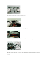
To make cable connections and attach the housing to the VPD-WM perform the following.
1) Insert the housing interconnect cable into the RJ45 jack on the VPD-WM interface module. See
Figure 21.
2) Connect the heater/fan power cable to the 2-pin Molex connector on the VPD-WM interface module.
See Figure 21.
3) Guide the flange of the housing into the collar of the VPD-WM and fasten the housing to the mount
using the provided screws. See Figure 22.
Option heater power Interconnect cable
Figure 21. Connecting the PowerDome to the
VPD-WM interface module
Figure 22. Securing the PowerDome housing to the
VPD-WM.
4) To install the optional heater/fan assembly see Appendix B.
18 1040647A / July 2003

PowerDome Installation Manual Housing Installation
2.2.1.1 CREATING A CONDUIT HOLE
To create a side conduit hole in the unit, see Figure 23 and Figure 24 and perform the following.
Template
Figure 23. Marking the pilot hole
3.5 mm (1/8 in.)
9.5 mm (3/8 in.)
13 mm (1/2 in.)
23 mm (7/8 in.)
Figure 24. Drilling a side conduit hole
1) Align the provided template with the side of the unit.
2) Mark the center of the template’s drill hole.
CAUTION:
To maintain material integrity, do not drill the conduit hole. Start with a pilot hole and enlarge it until a
knockout punch can be used to achieve the final hole size. (Hole sizes are given below.)
3) Drill a 3.5 mm (1/8 inch) pilot hole.
4) Enlarge the pilot hole to 9.5 mm (3/8 inch).
5) Use a 13 mm (1/2 inch) conduit knockout punch to enlarge the hole to 23 mm (7/8 inch).
1040647A / July 2003 19

Housing Installation PowerDome Installation Manual
2.2.2 USING THE VPD-EWM WALL-MOUNT BRACKET
Attach the VPD-EWM Wall Mount directly to a vertical surface or mate it with a VPD-CMA Corner-Mount
Bracket, a VPD-EPMA Pole-Mount Bracket, or a VPD-ERM Roof-Mount Bracket. See Appendix A for
mounting accessory installation instructions. The following instructions explain how to install the VPD-
EWM Wall Mount directly to a vertical surface.
CAUTION:
Complete all instruction steps before supplying power to the unit.
Note: Typically, cables feed out of the mounting surface and enter the wall mount unit through the rear opening in the base. If the
cables will attach externally to the mounting surface and enter the unit through the side of the unit, see 2.2.1.1 to open a side-entry
conduit hole in the unit.
Note: The factory secures the end of the safety chain with a quick tie to the dome opening as shown in Figure 25. To keep the
safety chain from slipping back into the wall mount, do not free the safety chain until you connect it to the dome.
To prepare the unit and mounting surface perform the following.
1) Remove the cable access cover from the mount. See Figure 26.
CAUTION:
To ensure the proper operation of an attached camera, mount the adapter level.
2) Place the unit against the vertical mounting surface, ensure that it is level, and then mark the
location of the four mounting holes and the outline of the cable access opening. See Figure 27.
Quick tie Safety chain fed through mount
Figure 25. Factory-attached safety chain
Figure 26. Removing the cable access cover
Figure 27. Leveling the unit and marking the mounting
holes and cable access opening onto the mounting
surface
20 1040647A / July 2003
/