Page is loading ...

7834998
Rev:
A
IMPORTANT!
INSTALLATION
INSTRUCTIONS
READ THIS
MANUAL FULLY
BEFORE UNPACKING
AND ASSEMBLING
THE ANTENNA

This document is for the following:
SHP(X)4-*** 1.2m ANTENNA
E
RE
04
Bulletin 7834998
Rev
Status
Model Version
Version
Rev
Status
Sentinel
™ 4ft(1.2m) Antennas
4ft (1.2m) with Fabric Radome
2 of 26
page
Installation Instructions
A
RE
00
Andrew Solutions
Customer Service 24 hours
U.S.A., Canada, Mexico: 1-800-255-1479
or 1-888-235-5732
U.K.: 0800 250055
Other Europe: +44 592 782 612
www.commscope.com\andrew
Visit our Web site at www.commscope.com\andrew or contact your local Andrew Solutions representative for more information.
© 2008 CommScope, Inc. All rights reserved.
Andrew Solutions is a trademark of CommScope. All trademarks identified by ® or ™ are registered trademarks or trade-
marks, respectively, of CommScope. This document is for planning purposes only and is not intended to modify or supplement
any specifications or warranties relating to Andrew Solutions products or services.
Notice: Andrew disclaims any liability or responsibility for the results of improper or unsafe installation, inspection, maintenance, or removal practices.
Aviso: Andrews no acepta ninguna obligacion ni responsabilidad como resultado de practicas incorrectas o peligrosas de instalacion, inspecci6n, mantenimiento o retire.
Avis : Andrew decline toute responsabilite pour les consequences de procedures d'installation, d'inspection, d'entretien ou de retrait incorrectes ou dangereuses.
Hinweis: Andrew lehnt jede Haftung Oder Verantwortung fur Schaden ab, die aufgrund unsachgemaBer Installation, Uberprufung, Wartung Oder Demontage auftreten.
Atencao: A Andrew abdica do direito de toda responsabilidade pelos resultados de praticas inadequadas e sem seguranca de instalacao, inspecao, manutengao ou remocao.
Awertenza: Andrew declina eventual! responsabilita denvanti dell'esecuzione di procedure di installazione, ispezione, manutenzione e smontaggio improprie o poco sicure.

This instruction describes how to assemble and adjust a SHP(X)4 antenna.
The antenna can be mounted with the mount offset to the left or to the right. Offset
left is described in this bulletin, however the images showing offset right installation
are shown at the end of this document.
Page 3 of 26
7834998
CONTENTS & INTRODUCTION
SECTION 1
INSTALLATION
INSTRUCTIONS
INTRODUCTION

Page 4 of 26
7834998
SAFETY INSTRUCTIONS
SECTION 2
INSTALLATION
INSTRUCTIONS

Page 5 of 26
7834998
SAFETY INSTRUCTIONS
SECTION 2
INSTALLATION
INSTRUCTIONS

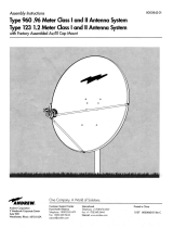
Table 1 Supplied Equipment and Tools
Page 6 of 26
7834998
EQUIPMENT AND TOOLS
SECTION 3
INSTALLATION
INSTRUCTIONS
General Table
Item
Qty
Description
Contained in Kit Part No
A
1
Reflector
B
1
Shield Set
C
1
Radome
D
1
Feed
TF-4-FREQ-19
D1
Feed Hardware Kit 6-15GHz
7613039
4
M4 x 12lg SHCS, sst, pass
4
M4 Lock Washer, sst, pass
1
Conductive Grease (tube)
D2
Feed Hardware Kit 4GHz
7776733
1
Feed Hub Adaptor Plate
4
M8X20 SCR, HEX WHSR,stl, passivated
4
M6X20,SHCS,sst,pass
1
Conductive Grease (Tube)
D3
Vertex Plate Installation Kit, 4GHz
7832527-1
2
Vertex Plate Segment
M4X10 SOKKET ,SCREW,DIN 912-ST,ST
D4
Vertex Plate Installation Kit, 6GHz
7832527-2
2
Vertex Plate Segment
4
M4X12,SCR,FH,SLOT,SST,PASS
1
LOCTITE NUTLOCK 242 1/2ML SACHET
E
1
Mount: Elevation Adjustment Assembly
7679156
F1
1
Mount: Azimuth Adjustment Clamp
7679155-LPK
F2
1
Mount: Antenna Side Bracket
7679155-LPK
G
Mount Hardware Kit
1
Conductive Grease (Tube)
2
Gloves
G1
7679221
5
M10 x 40lg Hex Hd Screw, sst, pass
5
M10 Lock Washer, sst, pass
G2
7679221
2
M10 x 100lg Hex Hd Screw, stl, galv
4
M10 Flat Washer, stl, galv
2
M10 Lock Washer, stl, galv
2
M10 Hex Nut, stl, galv
G3
7679221
1
M10 x 35lg Hex Hd Screw, stl, galv
1
M10 Lock Washer, stl, galv
2
M10 Flat Washer, stl, galv
G4
7679221
1
M10 x 140lg Eyebolt, stl, galv
2
M10 Lock Washer, stl, galv
2
M10 Flat washer, stl, galv
2
M10 Hex Nut, stl, galv
G5
7679221
1
Pipe Clamp, stl, galv
4
M10 x 130lg Hex Hd Screw, stl, galv
4
M10 Lock Washer, stl, galv
4
M10 Hex Nut, stl, galv

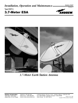
Table 1 Supplied Equipment and Tools
Page 7 of 26
7834998
EQUIPMENT AND TOOLS
SECTION 3
INSTALLATION
INSTRUCTIONS
Item
Qty
Description
Contained in Kit Part No
G6
7679221
2
M10 x 35lg Hex Hd Screw, sst, pass
2
M10 Lock Washer, sst, pass
2
M10 FlatWasher, sst, pass
G7
7679221
1
M10 x 50lg Hex Hd Screw, sst, pass
1
M10 Lock washer, sst, pass
1
M10 Flat Washer, sst, pass
H1
Shield Assembly Hardware
7614388-2
32
M6 x 12lg Hex hd Screw, sst, pass
32
M6 Lock Washer, sst, pass
32
M6 Hex Nut, sst, pass
H2
Radome Hardware
7614388-2
24
M6 X 20LG Hex hd Screw, sst, pass
24
M6 Flat Washer, sst, pass
24
M6 Lock Washer, sst, pass
J
Strut Hardware Kit
117790-3
1
Strut Bracket
1
Angle Bracket
3
M12 Washer, sst, pass
2
M12 Washer, stl, galv
3
M12 Lock Washer, sst, pass
2
M12 Lock Washer, stl, galv
2
M12 Nut, stl, galv
2
M12 x 35lg Hex Hd Screw, stl, galv
3
M12 x 30lg Hex Hd Screw,sst, pass
K
1
Strut
P99849
L
Strut Pipe Tower Clamp Hardware Kit
7637689
(refer to sheets 11 and 26 for installation configurations)
2
Clamp Bracket
1
Anchor Plate
1
M12 x 140 Hex hd Screw, stl, galv
1
M12 x160 C'sk Skt hd Screw, stl, galv
5
M12 Washer, stl, galv
7
M12 Nut, stl, galv
1
U-Bolt, M12 c/w Nuts and Washers, stl, galv
1
SCR,HCS,HEX,M16X50,STL,GALV
1
SCREW M12 X 40 CSK SKT 8.8
1
M16 Nut, stl, galv
1
WSHR,LK,SPLT,M12,STL,GALV
2
WSHR,FLT,M16,17X30X3,STL,GALV
1
WSHR,LK,SPLT,M16,STL,GALV
1
Angle Bracket

H1
A
B
H2
C
E
F1
F2
G1
G7
TO
D2
4GHz only
D3/D4
4/6GHz only
D
D1
6-15GHz only
Page 8 of 26
7834998
EQUIPMENT AND TOOLS
SECTION 3
INSTALLATION
INSTRUCTIONS

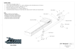
J
L
K
Page 9 of 26
7834998
EQUIPMENT AND TOOLS
SECTION 3
INSTALLATION
INSTRUCTIONS

TOOL REQUIREMENTS
Tools
Page 10 of 26
7834998
EQUIPMENT AND TOOLS
SECTION 3
INSTALLATION
INSTRUCTIONS
Tools Required
Bolt Diameter in MM
M4 M6 M10 M12
Ring and Open spanner (A/F)
10mm 17mm 19mm
Torque Wrench
Sockets (A/F)
10mm 17mm 19mm
Allen Key (A/F)
3mm 8mm

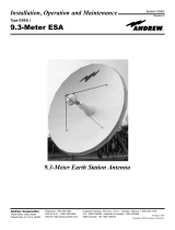
Rear Panel
A
Leave packing
struts in place
during assembly
(omitted on subsequent
views for clarity)
Page 11 of 26
7834998
UNPACKING
SECTION 4
INSTALLATION
INSTRUCTIONS
Instructions for opening crate:
1. Release wire tabs if present on the outside of the crate
2.
Remove the crate's rear panel
3. The reflector can then be hinged backwards from the bottom edge and removed from the crate
4.
Leave reflector attached to the backing struts until instructed to remove
Handle reflector
CAREFULLY at
all times

B
Loosely join ends of
shield segments with
screws, lock washers
and nuts
Reflector
mounting
holes
H1
Shield assembly sequence
LEFT-L
BOTTOM-B
RIGHT-R
B
R
L
T
Reflector
mounting slot
Drain hole
Absorber
Typical overlap
arrangement
Radome
mounting nut
Page 12 of 26
7834998
SHIELD ASSEMBLY
SECTION 5
INSTALLATION
INSTRUCTIONS
TOP-T

Insert shield in to reflector so that mounting
holes align with rim holes in reflector
Fit loosely with
lockwasher and nut in 4
opposite places as shown
Ensure highest side
of shield set is aligned
to top of antenna
Lifting eye
identifies
top of antenna
Fit bolts, lock washers and nuts to
remaining holes of reflector.
Starting
at the middle of each segment, tighten all fastenings.
Reflector
Shield
assembly
H1
4.5 Nm ±5%
Page 13 of 26
7834998
ASSEMBLY OF REFLECTOR TO SHIELD
SECTION 6
INSTALLATION
INSTRUCTIONS

Apply Loctite Nutlock to
threads prior to assembly
Tighten to 2.5Nm ± 5%
Vertex Plate Assembly 4/6 GHz only
Page 14 of 26
7834998
FEED ATTACHMENT AND ALIGNMENT
SECTION 7
INSTALLATION
INSTRUCTIONS

Apply grease to
surfaces indicated
D
Please ensure flat in
feed hub is in a
horizontal position
D1
finger tighten 4 x M4
screws, fully tighten on
final alignment
Page 15 of 26
7834998
FEED ATTACHMENT AND ALIGNMENT
SECTION 7
INSTALLATION
INSTRUCTIONS
After assembly, remove excess
grease from internal reflector surface
For 6-15GHz only
REFER TO SAFETY NOTE ON PAGE 5
Prior to feed attachment, carefully
tilt antenna upright and hold in
position.

D
Apply grease to
surfaces indicated
D1
Align timing slot in
adaptor plate with
notch in hub
mounting ring
casting
Finger tighten 6-off flanged screws
(fully tightened on final alignment)
Page 16 of 26
7834998
FEED ATTACHMENT AND ALIGNMENT
SECTION 7
INSTALLATION
INSTRUCTIONS
After assembly, remove excess
grease from internal reflector surface
For 4GHz only

Ensure radome rim tensioners
are pressed fully home.
(When fully pressed home, tensioners
are no longer loose or removable)
Unfold radome on to a
suitable surface and
assemble radome
rim tensioners at
4 places.
H2
Torque to 5.5Nm
5%
Assemble radome to shield with
screws, lock washers,
and flat washers
Pull radome tab to take up any excess
slack prior to tightening
the attachment bolts
After feed attachment, carefully tilt
antenna flat.
Page 17 of 26
7834998
RADOME ATTACHMENT
SECTION 8
INSTALLATION
INSTRUCTIONS
*Fit transition,OMT or customer interface
at this stage see separate installation instructions*

F2
G1
38Nm
5%
Assemble bracket
G2
G3
G4
Apply grease to
areas indicated
SEE SAFETY
NOTE PAGE 4
G5
E
F1
Flat washers x 2
Remove braces and discard fixings.
Carefully lay antenna on clear, flat
ground.
Do not apply excesive weight to
antenna assembly.
Page 18 of 26
7834998
MOUNT ASSEMBLY AND ATTACHMENT
SECTION 9
INSTALLATION
INSTRUCTIONS

G6
G6
G7
Apply grease to surface
indicated
38Nm
5%
38Nm
5%
38Nm
5%
SEE SAFETY
NOTE PAGE 4
Page 19 of 26
7834998
SECTION 9
INSTALLATION
INSTRUCTIONS
MOUNT ASSEMBLY AND ATTACHMENT

SLING
G5
38Nm
5%
1
1
1
2
Elevation
adjustment nut
Loosen,
do not remove.
Loosen,
do not remove.
Loosen,
do not remove.
Elevation adjustment
Loosen 3 screws (item 1).
Rotate bolt head (item 2) to adjust elevation
.
On completion tighten screws (item 1) to
38Nm ± 5%
Adjustment Range ±15°
NEVER WALK
UNDER HOISTED
LOADS
Page 20 of 26
7834998
MOUNT ADJUSTMENT
SECTION 10
INSTALLATION
INSTRUCTIONS
/