Page is loading ...

7708353
Rev:
K
IMPORTANT!
INSTALLATION
INSTRUCTIONS
READ THIS MANUAL
FULLY BEFORE
UNPACKING AND
ASSEMBLING
ANTENNA
Videos provide supplementary information - the instructions
contained within this bulletin must always be followed and take
precedence over any information contained within the video
1ft 2ft
ГК Атлант Инжиниринг – официальный представитель в РФ и СНГ
+7(495)109-02-08 [email protected] www.bbrc.ru
ГК Атлант Инжиниринг – официальный представитель в РФ и СНГ
+7(495)109-02-08 [email protected] www.bbrc.ru

2FT
1FT
This document is for the following:
VHLP(X)1/2-*** 0.3m, 0.6m ANTENNA
7708353
D
RE
03
Bulletin
Rev
Status
Model Version
Version
Rev
Status
ValuLine
™ 1ft and 2ft Antennas
1ft and 2ft (0.3m, 0.6m)
2 of 13
page
Installation Instructions
K
RE
09
Andrew Solutions
Customer Service 24 hours
U.S.A., Canada, Mexico: 1-800-255-1479
or 1-888-235-5732
U.K.: 0800 250055
Other Europe: +44 592 782 612
www.commscope.com\andrew
Visit our Web site at www.commscope.com\andrew or contact your local Andrew Solutions representative for more information.
© 2008 CommScope, Inc. All rights reserved.
Andrew Solutions is a trademark of CommScope. All trademarks identified by ® or ™ are registered trademarks or trade-
marks, respectively, of CommScope. This document is for planning purposes only and is not intended to modify or supplement
any specifications or warranties relating to Andrew Solutions products or services.
Notice: Andrew disclaims any liability or responsibility for the results of improper or unsafe installation, inspection, maintenance, or removal practices.
Aviso: Andrews no acepta ninguna obligacion ni responsabilidad como resultado de practicas incorrectas o peligrosas de instalacion, inspecci6n, mantenimiento o retire.
Avis : Andrew decline toute responsabilite pour les consequences de procedures d'installation, d'inspection, d'entretien ou de retrait incorrectes ou dangereuses.
Hinweis: Andrew lehnt jede Haftung Oder Verantwortung fur Schaden ab, die aufgrund unsachgemaBer Installation, Uberprufung, Wartung Oder Demontage auftreten.
Atencao: A Andrew abdica do direito de toda responsabilidade pelos resultados de praticas inadequadas e sem seguranca de instalacao, inspecao, manutengao ou remocao.
Awertenza: Andrew declina eventual! responsabilita denvanti dell'esecuzione di procedure di installazione, ispezione, manutenzione e smontaggio improprie o poco sicure.
ГК Атлант Инжиниринг – официальный представитель в РФ и СНГ
+7(495)109-02-08 [email protected] www.bbrc.ru
ГК Атлант Инжиниринг – официальный представитель в РФ и СНГ
+7(495)109-02-08 [email protected] www.bbrc.ru

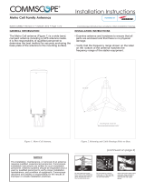
This instruction describes how to assemble a VHLP(X)1/2 antenna.
The antenna can be mounted with the mount offset to the left or to the right. Offset
left is described in this bulletin, however the images showing offset right installation
are shown at the end of this document.
INTRODUCTION
Page 3 of 13
7708353
CONTENTS & INTRODUCTION
SECTION 1
INSTALLATION
INSTRUCTIONS
ГК Атлант Инжиниринг – официальный представитель в РФ и СНГ
+7(495)109-02-08 [email protected] www.bbrc.ru
ГК Атлант Инжиниринг – официальный представитель в РФ и СНГ
+7(495)109-02-08 [email protected] www.bbrc.ru

Page 4 of 13
7708353
SAFETY INSTRUCTIONS
SECTION 2
INSTALLATION
INSTRUCTIONS
ГК Атлант Инжиниринг – официальный представитель в РФ и СНГ
+7(495)109-02-08 [email protected] www.bbrc.ru
ГК Атлант Инжиниринг – официальный представитель в РФ и СНГ
+7(495)109-02-08 [email protected] www.bbrc.ru

Page 5 of 13
7708353
SAFETY INSTRUCTIONS
SECTION 2
INSTALLATION
INSTRUCTIONS
ГК Атлант Инжиниринг – официальный представитель в РФ и СНГ
+7(495)109-02-08 [email protected] www.bbrc.ru
ГК Атлант Инжиниринг – официальный представитель в РФ и СНГ
+7(495)109-02-08 [email protected] www.bbrc.ru

Page 6 of 13
7708353
SAFETY INSTRUCTIONS
SECTION 2
INSTALLATION
INSTRUCTIONS
ГК Атлант Инжиниринг – официальный представитель в РФ и СНГ
+7(495)109-02-08 [email protected] www.bbrc.ru
ГК Атлант Инжиниринг – официальный представитель в РФ и СНГ
+7(495)109-02-08 [email protected] www.bbrc.ru

Table 1 Supplied Equipment and Tools
Page 7 of 13
7708353
EQUIPMENT AND TOOLS
SECTION 3
INSTALLATION
INSTRUCTIONS
Refer to Pg 9 for pictorial reference to contents list for Item B Mount Kit
TOOL REQUIREMENTS
Tools
* If ordered with Antenna.
Item
Qty
Description
Contained in Kit Part No
A
1
Reflector Assembly
B
1
Mount Kit
C
1
Customer Interface
*
Tools Required
Thread Diameter
in MM
M10
Ring and Open Spanner (A/F)
17mm
Torque Wrench
Sockets (A/F)
17mm
ГК Атлант Инжиниринг – официальный представитель в РФ и СНГ
+7(495)109-02-08 [email protected] www.bbrc.ru
ГК Атлант Инжиниринг – официальный представитель в РФ и СНГ
+7(495)109-02-08 [email protected] www.bbrc.ru

B
NOTE:UPPACKING BOX SEE PAGE 9 FOR DETAIL
MOUNT KITS.
A
Equipment
7708353
Page 8 of 13
EQUIPMENT AND TOOLS
SECTION 3
INSTALLATION
INSTRUCTIONS
1FT SHOWN FOR REFERENCE
B
C
CUSTOMER INTERFACE.
(IF ORDERED WITH ANTENNA)
ГК Атлант Инжиниринг – официальный представитель в РФ и СНГ
+7(495)109-02-08 [email protected] www.bbrc.ru
ГК Атлант Инжиниринг – официальный представитель в РФ и СНГ
+7(495)109-02-08 [email protected] www.bbrc.ru

B4-1
B4-2
B4-3
B4-4
B4-5
B4-6
B4-7
B4-8
B4-9
B4-10
B4-11
B4-12
B3
B2
B4
or
Page 9 of 13
7708353
UNPACKING
SECTION 4
INSTALLATION
INSTRUCTIONS
Unpacking Mount Kit
B
B1
B4-2
Kit Variants*:
* No functional change
between kit variants.
Sub
ASSY
Lower Level
Qty
Description
Contained in Kit Part
No
B
Mount Kit
7705250
B1
1
Elevation Adjuster Assembly
7705239
B2
1
Pipe clamp
7676242
B3
1
V Clamp Bracket
7676245
B4
1
Mount Hardware Kit
7724926
B4-1
1
Azimuth Adjuster Assembly
B4-2
1
Adjuster Boss
B4-3
1
Nut,Hex Thin,M10,sst,Pass
B4-4
6
Nut,Hex,DIN 934,M10,sst,Pass
B4-5
7
Wshr,LK,Split,M10,sst,Pass
B4-6
9
Wshr,FLT,M10,10.5X20X2,sst,Pass
B4-7
1
Scr,HCS,Hex,M10X20,sst,Pass
B4-8
1
Scr,HCS,Hex,M10X30,sst,Pass
B4-9
1
Scr,HCS,Hex,M10X45,sst,Pass
B4-10
2
Scr,HCS,Hex,M10X90,sst,Pass
B4-11
2
Scr,HCS,Hex,M10X150,sst,Pass
1
Conductive Grease (Tube)
2
Gloves
B4-12
1
SPACER
ГК Атлант Инжиниринг – официальный представитель в РФ и СНГ
+7(495)109-02-08 [email protected] www.bbrc.ru
ГК Атлант Инжиниринг – официальный представитель в РФ и СНГ
+7(495)109-02-08 [email protected] www.bbrc.ru

M10 x 30
Torque to 38Nm ± 5%
M10 x 45
Torque to 38Nm ± 5%
M10 x 20
Torque to 38Nm ± 5%
Assemble antenna mount to
antenna assembly as shown.
Note:For installation of interface see separate instructions.
Apply grease to surfaces shown,
use gloves provided.
50-120 mm
Pole to be structural
engineer approved
rigid structural support
Secure mount to pole as shown.
Tighten 2x nut
to torque of 38Nm ± 5%`
M10 x 150
Pre-assemble antenna
mount as shown. Unless
a torque is specified fit
screws finger tight.
Tighten nut to torque
of 38Nm ± 5%
M10 x 90
Torque to 38Nm ± 5%
Manually adjust
azimuth
to center of slot
BEFORE torquing
Apply grease to all threads
prior to assembly, use gloves
provided.
INSTALLATION
INSTRUCTIONS
SECTION 5
MOUNT ATTACHMENT AND ALIGNMENT
7708353
Page 10 of 13
Assemble Mount to antenna at ground level
prior to attachment to tower
Pre-assembly of Mount
1
NEVER WALK
UNDER HOISTED
LOADS
2
Mounting of Antenna
ГК Атлант Инжиниринг – официальный представитель в РФ и СНГ
+7(495)109-02-08 [email protected] www.bbrc.ru
ГК Атлант Инжиниринг – официальный представитель в РФ и СНГ
+7(495)109-02-08 [email protected] www.bbrc.ru

Do NOT exceed 4Nm
5%
Adjust azimuth by rotating 2x nuts
A
B
After screws A and B have been
tightened,Torque nuts to 10Nm ± 5%
Ensure screws are torqued to 38Nm ± 5%
Then loosen off 1/4 turn to allow adjustment
Adjust elevation by rotating Elevation
adjuster bolt (part of elevation
adjustment assembly)
IMPORTANT
Do
NOT
tighten/loosen these nuts
On completion torque screws
to 38Nm ± 5%
Page 11 of 13
7708353
MOUNT ATTACHMENT AND ALIGNMENT
SECTION 5
INSTALLATION
INSTRUCTIONS
Elevation Adjustment
3
Azimuth Adjustment
4
Ensure screws are torqued to 38Nm ± 5%
Then loosen off 1/4 turn to allow adjustment
On completion torque screws to 38Nm ±
5%. Tighten screw A first then screw B
Do NOT exceed 10Nm
5%
ГК Атлант Инжиниринг – официальный представитель в РФ и СНГ
+7(495)109-02-08 [email protected] www.bbrc.ru
ГК Атлант Инжиниринг – официальный представитель в РФ и СНГ
+7(495)109-02-08 [email protected] www.bbrc.ru

Antenna Offset Left
Antenna Offset Right
1FT SHOWN FOR REFERENCE
Page 12 of 13
7708353
MOUNT ATTACHMENT AND ALIGNMENT
SECTION 5
INSTALLATION
INSTRUCTIONS
Pole to be structural engineer
approved rigid structural support
For installation of interface
see separate instructions.
Fit radio per instructions.
For installation of interface
see separate instructions.
Fit radio per instructions.
ГК Атлант Инжиниринг – официальный представитель в РФ и СНГ
+7(495)109-02-08 [email protected] www.bbrc.ru
ГК Атлант Инжиниринг – официальный представитель в РФ и СНГ
+7(495)109-02-08 [email protected] www.bbrc.ru

Page 13 of 13
7708353
SECTION 6
INSTALLATION
INSTRUCTIONS
6 General Information
6.1 General maintenance
The antenna is designed such that minimal maintenance is required. Other
than strong wind conditions the unit is not subject to abnormal forces and
regular inspection and maintenance should ensure trouble free operation.
6.2 Cleaning of Antenna
If subsequent cleaning of the antenna is required solvent based solutions
must not be used.
GENERAL INFORMATION
ГК Атлант Инжиниринг – официальный представитель в РФ и СНГ
+7(495)109-02-08 [email protected] www.bbrc.ru
ГК Атлант Инжиниринг – официальный представитель в РФ и СНГ
+7(495)109-02-08 [email protected] www.bbrc.ru
/