Page is loading ...

704 North Clark Street
Albion
MI 49224 USA
Phone +1 517 629 5990
Fax +1 517 629 5990
www.sepatriot.com
Patriot Antenna Systems
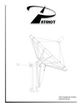
Assembly Manual for the
1.0m Back Pack Antenna
System
1.0 meter Back Pack Antenna
Revision 002

CONTENTS
INTRODUCTION........................................................................................................................................ 2
MECHANICAL SYSTEM DESCRIPTION.............................................................................................. 3
BACK PACK ............................................................................................................................................. 3
AZ-EL ANTENNA BASE ......................................................................................................................... 3
1.0M REFLECTOR.................................................................................................................................... 3
.................................................................................................................................................................... 3
REFLECTOR ASSEMBLY........................................................................................................................ 6
FEED ASSEMBLY .................................................................................................................................... 11
INTRODUCTION
This is a deployable antenna system that comes carefully packed in a portable back
pack case
. It is a precision instrument that will provide many years of reliable service if
assembled and handled with proper care.
Become familiar with these instructions before attempting to work with this antenna system.
Completely unpack all the components and identify each one to know it’s function and
purpose.
2

MECHANICAL SYSTEM DESCRIPTION
BACK PACK
The antenna is provided in a carrying case measuring approximately 15 x 25 x 12”,
and weighs approximately 65 pounds. The back pack case has the added features of
having roller wheels and an extendable handle for easy handling where applicable.
Back Pack shoulder straps are also provided for carrying the case on one’s back.
AZ-EL ANTENNA BASE
The Antenna Base is comprised of three detachable legs that have adjustable feet for
rough leveling of the assembly, and an Azimuth bearing assembly that the reflector
assembles to using a simple “insert and turn” design. The elevation adjustment is
accomplished using a turnbuckle that can be rough adjusted in slotted ribs on the
back of the reflector, then fine adjusted by turning the body of the threaded
turnbuckle. Azimuth adjustment is accomplished by using a turn knob that moves
the antenna in a controlled means in the azimuth plane until the RF signal is peaked.
A locking handle mechanism then locks it to the desired location.
1.0M REFLECTOR
The Reflector is in six pieces that interlock using dowels, and latches to secure the
pieces together into an accurate assembly. Be sure to follow the assembly procedure
to properly interlock the pieces. The Feed system is precisely held in place using
side struts with ball snaps to the main feed tube. The Feed assembly detaches easily
using one ¼ turn knob.
3

4

MOUNT ASSEMBLY
The pack has two divided compartments. The topmost compartment has an access
flap that is easily opened with its’ perimeter zipper. Open this flap and you will find
the Mount Assembly parts needed for this stage of the assembly.
1. Slide the Feet assemblies into each of the 3 Leg assemblies as shown. The flatted
side of the pin faces the locking cam. Simply turn the cam downward to lock the
pin at the desired height.
2. Insert the Leg assemblies onto the bottom side of the AzEl assembly as shown,
by aligning the dowels and tightening the threaded fasteners.
3. Roughly level the Mount Assembly using the level bubble as a reference by re-
adjusting the Feet assemblies per step 1.
5

REFLECTOR ASSEMBLY
Two of the reflector panels are in the topmost compartment, and the remaining four
as well as the feed support parts are in the bottom compartment which can be
accessed with the perimeter zipper around the middle of the case. Remove them
taking note how they were packed so they can be repacked accordingly. You will
need the bottom-most panel to begin with.
1. Starting with panel B2, guide the mounting lugs into the receiving brackets of the
Mount assembly taking care to align the flatted sides of the pins with the flatted
sides of the receiver brackets. Then with the indicator line of the knob aligned
pointing to the Elevation Turnbuckle, pivot the panel assembly engaging the
turnbuckle into the knob pin. When fully engaged turn the knob approximately
¼ turn CCW to lock. The panel assembly is now fully locked to the mount
assembly.
2. Adjust the Elevation to approximately 30 degrees for the installation of the
remaining five panels. (Elevation scale is on back of panel B2 near Turnbuckle)
6

3. Install panel T2 by simply guiding it into position as shown onto the alignment
dowels. The panel will stay in place. The seam between the panels should look
flush.
7

4. Install panel T1 and B3 using the same procedure as in step 3.
8

5. Install panel B1 and B3 using the same procedure as in step 3. Panels B1 and B3
will need to be held slightly back and aligned simultaneously with their
respective upper panel and it’s alignment dowel.
9

After making sure all seams look flush fasten the two latches on the back of the dish, then fasten
the six remaining perimeter latches.
10

FEED ASSEMBLY
1. With all latches securely latched readjust Elevation Angle to facilitate attachment
of the Feed Assembly parts. (Appox. 45deg)
2. Insert the Feed Tube assembly into the receiver at the bottom of panel B2. It
must be held at the approximate angle shown. Then once it is fully inserted,
rotate upwards to be able to attach the side struts.
11

3. Attach each side strut. Snap on to side panels first then snap to corresponding
ball snap on the Feed Tube assembly.
Assembly is now complete.
Antenna system can acquire satellite once RF connections are complete.
12
/