Andrew 123 1.2 Meter Class I Assembly Instructions Manual
- Category
- Television antennas
- Type
- Assembly Instructions Manual
This manual is also suitable for

Assembly
Instructions
Type
960
.96
Meter
Class
I
and
II
Antenna
System
Type
123
1.2
Meter
Class
I
and
II
Antenna
System
with
Factory
Assembled
Az/EI
Cap
Mount
,,...
Andrew Corporation
3 Westbrook Corporate Center
Suite
900
Westchester, Illinois
60154
USA
One
Company
. A World
of
Solution
s.
Customer Support Center
From
North America
Telep
h
one:
1-
800
-255-
14
79
Fax 1
-800
-
349-5444
sa
t
com@a
ndrew.com
International
Telephone:
+1-
708
-873-2307
Fax:
+1-
708-349-5444
Internet: www.andrew.com
8000842-01
Printed
in
China
11/07 8000842-
01
Rev
C


MANUAL
REVISION
HISTORY
11/07
WARRANTY
REVISION
5075515
Reve
ANDREW
CORPORATION
VERY
SMAll
APERTURE
TERMINAL
(VSAT)
PRODuas
TWELVE
(12)
MONTH
LIMITED
WARRANTY
Seller
warrants
that
all
ANDR
EW
manufactured
VSAT
products
are
transferred
rightfully
and
with
good
title
;
that
they
are
free
from
any
lawful
securi
ty
interest
or
other
lien
or
encumbrance
unknown
to
Buyer.
Seller
also
warrants
that
for
a
period
of
twelve
(12)
months
from
the
date
of
shipment
from
Seller's
factory
,
all
its
VSA
T
products
shall
be
free
from
defects
in
material
and
workmanship
which
arise
under
proper
and
normal
use
and
service.
Buyer's
exclusive
remedy
hereunder
is
limited
to
Seller
's
correction
(either
at
its
plant
or
at
such
other
place
as
may
be
agreed
upon
between
Seller
and
Buyer)
of
any
such
defects
by
repair
or
replacement
at
no
cost
to
Buyer,
except
for
the
costs
of
any
transportation
in
connection
with
the
return
of
the
defective
VSAT
products
to
be
replaced
or
repaired
,
and
the
costs
to
remove
and/or
reinstall
the
products,
which
sha
ll
be
borne
by
Buyer.
The
l
imit
ed
warranty
period
shall
not
be
extended
beyond
its
original
term
with
respect
to
any
part
or
parts
repaired
or
r
eplaced
by
sel
ler
hereunder.
This
w
arranty
shall
not
apply
to
VSAT
products
which
(i)
ha
ve
been
repaired
or
altered
in
an
y way
so
as
to
affect
stabi
l
ity
or
durability
,
(ii)
ha
ve
been
subject
to
misuse
,
negligence
or
accident
,
(iii)
ha
ve
been
damaged
by
severe
weather
conditions
such
as
ex
cessi
ve wi
nd
, i
ce
,
storms
,
lightning
,
or
other
na
tural
occurrences
beyond
Seller's
control
;
(i
v)
have
presented
damages,
defects
or
nonconformances
caused
by
improper
shipping
,
handling
or
storage
,
and
(v)
have
not
been
installed
,
operated
or
maintained
in
accordance
with
Seller
's
instructions.
Buyer
sha
ll
present
any
claims
along
with
the
defective
VSAT
product(s)
to
Sel
ler
imm
ed
iat
ely
upon
failure
Non-compliance
with
any
part
of
this
warranty
procedure
may
invalidate
this
warranty
in
whole
or
in
part
.
SE
LLER
MAKES
NO
WARRANTY
,
EXPRESS
OR
IMP
LIED
,
OTH
ER
THAN
AS
SPECIF
I
CA
LL
Y ST
AT
ED
ABOVE.
EXPRESSLY
EXCLUDED
ARE
ANY
IMP
LIED
WARRANT
IE
S
OF
MERC
H
ANTAB
ILIT
Y
OR
FITNESS
FOR
A
PARTICULAR
PURPOSE.
THE
FOREGOING
SHAL
L
CONSTITUTE
A
LL
OF
SEL
LE
R'S
LIABI
LI
TY
(EXCEPT
AS
TO
PATEN
T IN
FRI
NG
E
MENT)
WIT
H
RESPEC
T
TO
T
HE
VSAT
PRODUCTS
.
IN
NO
E
VENT
SHALL
SEllER
BE
LIABLE
FOR
ANY
LOSS
OF
PROFITS
OR
RE
V
ENUE
,
LOSS
OF
USE
, IN
TERRUPTI
ON
OF
BUSINESS
,
OR
INDIRECT,
SPECIAL,
CONSE
QUENT
I
AL
OR
INCIDENTAL
DAMAGES
OF
ANY
KIND
AS
A
RESUL
T OF
THE
USE
OF
TH
E
PRODUCTS
MANUFACTURED
BY
SELL
ER, WH
ETHE
R
USED
IN
ACCORDANCE
W
ITH
THE
INSTRUCTIONS
OR
NOT.
UNDER
NO
CIRCUMSTANCES
SHALL
SE
LLER
'S
LIABILITY
TO
BUYER
EXCEED
THE
AC
TU
AL
SALES
PRICE
OF
THE
VSAT
PRODUCTS
HEREUNDER.
In
some
jurisdictions,
Bu
y
er
ma
y
ha
ve
other
rights
under
certain
statutes
that
ma
y
imply
non-e
x
cludable
w
arranties.
No
representative
is
auth
o
rized
to
as
sume
for
Seller
an
y
other
liability
in
connection
w
ith
the
V
SAT
pr
o
ducts
.
DO
NOT
DISCARD
CONTENTS
The
product
in
this packaging was placed
in
the
market after August
13
,
2005
.
Its
components
must
not
be
discarded with
normal municipal or household waste. -
Contact your
local waste disposal agency for recovery, recycling, or disposal instructions.

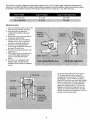
WARNINGS
LAW:
Installation and installer
must
meet local codes and ordinances regarding safety! Installation
of
this
product should be performed only
by
a professional installer and
is
not recommended for consumer Do-it-Yourself installations.
DANGER:
WATCH
FOR
WIRES!
Installation of
this
product near power lines
is
extremely dangerous and
must
never be attempted. Installa-
tion of
this
product near power lines can result in death or serious injury!
For
your own safety, you
must
follow these important safety rules.
Failure
to follow
these
rules
could result
in
death or serious injury
1.
Perform
as
many functions
as
possible on the ground
2. Watch out for overhead power
lines. Check the distance
to
the power lines before starting installation. Stay at least 6 meters (20
feet)
away
from all power lines.
3. Do not install antenna or mast assembly on a
windy
day.
4.
If you start
to
drop antenna or mast assembly, move
away
from it and let it fall.
S.
If any part of the antenna
or
mast assembly comes in contact with a power line, call your local power company. DO
NOT
TRY
TO
REMOVE
IT
YOURSELF!
They will remove it safely.
6. Make
sure
that the
mast
assembly
is
properly grounded.
WARNING:
Assembling dish antennas on
windy
days
is
extremely dangerous and
must
never be attempted.
Due
to the surface area
of
the
reflector,
even
slight winds create strong forces.
For
example, this antenna facing a wind of 32
km/h
(20
mph)
can undergo forces of
269 N
(60
Ib)
.
BE
PREPARED
TO
SAFELY
HANDLE
THESE
FORCES
AT
UNEXPECTED
MOMENTS.
AmMPTlNG
TO
ASSEMBLE,
MOVE
OR
MOUNT
A
DISH
ON
WINDY
DAYS
COULD
RESULT
IN
DEATH
OR
SERIOUS
INJURY.
ANDREW
is
not responsible or liable for damage or
injury
resulting from antenna installations.
WARNING:
Antennas improperly installed or installed to an inadequate structure are very susceptible to wind damage.
This
damage
can be very serious or even
life threatening.
The
owner and installer
assumes
full responsibility that the installation
is
structurally sound to
support
all loads (weight, wind and
ice)
and properly sealed against leaks. ANDREW will not accept liability for any damage caused
by
a
PRE
INSTALLATION
CONSIDERATIONS
TOOLS
REQUIRED:
Compass
Clinometer
3/8
" Drive Ratchet Wrench
13
mm
Deep Socket
(3/8"
Drive)
#1
or
#2
Phillips Screwdriver
13
mm
Combination Wrench
ADDmONAL
INSTALLATION
MATERIALS
(Not
Included
with
Antenna)
Installation Mount (Ground
Pole
, King
Post,
Wall
Mount or Roof Mount)
10
mm
Nut
Driver
10
mm
Socket
(3/8
" Drive)
1
0
mm
Combination Wrench
Grounding
Rod,
Clamp & Grounding Block -
As
required by National Electric Code or local codes.
Torque Wrench
9" Magnetic
Level
(2)
17
mm
Open
End
Wrenches
Ground
Wire
- #10 solid copper or
#8
aluminum
as
required by National Electric Code or local codes (length
as
required).
RG-6
Coaxial Cables from antenna to indoor
units
.
Concrete:
See
"Ground
Pole"
section for quantity
MlO
or #3 Rebar:
See
"Ground Pole" section for quantity. Deformed
steel
per ASTM A615, Grade
40
or
60
.
SITE
SELECTION
The
first and
most
important consideration when choosing a prospective antenna
site
is
whether or not the area can provide an accept-
able "look angle" at the satelli
tes
. A
site
with a clear, unobstructed view is preferred. Also consider obstruction that may occur
in
the
future
such
as
the growth
of
trees
.
Your
antenna
site
must
be selected
in
advance
so
that you will be able to receive
the
strongest signal available.
To
avoid obstructions,
etc
.,
conduct an on-
site
survey with a portable antenna.
The
satellite antenna can be installed on a ground pole,
wall/roof
mount, or non-penetrating roof mount with 2-7/8" or
3"
outside diameter
mast.
The
chosen mount type should be assembled and
in
place before installing the antenna.
Refer
to instructions packed with mount for
its
proper installation.
The
mast pipe
must
be vertical and
plumb
to
insure ease of alignment.
As with any other type
of
construction, a local building permit may be required before installi
ng
an antenna.
It
is
the property owner's
responsibility
to
obtain any and all permits.
Before any digging
is
done, information regarding the possibility of underground telephone lines, power lines, storm drains, etc., in the
excavation area
should be obtained from the appropriate agency.
Because
soils vary
widely
in
composition and load capacity, consult a local professional engineer to determine the appropriate foundation
design and
installation procedure. A suggested foundation design with conditions noted
is
included
in
this
manual for reference purposes
only.
2

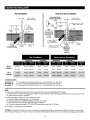
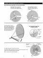
GROUND
POLE
INSTALLATION
Pier
Foundations
Deep
Frost
Line
Foundations
Ground
Pole
Must
Be
- -
7.3
cm
or
7.6
cm
(2
.88"
or
3.00"
O.D.)
Vertical
in
All
Directions
II
at
Top
- -
7.3
cm
or
7.6
cm
(2.88"
or
3.00" O.D.)
t
91.4
c~
max.
#3
rebar
x diameter
(36")
of
pier. Insert through
hole in
tube
and center.
~
'obbl. t
91.4
ct
max.
Level
(36
")
NOTE:
127
cm
(50
") may
be increased
to
frost
line. Concrete and
length
of
rebar will
increase
accordingly.
182.9
cm
#3
rebar x
.46
m
(18")
Insert through
hole in tube and center.
#3
rebar x
.6
m
(24
")
at
60
'
apart
(See
note)
Bottom
View
Pier
Foundations
Deep
Frost
Line
Foundations
,
EXPOSURE
B
EXPOSUREC
EXPOSURE
B
DIM
D
CONC
VOL
DIM
D
CONC
VOL
DIM
D
CONC
VOL
em
(in)
m
3
IfP)
em
(in)
m
3
liP)
em
lin) m
3
(ft3)
96
em
161
(100)
25
(10)
0.
05
(1.8)
38
(15)
0.12
(4.1)
18
(7)
0.03
(1.1)
Antenna
201
(125)
36
(14)
0.10
(3.7)
51
(20)
0.21
(7.4)
23
(9)
0.05
(1.9)
1.2
m
161
(100)
30
(12)
0.07
'
(:2
,
5)
.
46(18)'
OOl
~
16.0)
.
~(8)
",
0.04 (l.4)
Antenna
20i (l25)"
6jO{1O
.
5
~
~
0.Q?{i
2)
'0
61(24) 30
(12)
,
"'"
...
~
POLE
SPECIFICATIONS:
Ground
Pole
"/I:'
Ground
Pole
"B"
Ground
Pole
"C"
NOTE:
2-1/2
Schedule
40
Steel
ASTM
A53
Pipe
(73
mm
x 5
mm
WaI1/2
.
BB"
00
x .203"
Wall)
3.0"
00
x 9
Gauge
(.
14B"
Wall)
Steel
ASTM
A501
Pipe
(76
mm
00
x 3.B
mm
Wall)
2-1/2
Schedule
BO
Steel
ASTM
A53
Pipe
(73
mm
x 7
mm
Wall/2.BB"
00
x .276"
Wall)
EXPOSURE
C
DIM
D
CONC
VOL
em
(in)
m
3
liP)
25(10)
0.06
(22)
36
(14)
0.13
(4.6)
",-~
9.11
(3.8)
1.
Poles
are not supplied (purchase locally to above specifications) and
must
be field drilled
5/8"
diameter
A,
B
or
C
A, B
or
C
A,S
orC
for
MlO
#3 rebar, 5.5
mm
for self tapping grounding screw and (.218") for 1/4-20 self tapping grounding screw.
Poles
and screws
must
be galvanized or painted for protection.
2.
Pole
and foundation design based on the following criteria:
.
c.
Uniform building code Exposure B or C wind loading.
b. Vertical soil pressure of 13790
kPa
(2000
pounds per square foot).
c.
Lateral soil pressure of 2758
kPa
(400
pounds per square foot).
d. Concrete compressive strength
of
17.2
MPa
(2500
pounds per square inch)
in
28
days.
3.
See
page 6 for grounding recommendations.
CAUTION:
The
foundation design shown does not represent an appropriate design for any specific locality. Soil conditions vary and may
not meet design criteria given
in
Note
2.
Consult a local professional engineer
to
determine your soil conditions and appropriate foundation.
3

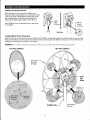
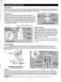
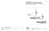
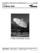
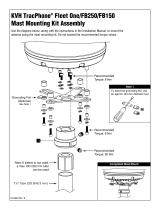
The
Az/EI
mount
is
factory configured to achieve elevation angles from 8° to
54°
.
For
higher angles, the elevation adjustment screw
setting
must
be modified.
(See
table for elevation ranges). Before proceeding with antenna installation, determine the elevation angle for
the
site
(refer to main installation instructions). If the elevation setting for the
site
is
greater than -
52
°, follow
these
steps:
Antenna
Model
Range
As
Shipped
Range
At
High
Angle
Setting
1.2
m
Type
123
-~-
96 cm
Jype
960
Adjushnent
procedure:
Loosen
two
elevation clamp
nuts
(in
curved
slots),
and loosen elevation pivot bolts
2 Swing the housing up against the
underside of the
elevation adjustment
screw head
3
Set
the
az/el
mount on the side closer to
the
elevation adjustment bolt
4
Loosen
the bottom nut on the elevation
adjustment screw.
(Use
two open-end
wrenches to
release the double
nuts)
5
Run
the top nut up tight against the
az/el
housing and elevation screw head,
then
back
off
nut half a turn
6
Run
bottom nut along the elevation screw
against top nut
7
While
holding the top nut
in
place with a
wrench
firmly tighten the bottom nut
against it to
lock
them
both
in
that
position.
S
The
az/el
is
now configured for high
elevation angles. Proceed with the
installation
as
instructed
in
the installation
manual.
U
Bracket
Hex
Nuf
Swivel
Nut
8°
to
54·
8·
to
54°
Elevation
Pivot
Bolts
-
(2
Places)
(JD-
...........
-++-~
~~
...
~:
'
CJOmp
BOlts
-(Carriage
Bolt
.
andHexNu~
14
Places)
42°
to
85°
34·
to
85°
Clamp
Nut
(2
Places)
Note
new
position
of
top
c'
and
bottom
nut.
~
~
o
High
Elevation
Angle
Setting
Loosen
(4)
carriage bolts and
nuts
securing the
"U"
bracket to the top bracket.
Loosen
(4)
carriage bolts and
nuts
securing
"U"
Bracket to
(2)
half clamps.
Loosen
swivel nut and hex nut.
Install AZ/EL cap mount onto ground pole. Equally
tighten
(4)
clamp bolts
so
that cap
is
held station-
ary
on ground pole, but can be swiveled with
slight pressure (approximately
2.7
N-m
(2
ft-Ib)
.
Retighten and torque
(4)
carriage bolts and
nuts
securing
"U"
bracket to half clamps to
24.4
Nm
(18
ft-Ib)
.
Leave
loose
(4)
carriage bolts, swivel nut
and hex
nuts,
for fine tune option.

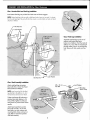
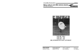
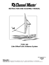
ASSEMBLY
AND
INSTALLATION
Installing
Az/EI
Cap
Mount
Onta
Pole
Be
fore installing
az/el
cap onto pole, installation mount
should be
in
place. loosen
(4)
hex
nuts
on pipe clamp. Insta
ll
az/el
cap onto pole. Equally tighten
(4)
clamp bolts
so
that
cap
is
held
sta
tionary on pole, but can be swiveled wi
th
slight pressure. Tighten approximately 2.7 N-m
(2
ft-Ib
).
Insert
(2)
MS
set
screws into threaded inserts
in
pipe clamp.
Do not tighten.
Assembling
Reflector
Onto
Az/EI
Cap
Mount
Clamp
Bolts
(4
Places)
Back
View
MS
Set
Screws
(2
Places)
Install four MS x
60
mm
plow
bolts into holes
in
reflector face.
lift
reflector and insert exposed portion of bolt into holes in
az/el
mounting
flange. Secure reflector to
az/el
mount with 4 lock washers and hex
nuts
onto plow bolts. Tighten and torque to
15
N-m
(11
ft-
Ib).
Press
fit
hole plugs
in
remaining four unused holes of the reflector.
IMPORTANT:
Note
orien
t
ation
of
feed
leg
mounting
holes
in
reflector
rim.
Top
of r
eflector
does NOT
have
fe
ed
leg
mounting
ho
le.
Front
View
of
Reflector
_.
,- '
,
.
,
-'
. . --
..
MS
:
60mm
C
PIOW
.•
BOitS
.
(4
Places)
-----.
\0
~~
ug
,
(4
Places)
MS
x
60
mm
Plow Bolts
(4
Places)
5
Rear
View
of
Reflector
~~r--
-Az/EI
Installation
Pole
lock
Washer
(4
Places)
Cap
Mount

ASSEMBLY
AND
INSTALLATION
for
Class
I
Antennas
Class
I
Junction
Block
and
Feed
Leg
Installation
Insert bottom feed leg
in
to junction block and twist until lance engages.
NOTE:
Bottom
feed
leg
is
the
one
with
a
slight
bend and a
lance
on
one
end.
It
is
shorter
than
the
side
feed
legs.
The
end
with
the
lance
inserts
in
iunction
block
and end
with
bend
attaches
to
reflector.
Class
I
Feed
Assembly
Installation
Attach side feed legs to junction
block with
M6
x 16
mm
Hex Head
Bolt and
M6
Lock
Washer.
NOTE:
Long
formed
end of
sid
e feed
leg
attaches
to
the
re
flector
rim,
sh
ort
formed
end to
side
of
iunction
block.
Tighten and torque all hardware to
junction
block and reflector to 5.4
N-m
(4
ft-Ib).
Tighten two
M4
pan
head screws
in
junction block socket
equally.
Attach feed assembly to junction
block with two
M6
x 16
mm
hex
head
bolts, two lock washers and
mounting
block clamp
as
shown on
right.
Refer
to
instructions packed
with feed
assembly.
M6
Hex
Nut
~
---
Lock
Washer
6
Class
I
Feed
Legs
Installation
Assemble side feed legs
to
side rim
of
reflector and bottom feed leg to
bottom
rim
of reflector.
From
the inside of
reflector rim, insert
M6
x16
mm
hex bolt
through washer, hole
in
rim and feed leg
hole.
Secure with lock washer and hex
nut.

ASSEMBLY
AND
INSTALLATION
for
Class
II
Antennas
Class
II
Side
Feed
Legs
and
Mount
Braces
Installation
Before attaching side feed legs, locate mount braces and identify left and right parts. Attach one end
of
each brace (flattened oval end with
slotted hole) to
the
az/el
mount housing with carriage bolt, washer, lock washer and hex nut
as
shown below.
Do
not tighten. Swing
opposite end
of
mount brace
in
position
to
align flange holes with holes
in
side
rim
of
reflector
as
shown.
NOTE:
Long
formed
end of
side
feed
leg
attaches
to
the
reflector
rim
,
short
formed
end
to
side
of
feed
support
junction
block
.
From
the
inside
of
reflector
rim,
insert
M6
x
16
mm
hex bolt through flat washer and aligned slot
of
mount brace, reflector
rim
side hole and
hole in feed support leg. Secure side feed legs and mount braces to reflector side
rim
with lock washer and hex
nut.
Do not tighten.
M6
Lock
Washer
(2
Places)
M6
Flat
Washer
(2
Places)
Left
Mount Brace
M6
x
22
mm
Round
Head
Square
Neck
Bolt
(2
Places)
Side
Feed
Leg
M6
Hex Nut
Flat
Washer
7
Right Mount Brace
IMPORTANT:
DO
NOT
assemble
bottom
feed
support tube
until
i
nstructed
to
do
so.
Early
assembly
may
cause
damage
to
reflecter.

ASSEMBLY
AND
INSTALLATION
for
Class
II
Antennas
Class
II
Side
Feed
Legs,
Support
Block
and
Feed
Assembly
Installation
Attach support block to support tube
wi
th
two M6 x
16
mm
hex bolts and
two
M6 lock washers. Tighten hardware.
With
side feed legs and support
block
in
place, swing support tube
as
shown and align supp0rltube hole
with bottom rim hole of reflector
rim
.
Attach support tube to reflector with
M6 x
16
mm
hex bolt, flat washer,
lock washer and M6 hex nut.
Now
tighten feed support and mount brace hardware.
Attach side feed
legs to support
block with two M6 x 20
mm
hex
bolts and
two
M6 lock washers. Do
not tighten.
Rear
View
Detail
of
Support
Tube
and
ReRector
Assembly
,==
;;;;;;;;c2fJi~
~::;;;';;';";;':;:;=
~Support
Tube
Lock
Washer
M6 x
30
mm
___
_
Hex
Bolt
Lock
Washer
Attach feed
assembly to support block with two M6 x 30
mm
hex head bolts, two lock
washers and a mounting block clamp
as
shown below.
Refer
to instructions packed with feed assembly.
8

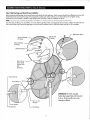
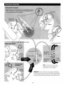
ANTENNA
ALIGNMENT
PROCEDURE
Satellite
Alignment
Alignment with the satellite
is
obtained
by
setting polarization, elevation, and azimuth. Charts are provided
in
this
manual to determine the
values for your earth station antenna
site
. "6L"
is
the difference between the earth station antenna
site
longitude and the satellite longitude.
Use
"6L" and your earth station latitude to obtain polarization, elevation or azimuth setting.
Polarization
of
Feed
Loosen
feed Horn clamp bolts and turn feed clockwise or counterclockwise,
depending on being east
or
west
of
the satellite
as
shown on Chart
1.
For coarse
setting, align marks on the horn scale. Polarization chart
assumes
antenna
system
polarization
is
transmit vertical and satellite vertical
Pol
is
perpendicular to plane
of
geostationary arc.
For
horizontal transmit
of
antenna, feed
must
be rotated
90
°
from values shown. (Starting point for polarization adjustment is 0°,
as
shown.
Use
a signal strength measuring device for final polarization setting and tighten horn
clamp bolts to
5.4
N-m (4 ft-
Ib).
Edge
of
Clar:'l"lP
Brack
et
Indicates
Degree of
Elev<:J
tion
Azimuth
-
Initial
Setting
Elevation Adjustment Screw
Elevation
-
Initial
Setting
Use
Chart 2 and determine your elevation setting.
Loosen
elevation pivot bolts and bolts
in
curved
slots
(both
sides)
of
az/el
housing approximately 1 complete turn.
Turn
elevation
adjustment bolt clockwise to decrease elevation and
counter-
clockwise to increase elevation. Align the edge
of
the clamp
with appropriate mark on housing at the desired elevation
reading.
This
will be an approximate setting. Optimum
setting achieved when fine tuning.
NOTE:
Degree
values
shown
on
E
levatio
n
Scale
are Be
am;
t
her
e
is
no
need
to
com
pensate
for
any
offse
t
angle.
(S
ee Appendix
A,
Outline
Dr
aw
in
g).
If
cl
in
ometer is
used,
yo
u
mus
t compensate for
offset
angl
e.
Use
Chart 3 and determine your azimuth setting. Values in chart
must
be adjusted for magnetic deviation for your location for correct
compass reading. Rotate reflector and mount pointing it to the correct compass reading. Slowly sweep the antenna
in
azimuth until
signal
is
found. If the desired signal
is
not found, increase or decrease elevation setting and repeat the azimuth sweep. Tighten half clamp
bolts and
set
screws.
Compass
• I Rotate Antenna
~
;;;
,/
On
Ground
Tube
1',-
- - - - - -
--"'-:e
....
_--,
_
...
Azimuth
Example
Depicts
Azimuth
Heading
To
171·
(Azimuth
±
Magnetic
Deviation)
Fine
Tuning
Use
Signal Tuning Device for final adjustments to obtain maximum antenna performance. Alternate between elevation and azimuth fine
tuning to reach maximum signal strength, until no improvement can be detected. Azimuth
is
fine tuned
by
loosening the
(4)
carriage head
bolts and swivel nut which allows adjusting the azimuth fine tune adjusting bolt for the peak signal.
When
fine tuning
is
complete, tighten
and torque
all
az/el
hardware to
16
.3 N-m
(12
ft-Ib)
. Do not exceed
16
.3 N-m
(12
ft-Ib).
Torque Clamp Hardware to 24.4 N-m
(18
ft-Ib)
in
alternating sequence.
IMPORTANT:
Rec
heck a
nd
repeat torque
on
four
cl
o
mp
bo
lt
s,
in
alternating
seque
nce,
until
all
bol
ts
are
equally
torqued
to
18
ft-Ib.
9

GROUNDING
PROCEDURE
INSTAllATION
POt.E
MOUNT
Note:
Grouna
~
~
wile
and
hardware are
not
~
u~
liedfor
pole
mount,
trimast
wall
moUnt
or
non
penetrating
roof
mOunt
",
.
lnstaliation
mount
and
assoc
i
dtt,td
hard
!?
re
are
not
supplied.
4
·p,0~
~~1
Screw
'tiJ
/ ' 0
Tooth
"
Washer
Non
Penetrating
.
Roof
Mount
10
Ground
Wire
(NEe
Section
810-20)
Class
I
Note:
Ground
w
ire
,
secure
clomp,
grounding
rod,
coaxial
cables
and
ground
block
are
not
suppl
i
ed.
IMPORTANT:
All
antenna
sytems
must
be properly grounded
Refer
to
NEC
(Notional
Electric
Code)
Article
810
,
820
and
locol
bUilding
codes
for
specific
requirements.
Typical
grounding
methods
are
shown
as
examples.
Tighten
all
hardware
securely
to
assure
good
continuity.

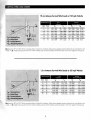
SURVIVAL
WIND
LOAD
CHARTS
96
em
Antenna
Survival
Wind
Loads
at
125
mph
Velocity
Elevation Degrees
Mech.
Beam
10
30
50
70
15
25
45
75
95
Force
N
IPaunds)
3
J~
2
3
3,
14
5
(707)
-667
(-150)
Moments
N-m
IFoot-Pounds)
t3c
056
~-
(6871
~
,""~'
:
1.~
86
;f'
(:
2
~§
t
-;;
~
""
~_
"
,,,,,
.
2,
76
7
(622)
·1
,8
37
171
(126)
2,592
(1
,
916)
~
2
;
4
3&
:
T
illl
~~
~
Y
215
lli~
';:
(l
O
Z
L
~
l§
§
~
~1
;q
8l2)
,j1=
2,
126
(478)
-2,438
(-548)
122
1,992
~
J
7z:
q:;
(~~
~
-2
"
~
5
~
49
",,.
;!-
:
~
1
,.;a
~~
kl~
:J.
_~
!=
:
~
\
1,330
(299)
-1,
971
(-
44
3)
73
(54)
1,246
(9
,
21)
MO based
on
937 mm (36.9
in)
from
mounting
surface
of
center
line
of
antenna
.
Values
shown
represen
t
maximum
forces
for
any
wind
direction
and
include
1
.5
FS
. H
eight
and
exposure
factors
from
uniform
building
code
are
NO
T
included.
Cen
t
er
line
based
on
36"
max.
height
of
mounting
post
.
1.2
m
Antenna
Survival
Wind
Loads
at
125
mph
Velocity
Elevation Degrees
Force
N
IPounds)
Moments
N-m
IFoat-Pounds)
~
~
___
~
~~9
~
'
~~~
'
=~
~~
-=
l
~
t
=~~
~
~~
·
~~~~
~
~
@~~
1
5115
(3
,7
80)
$.
~
4
969
ilL
(
?,6~~I
;
30
47
4,7
64
(1
,07
1)
-3
,
163
(-711)
571
(421)
4501
(3
,326)
,z~
~195
:
(
94
3
J
""3~--:
-:
(8
1
2.
jf :
85
7
~
·
'-
1{
8
4
;i
~
1
1
~--O--:-
-:-
j9
6
.r:
s
(2;
92
§ '
50
67
3,
656
(822)
-4
,
195
(-943)
405 (299) 3455
(2
,553)
~
='~
_~
__
6ffi:Ljj E 3,
0:5
J
1
68
6I
~
~
38
-L
!
1
:
2
8
,5J
i
~8
~i
!\
l~
;
130
)"
70
87
2,
291
(515)
-3
,390
(-762)
241
(1
7
8)
2585
(1
,
910)
MO based
on
945 mm (372
in)
from
mounting
surface
of
center
line
of
antenna
.
Values
shown
represent
maximum
forces
for
any
wind
direction
and
include
1.5
FS
. H
eight
and
exposure
factors
from
uniform
bUilding
code
are
NO
T
included.
Center
li
ne based
on
36
"
max.
height
of
mounting
post.
11

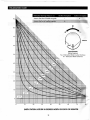
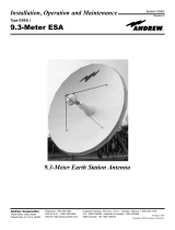
POLARIZATION
CHART
e
90
=H-
Polarization Chart Sign Values
(+
or
-) Northern Hemisphere
Southern Hem
is
pher
Antenna
Site West
of
Satellite longitude
-
+
I
Antenna Site
East
of
Satellite longitude
+
-
~
- -
0
80
,
J~
.........
+
-;;
~
-
70
Antenn
a
60
~~
~
FEED
ROTATION
(Facing Antenna)
For
+ Polarization Rotate Counter Clockwise
50
For
- Polarization Rotate Clockwise
.
b.7.5
°
40
b.60°
~
'""
30
b.3,
b.20
0
~
b.1
20
,b.
b.5°
10
b.2.5°
b.
o
o
10
20
30
40
50
60
70
80
EARTH
STATION
LATITUDE
IN
DEGREES
NORTH
OR
SOUTH
OF
EQUATOR
12

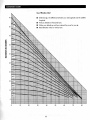
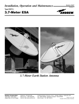
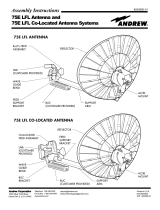
ELEVATION
CHART
Use
of
Elevation
Chart
90
ioo:I-l-++"I..
• Determine
il
= the difference between your
site
longitude and the satellite
longitude.
•
Find you latitude on horizontal axis.
• Follow your latitude up until you intersect
the
curve for your ~
.
•
Read
Elevation value on vertical axis.
10 I
d70
°
o
o
10
20
30
40
50
60
70
80
13

>
~
~
~
o
z
~
z
Z
....:.>
~~
~
~
z
C
m
~
~
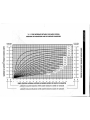
NORTHERN
HEMISPHERE
180
180
190
170
200
160
210
150
220
140
230 130
240 120
250
110
260
270
•
EAST
II
d
II
IS
THE
DIFFERENCE
BETWEEN
THE
EARTH
STATION
ANTENNA
SITE
LONGITUDE
AND
THE
SATELUTE
LONGITUDE
SOUTHERN
HEMISPHERE
~O
o
-t:tt.
0 _ 360
~75
°
~5
°
~
~
lO
a
-+:
~15
°
'~
~20
o
+-+1-
20
~
340
~25
°
r
~30
°
I I I I I I I
I-
~35
°
tl~...L.J
~40
0
I
111111
L~~~
:
I
1111111
L
~55~
r-
4
~60
0
~
~65
°
~
~70
0
...i I
P""
30
~
330
40
~
320
50
~
310
60
~
300
70
~
290
80
280
90
270
~
5 10
15
20
25
30
35 40 45
50
55 60 65
70
75
80
WEST
EAST
EARTH
STAnON
ANTENNA
LATmJDE
IN
DEGREES
NORTH
OR
SOU1H
OF
EQUATOR
~
"'---
AZIMUTH
COLUMN
READING
WHEN
EARTH
STATION
IS
WEST
OF
SATElLITE
AZIMUTH
COLUMN
READING
WHEN
EARTH
STATION
IS
EAST
OF
SATELLITE
>
~
~
~
o
z
~
z
z
>
~
~
Z
c
5
~
m
(I)

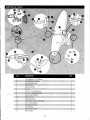
NO.
DESCRIPTION
QTY
.
3
4
5
6
96
em
Reflector
or
1.2
m
Reflector
Az
~
u
~
/Elevot
i
on
Assembly
.~-_-~~-=-~-~w~:~=~~~.~c~_'"~~
.
...;.
__
M8
x
60
mm
Plow
Bolt
M~loc
lli
Qsher
96
em
or
1.2
m Side Feed leg
96
em
~
1.2 mBottom Feed
le~
...:
.
,""--~_,;:"_,;""":,;",~~",,,,,=~
......
,,",..:.-_
9 M6 x 22
Hex
Head
Bolt
-1-0
---
......
---
M
~
6
lock
Woshe
~
=
-~:.::~_~""-"""~.;..;:;;.~~~~~
...
~
.. _
...
~_-===-
___
~
M6
Hex
Head
Nut
Junction
Block
wi
th
Pan
Head·Screws
.~~~~-~--,~
-~~-
..
~~~~--,-.~
13
M6 x
16
Hex
Head
Bolt
14
~
~
ntin9
Block
ClomR
-.--~-~--"'"
15
16
17
Feed Assembly
~~""--
M
-
~~
6Hex
!1
eod
Bolt
M6
Flat
Washer
is
15
4
4
2
3
3
2
1
2
2

PARTS
LIST
for
CLASS
II
NO.
DESCRIPTION
QTY.
NO.
DESCRIPTION
QTY.
NO.
DESCRIPTION
QTY.
96
cm
Reflector or 1.2 m Reflector
9 M6 x
22
Hex Head
Bolt
3
17
M6
Flat
Washer 4
~
~l~h
/EJeva~dn
As~e
;:;bty
-
M6 L6ckWasher 2
':%
10
11
'M6' x 16 Hex
Head
Bolt
2
~~'~
3
M8 x
60
mm
Plow
Bolt
4
11
M6 Hex
Head
Nut 5
19
M6x22
Round Head
2
M8
Feed"sul?Port
BlocJ(
~
Ci:~
Square Neck
Bolt
5
M8 Hex Head Nut
4
13
M6 x
20
Hex
Head
Bolt
2
Mount Brace
'2
Mo
~
tin§l
,
}
10
~~
mp
21
M8 x
20
Hex Head
Bolt
2
7
96
cm
or 1.2 m Side Feed
Leg
2
15
Feed Assembly
1
8
-~
96cm
'
inBotto
-;;;
Suppo
:al~
be
1
16
7
M6 x ,30 Hex t1ead
Bolt
2
16

-
~--

-
 1
1
-
 2
2
-
 3
3
-
 4
4
-
 5
5
-
 6
6
-
 7
7
-
 8
8
-
 9
9
-
 10
10
-
 11
11
-
 12
12
-
 13
13
-
 14
14
-
 15
15
-
 16
16
-
 17
17
-
 18
18
-
 19
19
-
 20
20


Andrew 123 1.2 Meter Class I Assembly Instructions Manual
- Category
- Television antennas
- Type
- Assembly Instructions Manual
- This manual is also suitable for
Ask a question and I''ll find the answer in the document
Finding information in a document is now easier with AI
Related papers
-
 Andrew Type 183 Assembly Instructions Manual
-
 Andrew 123 Class I User manual
-
 Andrew TYPE 120 User manual
-
 Andrew 3.7-Meter Earth Station Antenna User manual
-
 Andrew OM24SNG-RC User manual
-
 Andrew operation and maintenance User manual
-
 Andrew ES93 Installating And Operation Manual
-
 Andrew 75E LFL Co-Located Antenna Systems Assembly Instructions Manual
-
 Andrew ES93 User manual
-
Andrew ES45T User manual


Other documents
-
LG F10B5NDL25 Owner's manual
-
-
-
-
 KVH TracPhone Fleet One, FB250 & FB150 Installation guide
-
Home Decorators Collection 9434800240 Operating instructions
-
-
 Channel Master 183 Instruction And Assembly Manual
-
Ubiquiti Networks SWX-LBE5ACG2 User manual
-
Astonica 50103530 User manual

