Page is loading ...

7722483
Rev:
F

This document is for the following:
VHLP(X)6-*** 1.8m ANTENNA
7722483
B
RE
01
Bulletin
Rev
Status
Model Version
Version
Rev
Status
2 of 30
page
Installation Instructions
F
RE
05
Andrew Solutions
Customer Service 24 hours
U.S.A., Canada, Mexico: 1-800-255-1479
or 1-888-235-5732
U.K.: 0800 250055
Other Europe: +44 592 782 612
www.commscope.com\andrew
Visit our Web site at www.commscope.com\andrew or contact your local Andrew Solutions representative for more information.
© 2008 CommScope, Inc. All rights reserved.
Andrew Solutions is a trademark of CommScope. All trademarks identified by ® or ™ are registered trademarks or trade-
marks, respectively, of CommScope. This document is for planning purposes only and is not intended to modify or supplement
any specifications or warranties relating to Andrew Solutions products or services.
Notice: Andrew disclaims any liability or responsibility for the results of improper or unsafe installation, inspection, maintenance, or removal practices.
Aviso: Andrews no acepta ninguna obligacion ni responsabilidad como resultado de practicas incorrectas o peligrosas de instalacion, inspecci6n, mantenimiento o retire.
Avis : Andrew decline toute responsabilite pour les consequences de procedures d'installation, d'inspection, d'entretien ou de retrait incorrectes ou dangereuses.
Hinweis: Andrew lehnt jede Haftung Oder Verantwortung fur Schaden ab, die aufgrund unsachgemaBer Installation, Uberprufung, Wartung Oder Demontage auftreten.
Atencao: A Andrew abdica do direito de toda responsabilidade pelos resultados de praticas inadequadas e sem seguranca de instalacao, inspecao, manutengao ou remocao.
Awertenza: Andrew declina eventual! responsabilita denvanti dell'esecuzione di procedure di installazione, ispezione, manutenzione e smontaggio improprie o poco sicure.
ValuLine
®
6ft (1.8m) Antennas

This instruction describes how to assemble a VHLP(X)6 antenna.
The antenna can be mounted to the left or to the right of the supporting structure.
These instructions describe how to mount the antenna to the left of the supporting stucture,
however instructions showing the antenna mounted to the right of the supporting structure are
included where appropriate. It is recommended that at least 2 persons assemble the antenna.
INTRODUCTION
Page 3 of 30
7722483
CONTENTS & INTRODUCTION
SECTION 1
INSTALLATION
INSTRUCTIONS

Page 4 of 30
7722483
SAFETY INSTRUCTIONS
SECTION 2
INSTALLATION
INSTRUCTIONS

Page 5 of 30
7722483
SAFETY INSTRUCTIONS
SECTION 2
INSTALLATION
INSTRUCTIONS

Table 1 Supplied Equipment and Tools
Page 6 of 30
7722483
EQUPMENT AND TOOLS
SECTION 3
INSTALLATION
INSTRUCTIONS
Item
Qty
Description
Contained in Kit Part No
A
1
Reflector
B
1
Shield Set
C
1
Radome
D
1
Feed (frequency dependant)
D1
6ft Feed Hardware Kit
7625043
4
M4 x 16lg SHCS, sst, pass
4
M4 Lock Washer, sst, pass
1
Conductive Grease (tube)
2
Gloves
D2
Vertex Plate Kit (6GHz & 11GHz only)
7714550-FR-KIT
2
Vertex Plate
4
M4 x 10lg SHCS, sst, pass
E
Elevation Pivot Bar - Top
F
Vertical Support Channel
G
Mount Kit - 6ft
7770572
G1
1
Elevation Pivot Bar - Bottom
G2
3
Spacer Plate
G3a
1
Elevation Pivot Bracket - Top Right
G3b
1
Elevation Pivot Bracket - Top Left
G4
1
Elevation Pivot bracker - Bottom
G5
1
Safety Bracket
H
Shield Hardware Kit
7719422
H1
62
M6 x 20 Hex Hd Screw, sst, pass
124
M6 Washer, sst, pass
62
M6 Lock Washer, sst, pass
62
M6 Nut, sst, pass
H2
40
M6 x 25 Skt Hd Cap Screw, sst, pass
40
M6 Large Washer, sst, pass
J
Mount Hardware Kit
7714342
J1 3
M16 U-Bolt c/w Nuts & Washers
J2 4
M12 x 40lg Carriage Bolt
4
M12 Nut, stl, galv
4
M12 Lock Washer, stl, galv
4
M12 Washer, stl, galv
4
M16 Washer, stl, galv
J3 1
M16 Eye Bolt, stl, galv
2
M16 Washer, stl, galv
2
M16 Nut, stl, galv
1
M12 x 45lg Hex Hd Screw, stl, galv
1
M12 Lock Washer, stl, galv
1
M12 washer, stl, galv
1
M12 Nut, stl, galv
J4 2
M16 x 45lg Hex Hd Screw, stl, galv
2
M16 Lock Washer, stl, galv
4
M16 Washer, stl, galv
2
M16 Nut, stl, galv
J5 9
M10 x 35lg Hex Hd Screw, sst, pass
9
M10 Lock Washer, sst, pass
9
M10 Washer, sst, pass

Table 1 Supplied Equipment and Tools
Page 7 of 30
7722483
EQUIPMENT AND TOOLS
SECTION 3
INSTALLATION
INSTRUCTIONS
Item
Qty
Description
Contained in Kit Part No
K
Strut Hardware Kit
7721920
K1
1
Spacer Plate
1
Brce Rod Attachment Bracket
1
M12 X 35lg Hex Hd Screw, stl, galv
1
M12 Lock Washer, stl, galv
1
M12 Washer, stl, galv
3
M10 x 35lg Hex Hd Screw, sst, pass
3
M10 Lock Washer, sst, pass
3
M10 Washer, sst, pass
K2
Azimuth Adjuster Assembly
P99915 (supplied assembled)
1
Azimuth Adjuster Bracket
1
Adjuster Plate Bracket
2
Clamp Bracket
1
Swivel Plate
1
M16 x 390lg Eye Bolt, stl, galv
2
M12 U-Bollt c/w Nuts and Washers
1
M12 x 180lg Stud, stl, galv
1
M12 X 140lg Hex Hd Screw, stl, galv.
1
M12 x 60lg Skt Hd C'sk Screw, stl, galv
9
M12 Nut, stl, galv
7
M12 Washer, stl, galv
1
M12 Lock Washer, stl, galv
1
M12 Washer, stl, galv
L
1
Brace Rod

TOOL REQUIRMENTS
Tools
Page 8 of 30
7722483
EQUIPMENT AND TOOLS
SECTION 3
INSTALLATION
INSTRUCTIONS
Tools Required
Bolt Diameter in MM
M4 M6 M10 M12 M16
Ring and Open spanner (A/F)
10mm 17mm 19mm 24mm
Torque Wrench
2.5 - 95Nm
Sockets (A/F)
10mm 17mm 19mm 24mm
Allen Key (A/F)
3mm 5mm 8mm
General Toolbox

A
B
C
D
D2
D1
Page 9 of 30
7722483
EQUIPMENT AND TOOLS
SECTION 3
INSTALLATION
INSTRUCTIONS

J1
J2
J4
J5
J3
K1
K2
G1
G2
G4
G3a
G5
G3b
H1
H2
L
E
F
Page 10 of 30
7722483
EQUIPMENT AND TOOLS
SECTION 3
INSTALLATION
INSTRUCTIONS

A
Leave packing struts in place during
assembly until directed to remove.
(ommited on subsequent views for clarity)
Page 11 of 30
7722483
UNPACKING
SECTION 4
INSTALLATION
INSTRUCTIONS
Instructions for unpacking crate:
Wire bound crate:
1. Release wire tabs at one side of the crate.
2. The crate panel will hinge open along the opposite side from the
released wire tabs.
Nailed crate:
1. Carefully remove panel to allow access to shields and reflector struts.
Remove components:
3. Remove shields, strut and integration/omt kit.
4. Remove nails from top of packing strut, the reflector can then be hinged
backwards along the bottom edge and removed from the crate, handle
reflector
CAREFULLY
at all times.
5. Leave reflector attached to the backing struts until instructed to remove.
6. Remove radome and feed.
7. Open kit boxes and remove components as required.
Handle reflector
CAREFULLY at
all times

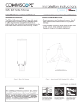
Shield assembly sequence
Left (-L)
Top (-T)
Right (-R)
Bottom (-B)
B
Top
(T)
Left
(L)
Right
(R)
Bottom
(B)
Antenna shield
arrangement
shield overlap
arrangement
T
B
R
L
ATTENTION
Align slots in shields
to holes in reflector
Page 12 of 30
7722483
SECTION 5
INSTALLATION
INSTRUCTIONS
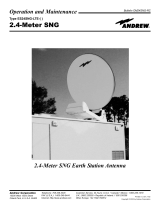
ASSEMBLY OF REFLECTOR TO SHIELD

H1
Flat
washers
Lock
washer
Threaded inserts
for radome
attachment
Drain hole
Reflector
attachment
slots
Drain hole
Insert shield in to reflector so that attachment slots
align with rim holes in reflector
Ensure highest side of
shield set is aligned to
top of antenna
Align shield slots and reflector
holes to receive a bolt.
Repeat at 90 degree intervals.
Align red tape on
reflector with
red tape on shield
Fit loosely with flat washers,
lock washer and nut in 4
positions as directed then tighten.
H1
Flat
washers
Lock
washer
Page 13 of 30
7722483
SECTION 5
INSTALLATION
INSTRUCTIONS
ASSEMBLY OF REFLECTOR TO SHIELD

Fit bolts, washers, lock washers and nuts to
remaining holes of assembly and tighten.
Tighten all shield and segment fastenings
to 7.7Nm
5%
H1
Page 14 of 30
7722483
SECTION 5
INSTALLATION
INSTRUCTIONS
ASSEMBLY OF REFLECTOR TO SHIELD

D2
Tighten to 2.5Nm
5%
D
Page 15 of 30
7722483
SECTION 6
INSTALLATION
INSTRUCTIONS
FEED ATTACHMENT AND ALIGNMENT
***6GHz and 11GHz Only**
Vertex Plate Assembly

REFER TO SAFETY NOTE ON PAGE 5
D
Align flat of feed hub to
red tape of reflector
Apply grease to
surfaces indicated
Ensure flat of feed hub is
assembled in a horiziontal (top)
position and aligned with red
tape of reflector
Page 16 of 30
7722483
SECTION 6
INSTALLATION
INSTRUCTIONS
FEED ATTACHMENT AND ALIGNMENT
Prior to feed attachment, carefully
tilt antenna upright using packing
struts and hold in position.
Do not apply excesive weight to
antennas assembly.

D1
Torque to 2.5Nm
5%
Page 17 of 30
7722483
SECTION 6
INSTALLATION
INSTRUCTIONS
FEED ATTACHMENT AND ALIGNMENT
After assembly, remove excess grease from internal reflector surface.

Unfold radome on to a
clear, flat and dry surface
and assemble radome rim
tensioners at 8 places.
Lift radome and
secure tabs over
hooks
Ensure radome tensioners
are pressed fully home.
(When fully pressed home,
tensioners are no longer
loose or removable)
H2
To correctly align radome
attachment slots.
Align a radome tensioner
with a shield assembly seam.
Torque to 7.7Nm
5%
Assemble radome to shields
with screws and washers
Page 18 of 30
7722483
SECTION 7
INSTALLATION
INSTRUCTIONS
RADOME ATTACHMENT
After feed attachment, carefully
lay antenna flat.

Antenna assembled
to left of support
structure
Antenna assembled
to right of support
structure
Page 19 of 30
7722483
SECTION 8
INSTALLATION
INSTRUCTIONS
MOUNT ATTACHMENT AND ALIGNMENT
Prior to assembly of mount to antenna, determine the
desired installation configuration.

J5
G2
G3b
G3a
G4
G2
G2
Loosely tighten all screws until
mount has been fully assembled.
Top of antenna
(red tape)
Mount bracket orientation for mounting antenna
to the left of the support structure
For mounting the antenna to the right of the supporting structure
assemble bracket G4 along with associated plate G2 in position indicated.
G3b
G3a
G4
G4 & G2 position for
left side installation
Page 20 of 30
7722483
SECTION 8
INSTALLATION
INSTRUCTIONS
MOUNT ATTACHMENT AND ALIGNMENT
Carefully lay antenna on clear, flat
ground and remove packing struts..
Do not apply excesive weight to
antennas assembly.
/