Page is loading ...

Publication 1746-IN015C-EN-P - July 2001
Installation Instructions
SLC 500 Thermocouple/mV Analog Input Module
(Catalog Number 1746-NT8)
Inside...
Hazardous Location Considerations ........................................................ 2
Environnements dangereux ..................................................................... 2
Module Overview..................................................................................... 3
Input Ranges ............................................................................................ 3
Hardware Features .................................................................................. 4
Installing And Wiring Your Module ......................................................... 5
Electrostatic Damage............................................................................... 6
Required Tools and Equipment................................................................ 6
Power Requirements................................................................................ 6
Considerations for a Modular System ..................................................... 7
Considerations for a Fixed Controller ...................................................... 7
Selecting A Chassis Slot.......................................................................... 7
Module Installation and Removal............................................................ 8
Terminal Block Removal........................................................................... 9
Cold Junction Compensation (CJC) ....................................................... 10
Wiring Guidelines .................................................................................. 10
Thermocouple Junctions........................................................................ 11
Preparing and Wiring the Cables........................................................... 14
Module Specifications........................................................................... 17
For More Information ............................................................................. 20

2 SLC 500 Thermocouple/mV Analog Input Module
Publication 1746-IN015C-EN-P - July 2001
Hazardous Location Considerations
This equipment is suitable for use in Class I, Division 2, Groups A, B, C, D or
non-hazardous locations only. The following WARNING statement applies to use in
hazardous locations.
Environnements dangereux
Cet équipement est conçu pour être utilisé dans des environnements de Classe I,
Division 2, Groupes A, B, C, D ou non dangereux. La mise en garde suivante
s’applique à une utilisation dans des environnements dangereux.
WARNING
!
EXPLOSION HAZARD
• Substitution of components may impair suitability for Class
I, Division 2.
• Do not replace components or disconnect equipment
unless power has been switched off or the area is known to
be non-hazardous.
• Do not connect or disconnect components unless power
has been switched off or the area is known to be
non-hazardous.
• All wiring must comply with N.E.C. article 501-4(b).
AVERTISSEMENT
!
DANGER D’EXPLOSION
• La substitution de composants peut rendre cet équipement
impropre à une utilisation en environnement de Classe I,
Division 2.
• Ne pas remplacer de composants ou déconnecter
l'équipement sans s'être assuré que l'alimentation est
coupée.
• Ne pas connecter ou déconnecter des composants sans
s'être assuré que l'alimentation est coupée.

SLC 500 Thermocouple/mV Analog Input Module 3
Publication 1746-IN015C-EN-P - July 2001
Module Overview
The module communicates with the SLC 500 processor and receives +5V dc and
+24V dc power from the system power supply through the parallel backplane
interface. No external power supply is required. You may install as many
thermocouple modules in the system as the power supply can support.
Each module channel can receive input signals from a thermocouple or a millivolt
analog input device. You configure each channel to accept either one. The module
converts analog input voltages when it is configured for thermocouple input types.
The analog input voltages are converted into cold-junction compensated, digital
temperature readings. The module uses the National Institute of Standards and
Technology (NIST) based on ITS-90 for thermocouple linearization.
When configured for millivolt analog inputs, the module converts analog values
directly into digital counts. The module assumes that the mV input signal is linear
prior to input to the module.
Input Ranges
The following two tables define thermocouple types and associated temperature
ranges and the millivolt analog input signal ranges that each of the module’s input
channels will support. To determine the practical temperature range of your
thermocouple, refer to the specifications in Appendix A of the SLC 500
Thermocouple/mV Analog Input Module User Manual, publication 1746-6.22.
Table A Thermocouple Temperature Ranges
Type °C Temperature Range °F Temperature Range
J -210 °C to 760 °C -346 °F to 1400 °F
K -270 °C to 1370 °C -454 °F to 2498 °F
T -270 °C to 400 °C -454 °F to 752 °F
B 300 °C to 1820 °C 572 °C to 3308 °F
E -270 °C to 1000 °C -454 °F to 1832 °F
R 0 °C to 1768 °C 32 °F to 3214 °F
S 0 °C to 1768 °C 32 °F to 3214 °F
N 0 °C to 1300 °C 32 °F to 2372 °F
CJC Sensor -25 °C to 105 °C -13 °F to 221 °F
Table B Millivolt Input Ranges
(1)
(1) Output impedance of input device must be less than 100 Ω to meet accuracy specifications.
-50 to +50 mV -100 to +100 mV

4 SLC 500 Thermocouple/mV Analog Input Module
Publication 1746-IN015C-EN-P - July 2001
Each input channel is individually configured for a specific input device. Each
channel detects and indicates:
• open-circuit
• over-range
• under-range
Hardware Features
The module fits into any single slot (other than slot 0) for I/O modules in either an
SLC 500 modular system or an SLC 500 fixed system expansion chassis (1746-A2). It
is a Class 1
(1)
module (uses 8 input words and 8 output words).
The module contains a removable terminal block providing connections for eight
thermocouple and/or analog input devices. On the terminal block are two
cold-junction compensation (CJC) sensors that compensate for the cold junction at
ambient temperature. It should also be noted there are no output channels on the
module. Configure the module with software rather than with jumpers or switches.
(1) Requires use of a Block Transfer in a remote configuration.
IMPORTANT
There is a jumper (JP1) on the circuit board. The module is
shipped with the jumper in the up position as illustrated below.
Do not change the position of JP1. The jumper is used for test
purposes only.
JP1
Jumper - Do Not move.

SLC 500 Thermocouple/mV Analog Input Module 5
Publication 1746-IN015C-EN-P - July 2001
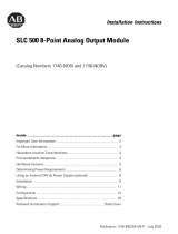
1746-NT8 Features
Installing And Wiring Your Module
Read this section to install and wire your module. This section covers:
• avoiding electrostatic damage
• determining power requirements
• installing the module
• wiring signal cables to the module’s terminal block
Hardware Function
Channel Status LED Indicators Display operating and fault status of channels 0 through 7
Module Status LED Displays operating and fault status of the module
Side Label (Nameplate) Provides module information
Removable Terminal Block Provides electrical connection to input devices
Door Label Permits easy terminal identification
Self Locking Tabs Secure module in chassis slot
MODULE
0
1
4
5
2
1
2
3
CHANNEL
STATUS
THERMOCOUPLE/mV
INPUT
CJC A+
CJC A-
CHL 0+
CHL 0-
SHIELD
CHL 1+
CHL 1-
CHL 2+
CHL 2-
SHIELD
CHL 3+
CHL 3-
CHL 4+
CHL 4-
SHIELD
CHL 5+
CHL 5-
CHL 6+
CHL 6-
SHIELD
CHL 7+
CHL 7-
CJC B+
CJC B-
1746-NT8
Door Label
Channel Status
LEDs (Green)
Module Status
LED (Green)
Removable Terminal Block
CJC Sensors
Cable Tie Slots

6 SLC 500 Thermocouple/mV Analog Input Module
Publication 1746-IN015C-EN-P - July 2001
Electrostatic Damage
Electrostatic discharge can damage semiconductor devices inside this module if you
touch backplane connector pins. Guard against electrostatic damage by observing
the following precautions:
Required Tools and Equipment
Have the following tools and equipment ready:
• 2.5 mm (0.1 in.) slot-head screwdriver
• thermocouple or millivolt sensor
• appropriate thermocouple extension wire (if needed)
• thermocouple/mV input module (1746-NT8)
• programming equipment
Power Requirements
The module receives its power through the SLC 500 chassis backplane from the
fixed or modular +5V dc/+24V dc chassis power supply. The maximum current
drawn by the module is shown in the following table.
ATTENTION
!
ELECTROSTATICALLY SENSITIVE COMPONENTS
• Before handling the module, touch a grounded object to rid
yourself of electrostatic charge.
• Handle the module from the front, away from the
backplane connector. Do not touch backplane connector
pins.
• Keep the module in its static-shield container when not in
use or during shipment.
Failure to observe these precautions can degrade the module’s
performance or cause permanent damage.
Table C Maximum Current Drawn By the Module
5VDC Amps 24VDC Amps
0.120 0.070

SLC 500 Thermocouple/mV Analog Input Module 7
Publication 1746-IN015C-EN-P - July 2001
Considerations for a Modular System
Place your module in any slot of an SLC 500 modular, or modular expansion
chassis, except for the left-most slot (slot 0) reserved for the SLC processor or
adapter modules.
Considerations for a Fixed Controller
The power supply in the 2-slot SLC 500 fixed I/O chassis (1746-A2) can support
only specific combinations of modules. Make sure the chassis power supply can
support the 1746-NT8 and additional module power requirements.
Selecting A Chassis Slot
Two factors determine where you should install your module in the chassis:
ambient temperature and electrical noise. When selecting a slot for your module,
try to position your module:
• in a chassis close to the bottom of the enclosure (where the air is cooler)
• away from modules that generate significant heat, such as the 1746-OA16 or
the 1746-IA16
• in a slot away from ac or high-voltage dc modules, hard contact switches,
relays, and ac motor drives
• away from the chassis power supply (if using a modular system)
Remember that in a modular system, a processor or adapter always occupies the
first slot of the chassis.

8 SLC 500 Thermocouple/mV Analog Input Module
Publication 1746-IN015C-EN-P - July 2001
Module Installation and Removal
To insert your module into the chassis, follow these steps:
1. Before installing the module, connect ground wire to TB1. See page 15.
2. Align the circuit board of your module with the card guides at the top and
bottom of the chassis.
3. Slide your module into the chassis until both top and bottom retaining clips
are secure. Apply firm even pressure on your module to attach it to its
backplane connector. Never force your module into the slot.
4. Cover all unused slots with the Card Slot Filler, Allen-Bradley part number
1746-N2.
ATTENTION
!
Before installing or removing your module, always disconnect:
• power from the SLC 500 system
• any other power sources to the module
• any devices wired to the module
Failure to observe this precaution can cause unintended
equipment operation and damage.
Top and Bottom Module
Release(s)
Card Guide

SLC 500 Thermocouple/mV Analog Input Module 9
Publication 1746-IN015C-EN-P - July 2001
Terminal Block Removal
To remove the terminal block:
1. Loosen the two terminal block release screws. To avoid cracking the
terminal block, alternate between screws as you remove them.
2. Using a screwdriver or needle-nose pliers, carefully pry the terminal block
loose. When removing or installing the terminal block be careful not to
damage the CJC sensors.
Terminal Block Diagram with CJC Sensors
ATTENTION
!
POSSIBLE EQUIPMENT OPERATION
Before wiring your module, always disconnect power from the
SLC 500 system and from any other source to the module.
Failure to observe this precaution can cause unintended
equipment operation and damage.
Terminal Block Release Screws
CJC Sensors
CJC Sensors
Terminal Block Release Screws

10 SLC 500 Thermocouple/mV Analog Input Module
Publication 1746-IN015C-EN-P - July 2001
Cold Junction Compensation (CJC)
To obtain accurate readings from each of the channels, the cold-junction
temperature (temperature at the module’s terminal junction between the
thermocouple wire and the input channel) must be compensated for. Two cold
junction compensating sensors are integrated in the removable terminal block.
They must remain installed to retain accuracy.
Wiring Guidelines
Isolation
The 1746-NT8 module provides the following electrical isolation:
• 12.5V dc electrical isolation channel to channel
• 500V dc for 1 minute electrical isolation channel to chassis ground
• 500V dc for 1 minute electrical isolation channel to backplane
Care must be taken when choosing a thermocouple type and connecting it to the
1746-NT8 module from the environment being measured. If adequate precautions
are not taken for a given thermocouple type, the electrical isolation of the 1746-NT8
module may be compromised.
ATTENTION
!
Do not remove or loosen the cold junction compensating
temperature transducers located on the terminal block. Both
CJCs are critical to ensure accurate thermocouple input readings
at each channel. The module will not operate in thermocouple
mode if a CJC is not connected.
Failure to observe this precaution can cause unintended
equipment operation and damage.

SLC 500 Thermocouple/mV Analog Input Module 11
Publication 1746-IN015C-EN-P - July 2001
Thermocouple Junctions
There are three types of thermocouple junctions:
• Grounded Junction - The measuring junction is physically connected to the
protective metal sheath providing electrical continuity between junction and
sheath.
• Ungrounded Junction - The measuring junction is electrically isolated from
the protective metal sheath. (Ungrounded Junction can also be called
Insulated Junction.)
• Exposed Junction - Does not have a protective metal sheath so the
measuring junction is exposed.
Grounded Junction Thermocouples
As shown in the following illustration, the shield input terminals are internally
connected together, which are then connected to chassis ground. Using grounded
junction thermocouples with electrically conductive sheaths removes the
thermocouple signal to chassis ground isolation of the module. This is inherent to
the thermocouple construction. In addition, if multiple grounded junction
thermocouples are used, the module’s channel-to-channel isolation is removed
since there is no isolation between signal and sheath and the sheaths are tied
together. It should be noted that the isolation is removed even if the sheaths are
connected to chassis ground at a location other than the module, since the module
is connected to chassis ground.
TIP
Refer to Appendix A of the SLC 500 Thermocouple/mV Analog
Input User Manual, publication 1746-6.22 for additional
information on wiring and using grounded junction,
ungrounded junction, and exposed junction thermocouple
types.

12 SLC 500 Thermocouple/mV Analog Input Module
Publication 1746-IN015C-EN-P - July 2001
Grounded Junction Thermocouples
As shown in the wiring diagram above, it is recommended that grounded junction
thermocouples have either protective sheaths made of electrically insulated material
(e.g. ceramic), or that the metal protective sheaths be floated. The metal sheaths
would need to be floated with respect to any path to chassis ground or to another
thermocouple metal sheath. This means the metal sheath must be insulated from
electrically conductive process material and have all connections to chassis ground
broken. It should be noted that a floated sheath may result in a less noise-immune
thermocouple signal.
Exposed Junction Thermocouples
Recommended wiring for exposed junction thermocouples is shown in the
following illustration. Using exposed junction thermocouples may result in removal
of channel-to-channel isolation. This may occur if multiple exposed thermocouples
are in direct contact with electrically conductive process materials. To prevent
violation of channel-to-channel isolation:
• For multiple exposed thermocouples, do not allow the measuring junction
of the thermocouple to make direct contact with electrically conductive
process material.
• Use all ungrounded junction thermocouples instead of the exposed junction
type.
+
-
+
-
1746-NT8
Grounded junction with nonconductive
protective sheath
CH0
MUXES
CH3
Metal sheath with electrical continuity to
thermocouple signal wires.
(floating ground connection)

SLC 500 Thermocouple/mV Analog Input Module 13
Publication 1746-IN015C-EN-P - July 2001
Exposed Junction Thermocouples
Cable Wiring Considerations
Follow these guidelines to wire your input signal cables:
• Power, input, and output (I/O) wiring must be in accordance with Class 1,
Division 2 wiring methods [Article 501-4(b) of the National Electrical Code,
NFPA 70] and in accordance with the authority having jurisdiction.
• Route the field wiring away from any other wiring and as far as possible
from sources of electrical noise, such as motors, transformers, contactors,
and ac devices. As a general rule, allow at least 15.2 cm (6 in.) of separation
for every 120 V of power.
• Routing the field wiring in a grounded conduit can reduce electrical noise
further.
• If the field wiring must cross ac or power cables, ensure that they cross at
right angles.
• To limit the pickup of electrical noise, keep thermocouple and millivolt
signal wires as far from power and load lines as possible.
• For high immunity to electrical noise, use Belden™ 8761 (shielded, twisted
pair) or equivalent wire for millivolt sensors; you can also use shielded,
twisted pair thermocouple extension lead wire specified by the
thermocouple manufacturer. Using the incorrect type of thermocouple
extension wire or not following the correct polarity may cause invalid
readings.
+
-
+
-
1746-NT8
Conductive Material
Exposed junction with
shielded cable
CH 0
MUXES
Nonconductive Material
Exposed junction with
shielded cable
CH 3

14 SLC 500 Thermocouple/mV Analog Input Module
Publication 1746-IN015C-EN-P - July 2001
• Ground the shield drain wire at only one end of the cable. The preferred
location is at the shield connections on the terminal block. (Refer to IEEE
Std. 518, Section 6.4.2.7 or contact your sensor manufacturer for additional
details.)
• Keep all unshielded wires as short as possible.
• Excessive tightening can strip a screw. Tighten screws no more than
0.25 Nm.
• Follow system grounding and wiring guidelines found in your SLC 500
Installation and Operation Manual.
Preparing and Wiring the Cables
To prepare and connect cable leads and drain wires, follow these steps:
1. At each end of the cable, strip some casing to expose individual wires.
2. Trim signal wires to 5-inch lengths beyond the cable casing. Strip about
4.76 mm (0.1875 in.) of insulation to expose the ends of the wires.
3. At the module-end of the cables:
• extract the drain wire and signal wires
• remove the foil shield
• bundle the input cables with a cable strap
4. Connect the following pairs of drain wires together.
• Channels 0 and 1
• Channels 2 and 3
• Channels 4 and 5
• Channels 6 and 7
Keep drain wires as short as possible.
(Remove foil shield and
drain wire from sensor-end
of the cable.)
Cable
Drain Wire
Signal Wires
Signal Wires

SLC 500 Thermocouple/mV Analog Input Module 15
Publication 1746-IN015C-EN-P - July 2001
5. Connect the drain wires to the shield inputs of the terminal block if
appropriate for thermocouple used. See “Wiring Guidelines” on page 10 for
more information.
• Channel 0 and 1 drain wires to pin 5
• Channel 2 and 3 drain wires to pin 10
• Channel 4 and 5 drain wires to pin 15
• Channel 6 and 7 drain wires to pin 20
6. Connect the signal wires of each channel to the terminal block.
7. Connect TB1 chassis ground connector to the nearest chassis mounting bolt
with 14 gauge wire. (On the face of the module, TB1 is near the lower part
of the terminal block on the primary side of the PCB.)
8. At the sensor-end of cables from thermocouple/mV devices:
• remove the drain wire and foil shield
• apply shrink wrap as an option
• connect to thermocouple/mV devices keeping the leads short
IMPORTANT
Only after verifying that your connections are correct for
each channel, trim the lengths to keep them short. Avoid
cutting leads too short.
IMPORTANT
If noise persists, try grounding the opposite end of the cable
instead. (Ground one end only.)
TB1
Connect ground wire to TB1 before installing module.

16 SLC 500 Thermocouple/mV Analog Input Module
Publication 1746-IN015C-EN-P - July 2001
Terminal Block Diagram with Input Cable
Thermocouple or mV Cable
TB1
CJC A+
CJC A-
Channel 0+
Channel 0-
Shield for CH0 and CH1
Channel 1+
Channel 1-
Channel 2+
Channel 2-
Shield for CH2 and CH3
Channel 3+
Channel 3-
Channel 4+
Channel 4-
Shield for CH4 and CH5
Channel 5+
Channel 5-
Channel 6+
Channel 6-
Shield for CH6 and CH7
Channel 7+
Channel 7-
CJC B+
CJC B-

SLC 500 Thermocouple/mV Analog Input Module 17
Publication 1746-IN015C-EN-P - July 2001
Module Specifications
Electrical Specifications
Physical Specifications
Backplane Current Consumption 120 mA at 5V dc, 70 mA at 24V dc
Backplane Power Consumption 2.28W maximum (0.5W at 5V dc, 1.68W at 24V dc)
Number of Channels 8 (backplane and channel-to-channel isolated)
I/O Chassis Location Any I/O module slot except 0
A/D Conversion Method Sigma-Delta Modulation
Input Filtering Low pass digital filter with programmable notch (filter)
frequencies
Normal Mode Rejection
(between [+] input and [-] input)
Greater than 100 dB at 50/60 Hz
Common Mode Rejection
(between input and ground)
Greater than 100 dB at 50/60 Hz
Input Filter Cut-Off Frequencies
2.6 Hz at 10 Hz filter frequency
13.1 Hz at 50 Hz filter frequency
15.72 Hz at 60 Hz filter frequency
65.5 Hz at 250 Hz filter frequency
Greater than 100 dB at 50/60 Hz
Calibration Module autocalibrates at power-up and approximately
every two minutes thereafter
Input Over voltage Protection ±30V dc continuous, 600W pulsed for 1 msec.
Isolation 500V dc for 1 minute between inputs and chassis
ground, and between inputs and backplane.
12.5V dc continuous between channels.
LED Indicators 9 green status indicators, one for each of 8 channels
and one for module status
Module ID Code 3533
Maximum Wire Size One 14 AWG wire or two 22 AWG wires per terminal
Replacement Terminal Block 1746-RT34

18 SLC 500 Thermocouple/mV Analog Input Module
Publication 1746-IN015C-EN-P - July 2001
Environmental Specifications
Input Specifications
Operating Temperature 0°C to +60°C (+32°F to +140°F)
Storage Temperature -40°C to +85°C (-40°F to +185°F)
Relative Humidity 5% to 95% (without condensation)
Agency Certification UL and C-UL approved
Hazardous Environment Classification Class I, Division 2 Hazardous Environment Groups A, B, C, D
EMC CE compliant for all applicable directives
C-Tick compliant for all applicable acts
Type of Input (Selectable) Thermocouple Type J -210°C to +760°C (-346°F to +1400°F)
Thermocouple Type K -270°C to +1370°C (-454°F to +2498°F)
Thermocouple Type T -270°C to +400°C (-454°F to +752°F)
Thermocouple Type E -270°C to +1000°C (-454°F to +1832°F)
Thermocouple Type R 0°C to +1768°C (+32°F to +3214°F
Thermocouple Type S 0°C to +1768°C (+32°F to +3214°F)
Thermocouple Type B +300°C to +1820°C (+572°F to +3308°F)
Thermocouple Type N 0°C to +1300°C (+32°F to +2372°F)
Millivolt (-50 mV dc to +50 mV dc)
Millivolt (-100 mV dc to +100 mV dc)
Thermocouple Linearization NIST ITS-90 standard
Cold Junction Compensation Accuracy ±1.72°C, -25°C to +105°C Analog Devices AD592CN
Module Input Impedence Greater than 10M Ω
Input Device Impedence Output impedance of input device must be less than 100 Ω to meet
accuracy specifications.
Temperature Scale (Selectable) °C or °F and 0.1°C or 0.1°F
DC Millivolt Scale (Selectable) 0.1 mV or 0.01 mV
Open Circuit Detection
(Selectable)
Upscale, Downscale, Zero, or Disabled
Time to Detect Open Circuit One channel cycle time
Input Step Response 0 to 95% in 400 msec (10 Hz)
Display Resolution See Channel Data Word Resolution table in Chapter 4 of the
SLC 500™
Thermocouple/mV Analog Input Module
manual, publication 1746-6.22.

SLC 500 Thermocouple/mV Analog Input Module 19
Publication 1746-IN015C-EN-P - July 2001
Overall Module Accuracy at 25°C
(77°F)
See Module Accuracy Tables, in Appendix A of the
SLC 500™
Thermocouple/mV Analog Input Module
manual, publication 1746-6.22.
Overall Module Accuracy (0°C to
60°C, 32°F to 140°F)
See Module Accuracy Tables, in Appendix A of the
SLC 500™
Thermocouple/mV Analog Input Module
manual, publication 1746-6.22.
Overall Module Drift See Module Accuracy Tables, in Appendix A of the
SLC 500™
Thermocouple/mV Analog Input Module
manual, publication 1746-6.22.
Module Update Time Dependent upon enabled channels (see Update Time, in the
SLC 500™
Thermocouple/mV Analog Input Module
manual, publication 1746-6.22)
Channel Turn-Off Time Up to one module update time

Publication 1746-IN015C-EN-P - July 2001 PN 40071-124-01(C)
Supersedes Publication 1746-IN015B-EN-P - March 2001 © 2001 Rockwell International Corporation. Printed in the U.S.A.
For More Information
How to Get More Information
If you would like a manual, you can:
• download a free electronic version from the internet at
www.theautomationbookstore.com
• purchase a manual by:
– contacting your local distributor or Rockwell Automation representative
– visiting www.theautomationbookstore.com and placing your order
– calling 1.800.963.9548 (USA/Canada) or
001.330.725.1574 (Outside USA/Canada)
SLC 500 is a trademark of Rockwell Automation.
Belden is a trademark of Belden, Inc.
For Refer to this Document Pub. No.
A more detailed description on how to install
and use your SLC 500™ Thermocouple/mV
Input Module
SLC 500™ Thermocouple/mV
Analog Input Module User Manual
1746-6.22
A more detailed description on how to install
and use your SLC 500™ Modular Hardware
Style Control System.
SLC 500™ Modular Hardware
Style Installation and Operation
Manual
1747-6.2
More information on proper wiring and
grounding techniques.
Automation Wiring and Grounding
Guidelines
1770-4.1
/