
1
Cable Cubby 1252 MS • Installation Guide
This guide provides instructions for an experienced technician to install the Extron
Cable Cubby 1252 MS.
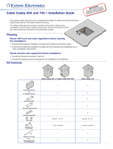
The Cable Cubby 1252 MS is a furniture-mounted enclosure for cable access,
connections, and AC power. The Cable Cubby 1252 MS provides the freedom to either
match the surface of the table or use a unique lid design that complements the room décor.
Unused cables can be stored out of the way while remaining connected to the presentation system.
NOTE: This product is intended for use only with Extron UL listed power modules (not included).
Planning
Check with local and state regulations before starting the installation
Ensure that the planned installation complies with national and local building and electrical codes.
Ensure that the planned installation complies with the Americans with Disabilities Act or other accessibility requirements.
Check all parts and equipment before installation
Ensure that all parts are present in the kit.
Ensure that necessary tools and equipment are available for the installation.
Kit Contents
Part Quantity Part Quantity
Connectivity bracket
1 Retractor pin and clip
1
#4-40 at head module
screws
4
#6-32 pan-head mounting
screws and star washers
8
AAP frame plate
1
#4 at head lid insert wood
screws
4
Cable grommet plate
1 Trim brackets
2
Hole plugs
6 (3/8"),
2 (1/4")
#8 pan head wood mounting
screws
12
Retractor bracket
1
ZipClip screws and washers
(for mounting of optional
ZipClip power supply)
2
Extron

2
Cable Cubby 1252 MS • Installation Guide (Continued)
Preparing the Table and Cable Cubby 1252 MS Lid
Prepare the lid and cut a hole in the surface where the enclosure will be installed. Read the following information before making a
cut.
Determine the best location for the enclosure
Ensure that the location where the Cable Cubby 1252 MS is to be installed is convenient for as many users as possible.
Ensure that the edge on which the lid opens is oriented correctly.
Ensure that there is ample space under the table for cables. Allow at least 36 inches of cable loop for each cable (see
Routing and Connecting Cables on page 10).
When installing retractors in the Cable Cubby, ensure that there is enough space for the retractor assembly under the table or
furniture (see the Dimensions with a Retractor on page 11 for retractor dimensions).
Prepare the table
ATTENTION:
• The correct dimensions for the cut in the table surface depend on the thickness of your lid material.
• If the total lid thickness is equal to or thicker than the table surface, see figure 1 on page 3.
• If total lid thickness is thinner than the table surface, see figure 2 on page 3.
•
Les dimensions corr
ectes pour la découpe dans la surface de table dépendent de l’épaisseur de votre couvercle :
• Si l’épaisseur totale du couvercle est égale ou plus importante que la surface de la table, regardez la
figure 1.
• Si l’épaisseur totale du couvercle est moins importante que la surface de la table, regardez la
figure 2.
•
For a pr
ofessionally-installed appearance, the mounting surface for the Cable Cubby 1252 MS requires precise cuts.
Extron strongly recommends cutting the hole via a computer numerical control (CNC) machine only.
• Pour offrir un design professionnel, il est nécessaire de couper avec précision la surface de montage du
Cable Cubby 1252 MS. Extron recommande vivement de percer le trou uniquement à l’aide d’une machine-outil à
commande numérique.
•
The opening in the table for the Cable Cubby should be cut only
by licensed and bonded craftspeople. Exercise care to
prevent scarring or damaging the furniture.
• L’ouverture dans la table pour le Cable Cubby doit être coupée uniquement par un ouvrier détenteur d’une licence.
Veillez à ne pas laisser de marques ni à détériorer le mobilier.

3
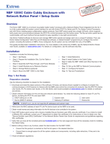
1. Cut a hole in the table for the Cable Cubby 1252 MS. See the table below to determine:
• The location and orientation of the cut on the table
• The correct size of the cut, based on the thickness of the table surface and the lid.
A Lid is thicker than or as thick as the table surface B Lid thickness is thinner than table surface
Extron
ExtronExtron
NOTE: A thinner lid requires a slightly larger cut
because the enclosure extends into the cut-out.
Figure 1. Thicker Lid Material Figure 2. Thinner Lid Material
SURFACE
CUT-OUT
AREA
Bottom View
Front (Width)
Rear (Width)
2.00"
(50.8 mm)
2.00"
(50.8 mm)
0.63"
(16.0 mm)
10.50"
(266.7 mm)
0.63"
(15.9 mm)
R= 0.25" (6.3 mm)
Cut Dimensions
Thicker table surface:
Width: 8.81 inches
(223.8 mm)
Depth: 5.25 inches
(133.3 mm)
Corner 0.25 inch
radius: (6.3 mm)
Cut Dimensions
Thinner table surface:
Width: 9.5 inches
(241.3 mm)
Depth: 5.25 inches
(133.3 mm)
Corner 0.25 inch
radius: (6.3 mm)
A B
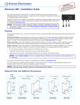
Figure 3. Enclosure Dimensions and Mounting Hole Locations
2.
Mark and pr
e-drill pilot holes, 1/8-inch in diameter,
8.56"
(217.4 mm)
4.43"
0.81"
(112.5 mm)
MAX
(20.6 mm)
(Varying thickness
)
0.2"
(5 mm)
Radius Corners
1/2-inch deep at the six mounting locations shown ( ) in
gure 3.
3. Fabricate the Cable Cubby lid to the dimensions shown
at right.
NOTE: Make the cut as accurate as possible, the
cutout piece can be used for the lid to be attached
to the Cable Cubby.

4
Cable Cubby 1252 MS • Installation Guide (Continued)
Preparing the Cable Cubby
Step 1 — Assemble Connectivity Modules
Connectivity modules allow you to populate the Cable Cubby enclosure with a combination of AAP modules, cable pass-through,
or retractors. Follow the steps below to assemble the connectivity modules of your choice.
Option 1: AAP module
Secure up to three single-space
AAP modules in the AAP frame
plate.
#4-40 Nut with
Captive Washer
Secure the AAP frame plate on the connectivity
brackets, using four of the provided #4-40 module
screws. Use a screwdriver to tighten the screws.
3
1
2
Insert cables through the bottom of the connectivity bracket.
Connect cables to the AAP modules.
NOTE: After assembling the module, proceed to Step 2 — Install the Modules on page 5.
Option 2: Cable pass-through module
Secure the grommet plate
on the connectivity bracket,
using four of the provided
#4-40 module screws. Use
a screwdriver to tighten the
screws.
Insert cables through the bottom
of the connectivity bracket and
into the holes of the grommet plate.
Snap the included
hole plugs into any
unused holes.
3
2
1
NOTE: After assembling the module, proceed to Step 2 — Install the Modules.

5
Option 3: Retractor Bracket
Use the retractor bracket to mount retractors in the Cable Cubby 1252 MS enclosure.
1
2
2
Extron
Extron
Secure the bracket using four of the
provided #6-32 pan-head mounting
screws with star washers.
Use a screwdriver to tighten the scr
ews.
Insert the bracket as shown.
The bracket may be installed on the left
or right side of the enclosure and at the
lowest height.
1
NOTES:
• After installing the bracket, proceed to “Step 2 — Install the Modules” to install the power module.
•
After mounting the Cable Cubby on the table, install the Retracto
rs (see Installing Retractors on page 8).
Step 2 — Install the Modules
Determine where the connectivity modules and power module will be installed in the Cable Cubby. The modules may be installed
on the left or right side of the enclosure and at various heights.
NOTE: Ensure that there is enough room above the modules for the Cable Cubby lid to close completely.
Extron
Extron
125V~ 12A MAX TOTAL
Secur
e the modules using four of the
provided #6-32 pan-head mounting
screws and star washers. Use a
screwdriver to tighten the screws
Insert the modules
into the Cable Cubby.
1
2
WARNING: Risk of Electric Shock. To ensure proper
electrical grounding, use the provided #6-32 mounting screws
with the star washers.
AVERTISSEMENT : Risque de choc électrique. An
d’assurer une mise à la terre correcte, utilisez les xations de
mise à la terre #6-32 et les rondelles en étoile fournies.

6
Cable Cubby 1252 MS • Installation Guide (Continued)
Step 3 — Mount the lid onto the Cable Cubby
If using screws,
perform
2
and
3
.
If NOT using screws,
perform
4
.
Option 2a: Mount lid
insert with screw
Mark and drill four
1/16-inch pilot holes.
Secur
e the lid onto the
Cable Cubby using #4
at head wood
screws.
— OR —
Option 2b: Mount the
fabricated lid without
screws
Secur
e the lid onto the
Cable Cubby using the
proper adhesive.
2
3
4
Align the lid to the Cable
Cubby. The back edge of
the lid lines up with the back
edge of the lid mechanism.
1
1
4
O
i
O
f
s
2
3
4
mechanis
m
.
Extron
Extron
2
3
Mounting the Cable Cubby in the Table
1. See the dimension on figure 3 on page 3 for the mounting hole locations OR have an assistant hold the Cable Cubby against
the underside of the mounting surface.
2. Install the screws in the two center pre-drilled mounting holes on each side, leaving 1/8 inch (4 mm) of the screw head
exposed.
3.
Use the two center slotted mounting holes on the mounting bracket to hang the Cable Cubby on the two installed scr
ews.
4. Snug the two screws just so that the Cable Cubby can still be moved on its slotted holes.
5.
Adjust the Cable Cubby position and alignment.
6.
Tighten the center mounting scr
ews while maintaining the position and alignment of the Cable Cubby.
7. Install the remaining mounting screws and secure the Cable Cubby to the table.

7
Step 1 — Perform height adjustment
NOTE: If the lid is the same thickness as the table, proceed to Step 2: Install trim brackets on page 8.
If the lid thickness is different than the table
thickness, loosen, but do not remove, the
wing bolts (two on each side), just enough
to allow the Cable Cubby to slide up and
down in the brackets.
Raise the unit up or down until the lid is ush with
the table top surface. Use an assistant if necessary.
1
Firmly tighten the wing bolts.
3
2
NOTE: If the lid is thinner than the table
surface, it may be necessary to relocate
the wing bolts to the bottom position of
the Cable Cubby.

8
Cable Cubby 1252 MS • Installation Guide (Continued)
Step 2 — Install trim brackets
If there is a gap, front and back, between the underside of the table and the Cable Cubby frame, install the trim brackets as follows:
Hold the trim bracket
against the underside of the
table, ush against the Cable
Cubby and centered on the unit.
Mark the three mounting holes.
Drill 1/8 inch (3 mm) diameter pilot holes,
1/2 inch (12.7 mm) deep.
Secure the trim bracket to the table using the
provided #8 wood screws.
Repeat through on the opposite of the Cable
Cubby.
2
3
4
1
1 3
Installing Optional Accessories
Installing Retractors
For horizontal or angular retractor mounting, see the information at right, then follow the steps below.
Insert the pin through the
Retractor mounting hole
on the side of the
Cable Cubby and
Retractor assembly.
Secure the clip
on the pin.
Insert Retractors into
the Retractor bracket.
Secure the locking screw
on each Retractor. Do not
overtighten.
2
1
4
3
Pin
Clip
Extron
Angular Mounting
Remove the enclosure screws as shown above, then follow
this step:
Horizontal Mounting
Cable Release
Assembly
Move the cable release assembly upward until
the angular mounting hole is visible. Reinstall the
enclosure screws in this hole (both sides).
Remove two enclosure screws
(one on each side) from this position.
Then, mount the Retractors as shown
at left.
Cable Release
Assembly
See the Cable Retractor Series Setup Guide, available on
the Extron website, for additional steps.
Remove two enclosure screws
(one on each side) from this position.
Then, mount the Retractors as shown
at left.
Move the cable release assembly upward until
the angular mounting hole is visible. Reinstall the
enclosure screws in this hole (both sides).

9
Installing an optional ZipClip 100 or ZipClip 200 mounting kit
ZipClip 100 mounts
horizontally with the
push tab to the right.
ZipClip 200 mounts
vertically on the bottommost
mounting location with the push tab up.
Cable Cubby 1252 MS
Use the provided ZipClip screws
and washers to mount the ZipClip
to the Cable Cubby 1252 MS.
1
Installing an optional PMK 155 Product Mounting Kit
PMK 155
Mount the device (up to 1.75 inch [44.4 mm] tall) and power supply to the PMK 155 (see the PMK 155 Installation Guide)
.
1
Install the two supplied Allen bolts from the
PMK 155 kit to the shelf leaving approximately
1/8 inch (4 mm) protruding.
2
Slide the shelf sideways horizontally onto the
Cable Cubby mounting bracket from the front
of the enclosure, on either the left or right side,
until the shelf drops into the slot in the bracket.
3
Tighten the bolts with a 4 mm Allen wrench.
4
5
Dress the cables associated with the device
installed on the shelf using tie wraps.
Connect cables to the system.
NOTE: The pipe clamp that is included with the PMK 155 is not
required for the Cable Cubby installation and can be discarded.
Side view with bracket

10
Cable Cubby 1252 MS • Installation Guide (Continued)
Routing and Connecting Cables
For cable pass-through applications,
allow at least 36 inches (0.9 m) of cable
loop for each cable.
Connect cables to the AV system
and connect the AC power cord.
Using zip ties, secure cables to the holes
on the bottom of the Cable Cubby.
1
2
3
1
Extron

11
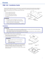
Dimensions with a Retractor
7.14"
(181.4 mm)
21.66"
(550.1 mm)
23.33"
(592.6 mm)
0.30"
(7.6 mm)
13.63"
(346.2 mm)
9.00"
(228.6 mm)
10.14"
(257.6 mm)
26.85"
(682.1 mm)
0.20"
(5.1 mm)
29.33"
(745.0 mm)
19.63"
(498.6 mm)
9.0"
(228.6 mm)
Figure 4. Retractor Dimensions with Cable Cubby 1252 MS

Cable Cubby 1252 MS • Installation Guide (Continued)
68-3289-01 Rev. B
12 19
© 2019 Extron Electronics — All rights reserved. www.extron.com All trademarks mentioned are the property of their respective owners.
Worldwide Headquarters: Extron USA West, 1025 E. Ball Road, Anaheim, CA 92805, 800.633.9876
For information on safety guidelines, regulatory compliances, EMI/EMF compatibility, accessibility, and related topics, see the
Extron Safety and Regulatory Compliance Guide on the Extron website.
Installation Checklist
Planning (page 1)
Check with local and state regulations before starting the installation
Check all parts and equipment before installation
Preparing the Table
Determine the best location for the enclosure
Determine cutout hole size based on lid thickness (page 3)
Cut the hole in the table and pre-drill mounting locations (page 3)
Fabricate Cable Cubby lid (page 3)
Preparing the Cable Cubby
Assemble Connectivity Modules (page 4)
Install the Modules (page 5)
Mount the Lid onto the Cable Cubby (page 6)
Mounting the Cable Cubby in the Table
Mount the Cable Cubby flush with the table (page 6)
If necessary, adjust the Cable Cubby height (page 7).
If necessary, install the trim brackets (page 8)
Installing optional equipment
Installing Retractors (page 8)
Installing a ZipClip mounting clip (page 9)
Installing a PMK 155 Product Mounting Kit (page 9)
Routing and Connecting Cables (page 10)
-
 1
1
-
 2
2
-
 3
3
-
 4
4
-
 5
5
-
 6
6
-
 7
7
-
 8
8
-
 9
9
-
 10
10
-
 11
11
-
 12
12


Extron electronics Cable Cubby 1252 MS User manual
- Type
- User manual
- This manual is also suitable for
Ask a question and I''ll find the answer in the document
Finding information in a document is now easier with AI
in other languages
Related papers
-
 Extron electronics Cable Cubby 1252 MS Owner's manual
-
 Extron electronics Cable Cubby 1202 User manual
-
 Extron electronics Cable Cubby 500 User manual
-
Extron electronics TLP Pro 720C User manual
-
 Extron electronics NBP 1200C User manual
-
 Extron electronics Retractor SM Series User manual
-
Extron electronics TLE 350 User manual
-
Extron electronics TouchLink TLP Pro 525C Series User manual
-
-
 Extron electronics PMK 155 User manual


Other documents
-
Extron Cable Cubby 100 User manual
-
-
Mircom LT-679 US-2000 Installation guide
-
-
-
-
Extron Cable Cubby 650 UT User manual
-
Extron Cable Cubby Series Connectivity Bracket Kits Owner's manual
-
-