Extron Cable Cubby 650 UT User manual

Type
User manual

Extron Cable Cubby 650 UT is an under-table mountable solution for cable access, connections, and AC power. It can be expanded for multiple users and applications, and is compatible with Extron AAPs, cable pass-through, and Retractors. The Cable Cubby 650 UT features a durable construction and a sleek design that blends seamlessly with any environment.

Extron Cable Cubby 650 UT is an under-table mountable solution for cable access, connections, and AC power. It can be expanded for multiple users and applications, and is compatible with Extron AAPs, cable pass-through, and Retractors. The Cable Cubby 650 UT features a durable construction and a sleek design that blends seamlessly with any environment.

1
IMPORTANT:
Go to www.extron.com for the
complete user guide
, installation
instructions, and specifications.
Cable Cubby 650 UT • Installation Guide
This guide provides instructions for an experienced technician to install and connect
the Extron Cable Cubby 650 UT.
The Cable Cubby 650 UT units are under furniture mountable and are expandable
for cable access, connections, and AC power.
NOTE: This product is intended for use only with Extron UL
listed power modules (not included). Go to www.extron.com for
recommended power modules.
Planning
Check with local and state regulations before starting the
installation
Ensure that the planned installation complies with national and local building and electrical codes.
Ensure that the planned installation complies with the Americans with Disabilities Act or other accessibility requirements.
Check all parts and equipment before installation
Ensure that all parts are present in each kit.
Ensure that necessary tools and equipment are available for the installation.
Kit Contents
125V~ 12A MAX TOTAL
Cable Cubby 650 UT
1
4
1
1
6 (3/8"), 2 (1/4")
1
1
4
#4-40 Module Screws
#6 Pan-head Mounting
Screws and Star Washers
AAP Frame Plate
Cable Grommet Plate
Hole Plugs
Retractor Pin & Clip
Connectivity Bracket
#4-40 Module Screws
AAP Frame Plate
Cable Grommet Plate
Hole Plugs
Retractor racket
Retractor Pin
& Clip
#6-32 Mounting screws and
Star Washers
2
Cable Cubby 650 UT • Installation Guide (Continued)
Preparing the Table
Cut a hole in the surface where the enclosure will be installed. The size of the hole depends on the number of enclosures used
(see Cut-out dimensions on the next page). Ensure the sides of the hole are smooth after cutting and nished before installing.
Read the following information before making a cut.
Determine the best location for the enclosure
Ensure that the location where the Cable Cubby is to be installed is convenient for as many users as possible.
Ensure that there is ample space under the table for cables. Allow at least 36 inches of cable loop for each cable (see
Routing and Connecting Cables on page7).
When installing Retractors in the Cable Cubby, ensure that there is enough space for the Retractor assembly under the table
or furniture.
NOTE:
To prevent objects from impeding cable retraction, allow at least 3 inches of clearance from the exposed cable side of
the enclosure (see the diagrams below).
Excess cabling may cause clearance issues. Use zip ties to secure under-table cabling to prevent accidental contact or
entanglement (see Routing and Connecting Cables).
22.95"
(583 mm)
26.47"
(672 mm)
21.28"
(540 mm)
12.23"
(311 mm)
9.23"
(234 mm)
30
30
Table Top
Series/2
Series/2
9.0"
(229 mm
)
15.14"
(385 mm)
21.14"
(537 mm)
Series/2 XL
Series/2 XL
3.0"
(76 mm)
3.0"
(76 mm)
28.95"
(735 mm)
3
Cut the hole in the table and pre-drill mounting holes
CAUTION: Wear safety glasses when operating power equipment. Failure to comply can result in eye injury.
ATTENTION : Portez des lunettes de sécurité lorsque vous utilisez l’équipement électrique. Ne pas respecter
cela peut conduire à une blessure à l’oeil.
ATTENTION: The opening in the table for the Cable Cubby should be cut only by licensed and bonded
craftspeople. Exercise care to prevent scarring or damaging the furniture.
ATTENTION : L’ouverture dans la table pour le Cable Cubby devrait être coupée seulement par des artisans
autorisés et qualiés. Faites attention à ne pas faire de marques sur le meuble et à ne pas l’endommager.
Cut-out dimensions
For one or two enclosures, the cut-out dimensions and mounting hole locations are shown below. For more enclosures, multiply
the length accordingly. If necessary, pre-drill into the furniture at the keyhole and mounting hole locations.
10"
(254 mm)
SURFACE
CUT-OUT
AREA
1
/
16
(1.5 mm)
4
1
/
4
"
(108 mm)
+
-
11.5"
(292 mm)
12"
(305 mm)
5"
(127 mm)
SURFACE
CUT-OUT
AREA
1
/
16
(1.5 mm)
4 1/4"
(108 mm)
+
-
1.5"
(38 mm)
(178 mm)
1.5"
(38 mm)
3"
(76 mm)
6"
(152 mm)
6.5"
(165 mm)
6.5"
(165 mm)
Mounting Holes (8)
6"
(152 mm)
6.5"
)
3"
(76 mm)
1.5"
(38 mm)
1.5"
(38 mm)
Keyholes (4)
Keyholes (2)
2.0"
(51 mm)
NOTE: Diagrams shown above are not drawn to scale.
Dimensions and cut-out templates are available online at www.extron.com.
4
Cable Cubby 650 UT • Installation Guide (Continued)
Preparing the Cable Cubby
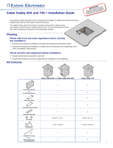
Step 1 (Only for multiple enclosures) — Assemble Enclosures
Repeat steps 1 and 2 to
add more enclosures to
the extension.
Before attaching the enclosur
e,
ensure the keyhole mounting
holes are orientated in the
same direction.
Attach the enclosures together
with the four pan-head
mounting screws and washers
that were removed in step 1.
Using a #2 screw driver,
unscrew the four pan-head
screws that attach the enclosure
sides of the Cable Cubby together.
Repeat this step on the corresponding
side of the other enclosure.
Detach side panels of both enclosures.
11
2
2
3
3
2
3
1
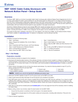
Step 2 — Assemble Connectivity Modules
Connectivity modules allow you to populate the Cable Cubby enclosure with a combination of AAPs, cable pass-through, or
Retractors. Follow the steps below to assemble the connectivity modules of your choice.
Option 1: AAP Module
Secure up to three single-space
AAPs in the AAP plate.
Secure the AAP plate on the connectivity brackets,
using four of the provided module screws.
#4-40 Nut with
Captive Washer
Insert cables through the bottom of the connectivity bracket.
Connect cables to the AAPs.
1
3
2
Option 2: Cable Pass-Through Module
Secure the grommet
plate on the connectivity
bracket using four of the
provided module screws.
Insert cables through
the bottom of the connectivity
bracket and into the holes of
the grommet plate.
Snap the included
hole plugs into any
unused holes.
3
2
1
Option 3: Retractor Bracket
Secure the bracket using four of
the provided pan-head mounting
screws with star washers. Tighten
the screws using a screwdriver.
2
Insert the bracket as shown.
The bracket may be installed on the left
or right side of the enclosure and at the
lowest height.
1
NOTE: The opening of the
bracket should be installed
towards the outside of the
enclosure.
5
Step 3 — Install the Modules
Determine where the connectivity modules and/or power module will be installed in the Cable Cubby. The modules may be
installed on the left or right side of the enclosure and at various heights.
For the Power module:
WARNING: Risk of Electric Shock. To
ensure proper electrical grounding, use the
provided #6-32 mounting screws with the star
washers.
AVERTISSEMENT : Risque de choc
électrique. An d’assurer une mise à la terre
correcte, utilisez les xations de mise à la terre
#6-32 et les rondelles en étoile fournies.
125V~ 12A MAX TOTAL
Secure the modules
using four of the provided
pan-head mounting screws
and star washers.
2
Insert the modules
into the Cable Cubby.
1
Mounting the Cable Cubby in the Table
Align the enclosure with the pre-drilled holes under the furniture. Secure the enclosure with the appropriate screws (see Cut the
hole in the table and pre-drill mounting holes on page3).
125V~ 12A MAX TOTAL
125V~ 12A MAX TOTAL
2
Hook the Cable Cubby assembly
onto the screws, as shown at right.
Slide the Cable Cubby assembly
into slot.
Tighten the screws to secure
the Cable Cubby assembly.
Insert a mounting screw (provided) into each
of the two holes. Tighten each screw until it
protrudes 1/4 inch from the bottom of the table.
1
3
Drill pilot holes through the clearance
openings on the Cable Cubby. Insert and
tighten mounting screws (provided).
Clearance
Opening
6
Cable Cubby 650 UT • Installation Guide (Continued)
Installing Retractors
Follow the steps below to install Retractors. Before installing the Retractors, adjust the Retractors for horizontal or angular
mounting, see the information below, then follow the installation steps below.
Horizontal Mounting
Remove two enclosure screws
(one on each side) from this position.
Then, mount the Retractors as shown
below.
Cable Release
Assembly
Move the cable release assembly upward until
the angular mounting hole is visible. Reinstall the
enclosure screws in this hole (both sides).
See the Cable Retractor Series/2 Setup Guide, available on the
Extron website, for additional steps.
Angular Mounting
Remove the enclosure screws as shown on the left, then follow this
step:
Remove two enclosure screws
(one on each side) from this position.
Then, mount the Retractors as shown
below.
Cable Release
Assembly
Move the cable release assembly upward until
the angular mounting hole is visible. Reinstall the
enclosure screws in this hole (both sides).
NOTE: Extron recommends mounting the Retractor bracket so the release buttons for the Retractor are against the wall of
the enclosure, to ensure adequate clearance below the Cable Cubby.
Insert the pin thr
ough the
Retractor mounting hole on
the side of the Cable Cubby
and Retractor assembly
.
Secure the clip
on the pin.
Insert Retractors into
the Retractor bracket.
Secure the locking screw
on each Retractor. Do not
overtighten.
2
3
1
4
7
Step 2 — Under the table, adjust the side clamps on the enclosure
Alternative Retractor Configuration for Cable Cubby 650 UT
Optional Double Retractor bracket mounting:
Install brackets as shown below. Two double Retractor brackets can mount up to four Retractors.
NOTE: Mount the Double Retractor bracket with the release buttons for the Retractor against the wall of the enclosure,
opposite from each other, as shown below. DO NOT mount the Double Retractor bracket side by side. There is not enough
space to insert the mounting pins side by side.
Side View
E
E
Top View
Secure the brackets using
four of the provided pan-head
mounting screws with star
washers. Tighten the screws
using a screwdriver.
Insert the brackets as shown.
The bracket may be installed
on the left or right side of the
enclosure and at the lowest height.
2
1
.
Routing and Connecting Cables
For cable pass-through applications,
allow at least 36 inches (0.9 m) of cable
loop for each cable.
Connect cables to the AV system
and connect the AC power cord.
Using zip ties, secure cables to the holes
on the bottom of the Cable Cubby.
1
2
3
NOTE: Ensure that there is no tension on the power cable.
CAUTION:
Risk of Electric Shock.
This equipment must be grounded.
ATTENTION :
Risque de choc électrique.
Cet équipement doit être xé au sol.
NOTE: Mount Retractors opposite each other (see
images above).
8
68-3062-50 Rev. B
08 18
For information on safety guidelines, regulatory compliances, EMI/EMF compatibility, accessibility, and related topics, see the
Extron Safety and Regulatory Compliance Guide on the Extron website.
© 2017-2018 Extron Electronics — All rights reserved. www.extron.com
All trademarks mentioned are the property of their respective owners.
Installation Checklist
Planning (page1)
Check with local and state regulations before starting the installation
Check all parts and equipment before installation
Determine number of enclosures to install
Preparing the Table (page2)
Determine the best location for the enclosure
Verify sufcient space under furniture
Cut a hole in the table and pre-drill mounting holes (page 3)
Preparing the Cable Cubby (page4)
If applicable, assemble enclosures
Assemble connectivity modules
Install the modules (page 5)
Mounting the Cable Cubby in the Table (page5)
Mount the Cable Cubby under the table
Installing Retractors (page6)
Remove Retractor screws for horizontal and angular mount applications
Install Retractors into the bracket
Routing and Connecting Cables (page7)
Dress cables under the table
Connect cables to the AV system
  • Page 1 1
  • Page 2 2
  • Page 3 3
  • Page 4 4
  • Page 5 5
  • Page 6 6
  • Page 7 7
  • Page 8 8

Extron Cable Cubby 650 UT User manual

Type
User manual

Extron Cable Cubby 650 UT is an under-table mountable solution for cable access, connections, and AC power. It can be expanded for multiple users and applications, and is compatible with Extron AAPs, cable pass-through, and Retractors. The Cable Cubby 650 UT features a durable construction and a sleek design that blends seamlessly with any environment.

Ask a question and I''ll find the answer in the document

Finding information in a document is now easier with AI

in other languages