Page is loading ...

1
READ THROUGH THIS MANUAL
BEFORE STARTING CONSTRUCTION.
IT CONTAINS IMPORTANT INSTRUCTIONS
AND WARNINGS CONCERNING THE
ASSEMBLY AND USE OF THIS MODEL.
WEIGHT
60–65 oz [1700 –1842g]
WING LOADING
20.3 –22.1 oz/ft
2
[61.9– 67.4 g/dm
2
]
RADIO
4-Channel required
Tower
Hobbies
®
guarantees
this kit to be
free from defects
in both material and
workmanship at the
date of purchase. This
warranty does not cover any
component parts damaged by
use or modication. In no case shall
Tower Hobbies’ liability exceed the
original cost of the purchased kit. Further,
Tower Hobbies reserves the right to change
or modify this warranty without notice.
In that Tower Hobbies has no control over the nal
assembly or material used for nal assembly, no
liability shall be assumed nor accepted for any damage
resulting from the use by the user of the nal user-assembled
product. By the act of using the user-assembled product, the
user accepts all resulting liability.
If the buyer is not prepared to accept the liability associated with the
use of this product, the buyer is advised to return this kit immediately in
new and unused condition to the place of purchase.
To make a warranty claim send the defective part or item to Hobby Services at
the address below:
Hobby Services • 3002 N. Apollo Dr. Suite 1 • Champaign IL 61822 • USA
Include a letter stating your name, return shipping address, as much contact information as
possible (daytime telephone number, fax number, e-mail address), a detailed description of
the problem and a photocopy of the purchase receipt. Upon receipt of the package the problem
will be evaluated as quickly as possible.
WARRANTY
TOWA2090© 2017 Tower Hobbies.
®
A subsidiary of Hobbico, Inc.
®
®
TOWER HOBBIES
Champaign, Illinois
(217) 398-8970 ext. 6
WINGSPAN
53 in [1346mm]
WING AREA
424 sq in [27.35 dm
2
]
LENGTH
40 in [1016 mm]
airsupport@hobbico.com
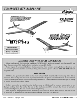
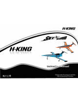
INSTRUCTION
MANUAL

2
As a new owner of an unmanned aircraft system (UAS), you
are responsible for the operation of this vehicle and the safety
of those around you. Please contact your local authorities
to nd out the latest rules and regulations.
In the United States, please visit:
knowbeforeyou y.org faa.gov/uas
AMA
We urge you to join the AMA (Academy of Model Aeronautics)
and a local R/C club. The AMA is the governing body of model
aviation and membership is required to y at AMA clubs.
Though joining the AMA provides many bene ts, one of the
primary reasons to join is liability protection. Coverage is not
limited to ying at contests or on the club eld. It even applies
to ying at public demonstrations and air shows. Failure
to comply with the Safety Code may endanger insurance
coverage. Additionally, training programs and instructors are
available at AMA club sites to help you get started the right
way. There are over 2,500 AMA chartered clubs across the
country. Contact the AMA at the address or toll-free phone
number below.
Academy of Model Aeronautics
5151 East Memorial Drive
Muncie, IN 47302-9252
Tele. (800) 435-9262
Fax (765) 741-0057
Or via the Internet at: www.modelaircraft.org
IMPORTANT: Two of the most important things you can do
to preserve the radio controlled aircraft hobby are to avoid
ying near full-scale aircraft and avoid ying near or over
groups of people.
SAFETY PRECAUTIONS
Protect Your Model, Yourself & Others…
Follow These Important Safety Precautions
1. Your Ryan STA EP ARF should not be considered a toy, but
rather a sophisticated, working model that functions very
much like a full-size airplane. Because of its performance
capabilities, this model, if not assembled and operated
correctly, could possibly cause injury to yourself or
spectators and damage to property.
2. You must assemble the model according to the instructions.
Do not alter or modify the model, as doing so may result in
an unsafe or un yable model. In a few cases the instructions
may differ slightly from the photos. In those instances the
written instructions should be considered as correct.
3. You must take time to build straight, true and strong.
4. You must use an R/C radio system that is in rst-class
condition.
5. You must correctly install all R/C and other components
so that the model operates correctly on the ground and in
the air.
6. You must check the operation of the model before every
ight to insure that all equipment is operating and that the
model has remained structurally sound. Be sure to check
clevises or other connectors often and replace them if they
show any signs of wear or fatigue.
7. If you are not an experienced pilot or have not own this
type of model before, we recommend that you get the
assistance of an experienced pilot in your R/C club for
your rst ights. If you’re not a member of a club, your
local hobby shop has information about clubs in your area
whose membership includes experienced pilots.
8. While this ARF has been ight tested to exceed normal
use, if a motor larger than the one recommended is used,
TABLE OF CONTENTS
AMA . . . . . . . . . . . . . . . . . . . . . . . . . . . . . . . . . . . . . . . . . . 2
SAFETY PRECAUTIONS . . . . . . . . . . . . . . . . . . . . . . . . . 2
REQUIRED ITEMS . . . . . . . . . . . . . . . . . . . . . . . . . . . . . . 3
Radio Components . . . . . . . . . . . . . . . . . . . . . . . . . . . 3
Battery and Charger . . . . . . . . . . . . . . . . . . . . . . . . . . 3
Adhesives and Building Supplies . . . . . . . . . . . . . . . . 3
Optional Supplies and Tools . . . . . . . . . . . . . . . . . . . . 3
CONTENTS . . . . . . . . . . . . . . . . . . . . . . . . . . . . . . . . . . . . 4
ORDERING REPLACEMENT PARTS . . . . . . . . . . . . . . . 4
KIT INSPECTION . . . . . . . . . . . . . . . . . . . . . . . . . . . . . . . 4
PREPARATION . . . . . . . . . . . . . . . . . . . . . . . . . . . . . . . . . 5
WING ASSEMBLY. . . . . . . . . . . . . . . . . . . . . . . . . . . . . . . 5
Join the Wing Panels . . . . . . . . . . . . . . . . . . . . . . . . . . 8
Install the Landing Gear. . . . . . . . . . . . . . . . . . . . . . . . 8
ASSEMBLE THE FUSELAGE. . . . . . . . . . . . . . . . . . . . . 12
Rudder & Elevator Servo Installation. . . . . . . . . . . . . 14
Install the Motor and ESC . . . . . . . . . . . . . . . . . . . . . 16
Finish Assembly. . . . . . . . . . . . . . . . . . . . . . . . . . . . . 17
Apply the Decals . . . . . . . . . . . . . . . . . . . . . . . . . . . . 18
GET THE MODEL READY TO FLY. . . . . . . . . . . . . . . . . 19
Check the Control Directions . . . . . . . . . . . . . . . . . . 19
Set the Control Throws . . . . . . . . . . . . . . . . . . . . . . . 19
Balance the Model Laterally . . . . . . . . . . . . . . . . . . . 20
Balance the Model (C.G.). . . . . . . . . . . . . . . . . . . . . . 20
PREFLIGHT . . . . . . . . . . . . . . . . . . . . . . . . . . . . . . . . . . . 21
Identify Your Model . . . . . . . . . . . . . . . . . . . . . . . . . . 21
Charge the Batteries . . . . . . . . . . . . . . . . . . . . . . . . . 21
Ground Check and Range Check . . . . . . . . . . . . . . . 21
SAFETY PRECAUTIONS . . . . . . . . . . . . . . . . . . . . . . . . 21
FLYING. . . . . . . . . . . . . . . . . . . . . . . . . . . . . . . . . . . . . . . 22
Takeoff . . . . . . . . . . . . . . . . . . . . . . . . . . . . . . . . . . . . 22
Flight . . . . . . . . . . . . . . . . . . . . . . . . . . . . . . . . . . . . . 23
Landing . . . . . . . . . . . . . . . . . . . . . . . . . . . . . . . . . . . 23

3
the modeler is responsible for taking steps to reinforce
the high stress points and/or substituting hardware more
suitable for the increased stress.
9. WARNING: The cowl and wheel pants included in this kit
are made of berglass, the bers of which may cause eye,
skin and respiratory tract irritation. Never blow into a part
to remove berglass dust, as the dust will blow back into
your eyes. Always wear safety goggles, a particle mask and
rubber gloves when grinding, drilling and sanding berglass
parts. Vacuum the parts and the work area thoroughly after
working with berglass parts.
We, as the ARF manufacturer, provide you with a top quality,
thoroughly tested plane and instructions, but ultimately
the quality and yability of your nished model depends
on how you build it; therefore, we cannot in any way
guarantee the performance of your completed model,
and no representations are expressed or implied as to the
performance or safety of your completed model.
REMEMBER: Take your time and follow the instructions
to end up with a well-built model that is straight and true.
REQUIRED ITEMS
Radio Components
A transmitter and receiver with 4-channels is required. The
Tactic TTX650 6-channel or Futaba 6J 6-channel radio system
are great low-cost radio systems perfect for the Ryan STA
EP ARF.
❍ (1) Transmitter Futaba 6J 6-channel S-FHSS (FUTK6000)
or Tactic TTX650 6-channel SLT (TACJ2650)
❍ (1) FUTL7627 Futaba R617FS 7-Channel FASST
Receiver
❍ (4) Servos Futaba S3150 Slim Digital Servo (FUTM0303)
or Hitec HS-81 Standard Mini Servo (HRCM3402)
❍ (2) Futaba 9” (229mm) Servo Extension (FUTM3910)
or Tactic 12” (305mm) Servo Extension (TACM2130)
❍ (1) Y-Harness FUTM4135 or TACM2751
❍ (1) Motor RimFire .32 (42-50-800) (GPMG4700)
❍ (1) Speed Control Castle Creations Phoenix Edge Lite
75 (CSEM1200)
❍ (1) 4mm Female Connector (3) (GPMM3115)
❍ (1) Male Star Connector (HCAM4010)
❍ (1) 1” x 6” Velcro (for addition battery packs) (GPMQ4480)
Propellers
❍ 13x8E Propeller (APCQ3080)
❍ 14x8.5 Propeller (APCQ4011)
Battery and Charger
A 3S 3200mAh – 3600 mAh LiPo battery is required to power
the Ryan STA EP ARF.
❍ Great Planes ElectriFly LiPo 3S 11.1V 3200mAh 25C
Star Plug (GPMP0871)
❍ FlightPower LiPo FP50 3S 11.1V 3600 mAh 50C Star
Plug (FPWP5363)
Most modelers may already have a suitable LiPo charger,
but for those that do not, the Duratrax Onyx 235 AC/DC
Advanced Peak Charger (DTXP4235) is one of the chargers
recommended. The Onyx charger is perfect for 3S batteries
used with the Ryan STA EP ARF and may be powered either
by an external DC power source (such as a 12V battery), or
a 110V AC outlet. The Onyx also has an adjustable charge
rate to charge your batteries in as little as a half-hour or
less (depending on the condition of your batteries and the
manufacturer’s speci ed charge rate). The Onyx can also
charge large batteries and batteries other than LiPo. So it is a
versatile charger you can grow into. The 235 also has an LCD
digital display screen, so you can see how much capacity
it took to recharge the battery (required for monitoring the
condition of your batteries and calculating how long your
plane can y).
Adhesives and Building Supplies
❍ Tower Hobbies 6-minute Epoxy (TOWR3806)
❍ Tower Hobbies 30-minute Epoxy (TOWR3810)
❍ Mixing Sticks (50, GPMR8055)
❍ Mixing Cups (GPMR8056)
❍ Epoxy Brushes (GPMR8060)
❍ Tower Hobbies Build-It CA Thin Glue (TOWR3800)
❍ Denatured Alcohol (for epoxy clean-up)
❍ Masking Tape
❍ #64 Rubber Bands (HCAQ2020)
❍ 1/16" [1.5mm], 5/64" [2mm], 3/32" [2.5mm] drill bits
❍ Drill
❍ Phillips head screwdriver
❍ Wire Cutters
❍ Pliers
❍ Stick-on segmented weights (GPMQ4485)
❍ Medium T-pins (HCAR5150)
❍ CG Machine (GPMR2400)
❍ Paper Towels
❍ #1 Hobby Knife (RMXR6903)
❍ #11 Blades (5-pack, RMXR6930)
Covering tools
❍ Top Flite MonoKote Sealing Iron (TOPR2100)
❍ Top Flite Hot Sock Iron Cover (TOPR2175)
❍ Top Flite MonoKote Trim Seal Iron (TOPR2200)
❍ Top Flite MonoKote Heat Gun (TOPR2000)
❍ Coverite 21
st
Century Sealing Iron (COVR2700)
❍ Coverite 21
st
Century Cover Sock (COVR2702)
❍ Coverite 21
st
Century Trim Sealing Iron (COVR2750)
Optional Supplies and Tools
Here is a list of optional tools mentioned in the manual that
will help you build the Ryan STA EP ARF.
❍ CA Applicator Tips (HCAR3780)
❍ CA Debonder (GPMR6039)
❍ Robart Super Stand II (ROBP1402)
❍ Servo Horn Drill (HCAR0698)
❍ AccuThrow De ection Gauge (GPMR2405)
❍ Precision Magnetic Prop Balancer (TOPQ5700)

4
ORDERING REPLACEMENT PARTS
Replacement parts are available from Tower Hobbies for your
Ryan STA EP ARF. Our order assistance representatives are
ready to answer your questions or to place your order. Call
us at (800) 637-6050.
Order No. Description
Wing
Fuselage
Tail Surfaces
Cowl
Hatch
Landing Gear Set
Plastic Parts Set
Tail Wheel Assembly
Decals
TOWA5015
TOWA5016
TOWA5017
TOWA5018
TOWA5019
TOWA5020
TOWA5021
TOWA5022
TOWA5023
Order No. Description
Belly Pan
Wheel Pants
Spinner
Wing Bolts (2)
TOWA5024
TOWA5025
TOWA5026
TOWA4077
KIT INSPECTION
If any parts are missing or damaged, consult Tower Hobbies
Order Assistance. (See phone numbers below.)
Note: All parts are one per kit unless otherwise stated.
Toll Free Order Assistance . . . . .800 637-6050
Fax Ordering . . . . . . . . . . . . . . . .217 398-7721
E-mail: airsupport@towerhobbies.com
CONTENTS
1. Cowl
2. Fuselage
3. Belly Pan
4. Plywood Wing
Joiners (2)
5. Right Wing Half
6. Left Wing Half
7. Fin
8. Rudder
9. Left Landing Gear
Cover Top
10. Left Wheel Pant
11. Right Landing Gear
Cover Top
12. Right Wheel Pant
13. Left Landing Gear Wire
14. Right Landing
Gear Wire
15. Main Wheels (2)
16. Tail Gear Wire
17. Tail Wheel
18. Wind Screen
19. Head Rest
20. Spinner
21. Horizontal Stabilizer
22. Left Elevator
23. Right Elevator
24. Elevator Joiner Wire
1
4
7
2
5
8
3
6
9
10
11
12
1314
15
16
17
18
19
20
21
22 23
24

5
PREPARATION
Use a covering iron set to about 300° F with a covering sock
to go over the model tightening the covering where necessary.
NOTE: This covering material requires less heat than you
may be used to. Excessive heat will cause the covering to pull
away from the seams or may even cause the parts to bend.
WING ASSEMBLY
Let’s start with the right wing.
❏
1. Pull on the ailerons to check that the CA hinges are
securely glued. If needed, apply a couple drops of thin CA
and check again.
❏
2. Follow the instructions included with your servos to
install the rubber grommets and metal eyelets.
❏
3. Install a servo lead extension (not included). Secure the
connection with tape or shrink tubing (not included).
❏
4. Center the aileron servo.
a. Connect the servo to the receiver.
b. Switch on the transmitter and temporarily connect
the ESC and motor battery or a receiver battery to
the receiver.
c. Center the aileron trim on the transmitter.
d. Install a servo arm so that one of the arms is
perpendicular to the centerline of the servo, as shown.
Remove the unused arms.
e. Unplug the motor or receiver battery and switch off
the transmitter.
❏
5. Center the aileron servo arm in the aileron hatch opening.
Use 6-minute epoxy to glue the two hardwood aileron servo
mounting blocks to the hatch.
❏
6. Place a piece of thin cardboard or paper folded over
several times between the servo and the aileron hatch. Drill
1/16" [1.5mm] holes for the servo mounting screws and install
the screws.

6
❏
7. Remove the servo mounting screws and servo and
apply a drop of thin CA in each hole to harden the threads
in the wood blocks.
❏
8. After the CA has cured, reinstall the aileron servo
and screws.
❏
9. Tie the string from inside the wing to the end of the
aileron servo wire. Wrapping a piece of masking tape around
the end of the servo wire and the string will help when pulling
the servo wire through the wing.
❏
10. Pull the servo wire through the wing and route the wire
out of the hole in the top of the wing.
❏
11. Mount the aileron servo hatch to the wing with four
2x10mm sheet metal screws and 2mm at washers. After
installing the screws, remove the screws and hatch. Then,
harden the screw holes with thin CA. After the CA cures,
reinstall the screws and hatch.
❏
12. Thread a nylon clevis 20 turns onto the 2-56 x 4-3/8"
[110 mm] metal pushrod. Slide a silicone clevis retainer over
the clevis.
❏
13. Attach the clevis in the middle hole of the nylon
control horn.

7
❏
14. Position the control horn on the aileron so that the
pushrod is aligned with the aileron servo arm and the holes
in the control horn are aligned with the aileron hinge line.
Mark the two control horn mounting holes.
❏
15. Drill 1/16" [1.5mm] holes at the marks. Do not drill
completely through the wing.
❏
16. Mount the control horn to the aileron with two 2x10mm
sheet metal screws.
❏
17. Remove the screws and control horn and harden the
screw holes with thin CA. Once the CA has cured, reinstall
the control horn.
❏
18. Switch on the transmitter and receiver. Make sure the
aileron servo arm and aileron are centered. Mark the pushrod
where it crosses the outer hole of the aileron servo arm.
❏
19. Make a 90 degree bend at the mark. Trim off the end
of the pushrod ¼" [6.5mm] from the bend.
❏
20. Insert the pushrod and secure it with a nylon Faslink.
Slide the silicone clevis retainer over the clevis.

8
❏
21. Use 6-minute epoxy to glue the nylon wing dowel in
the leading edge of the wing.
Return to step 1 and install the aileron servo in the left wing.
Join the Wing Panels
❏
1. Use 6-minute epoxy to glue the two plywood wing
joiners together.
❏
2. Without glue, insert the plywood wing joiner in one wing
half and test t the wing halves together to check the t. Make
sure both wing halves t together at the root without any
gaps. If needed, slightly sand the wing joiner for the best t.
❏
3. Gather everything needed to glue the two wing halves
together including 30-minute epoxy, mixing sticks, mixing
cup, epoxy brush, rubberbands, masking tape, 12" [305mm]
long wire or small diameter dowel, denatured alcohol, paper
towels and the two ¼-20 wing bolts from the parts bag.
❏
4. Mix 2 oz. [59.1cc] of 30-minute epoxy. Working quickly,
pour a generous amount into the joiner pocket of one wing
half. Use the wire or dowel to thoroughly distribute the epoxy,
coating all surfaces inside the joiner pocket. Coat the root rib
and one half of the wing joiner. Insert the wing joiner in the
wing. Coat the joiner pocket in the other wing half and the
other end of the wing joiner. Join the wing halves together.
Use the rubberbands to hold the trailing edges of the wing
together using the wing bolts and leading edge dowels.
Stand the wing up on end and use paper towels dampened
with denatured alcohol to remove the excess epoxy that
squeezes out. Use masking tape to hold the wing halves in
alignment if necessary.
❏
5. After the epoxy cures, remove the rubberbands and
masking tape.
Install the Landing Gear
❏
1. Trim the covering from over the slots for the right main
landing gear.

9
❏
2. Insert the main landing gear wire into the slots. Make
sure the wire is completely seated in the slots.
❏
3. Position the nylon at straps over the landing gear wire
and drill 1/16" [1.5mm] pilot holes in the hardwood rails. Don’t
drill through the top of the wing.
❏
4. Secure the at straps to the wing with 2x10mm sheet
metal screws and 2mm at washers. Remove the screws
and harden the threads in the wood with thin CA. Reinstall
the screws.
❏
5. Look at the upper landing gear covers from the front
to determine the left and right covers.
❏
6. Temporarily slide the upper gear cover over the main
landing gear.

10
❏
7. Slide the right wheel pant over the right landing gear.
Slide the wheel pant down and position it so that the landing
gear is as far forward as possible. Then, rotate the wheel
pants into position.
❏
8. Slide the upper gear cover over the wheel pant and slide
the wheel pant down so that the axle is exposed.
❏
9. Apply a drop of thread locker to a 3mm set screw. Install
the set screw in a 4mm wheel collar. Slide the wheel collar
on the axle and tighten the set screw.
❏
10. Slide the main wheel on the axle and secure it with a
second 4mm wheel collar and 3mm set screw.

11
❏
11. Position the wheel pant so that the wheel collars are
inside the pant and the wheel is centered. Center the upper
gear cover.
❏
12. Mark and trim the upper gear cover to clear the
screw heads.
❏
13. Drill 1/16" [1.5mm] pilot holes through the front and
back of the upper gear cover and into the hard wood gear
rails. Secure the upper gear cover to the wing with 2x10mm
sheet metal screws. As before, use thin CA to harden the
threads in the wood rails.
❏
14. Position a nylon strap in the recess and mark the
hole locations.
❏
15. Drill a 5/64" [2mm] hole through the wheel pants at
the marks, perpendicular to the recess.
❏
16. Secure the wheel pants to the landing gear with the
nylon strap, 2x10mm machine screw, 2mm at washer and
2mm nut. Apply a drop of thread locker to the threads of the
screw before installing the 2mm nut. Do not over-tighten the
screws, crushing the berglass wheel pant.
17. Return to step 1 and install the left main landing gear
and wheel pants.

12
ASSEMBLE THE FUSELAGE
❏
1. Install the wing on the fuselage and secure it with the
10- 24 x 2" [51mm] nylon wing bolts.
❏
2. Slide the horizontal stabilizer into the fuselage. Insert
the vertical n to position the horizontal stabilizer.
❏
3. Check that the horizontal stabilizer is parallel with the
wing. If it is not, lightly sand the stabilizer slot until it is parallel.
❏
4. IMPORTANT: Insert the elevator joiner wire in the
stabilizer slot. Then, use 30-minute epoxy to glue the stabilizer
in the fuselage. Use the vertical n to temporarily position
the stabilizer. Wipe off any excess epoxy with a paper towel
and denatured alcohol.
❏
5. Use epoxy to glue the n in. Make sure it is perpendicular
to the horizontal stabilizer.
❏
6. Insert a T-pin into the center of six CA hinges.
❏
7. Insert the hinges into the trailing edge of the horizontal
stabilizer, up to the T-pin.
❏
8. Test t the elevators to the horizontal stabilizer.
❏
9. Remove the elevators and clean the elevator joiner wire
with denatured alcohol. Apply 6-minute epoxy in the joiner
wire holes in the elevators and reinstall the elevators on the
stabilizer. Remove the T-pins and apply 5 drops of thin CA
to both sides of each CA hinge.

13
❏
10. Apply a dab of grease or oil to prevent epoxy
from adhering.
❏
11. Insert the tail gear wire in the aft end of the fuselage.
Use the T-pin method to temporarily insert the three CA
hinges in the n. Test t the rudder on the n.
❏
12. Remove the rudder and note the position of the nylon
tail gear bearing in the fuselage. Glue the tail gear bearing
in the fuselage with 6-minute epoxy.
❏
13. Once the epoxy cures, glue the rudder to the n using
the same method used to attach the elevators.
❏
14. Insert the rudder control horn in the slot on the left
side of the rudder. Mark the control horn at the joint between
the control horn and the rudder.
❏
15. Use sandpaper to sand off the paint below the line.
❏
16. Glue the rudder control horn in the rudder using
6-minute epoxy.
❏
17. Slide the tail wheel on the tail gear axle. Apply a drop
of thread-locker to a 3mm set screw. Thread the set screw
into a 2mm wheel collar and install it on the tail gear.

14
Rudder & Elevator Servo Installation
❏
1. Install the grommets on the rudder and elevator servos.
❏
2. Connect the rudder and elevator servos to the receiver.
Switch on the transmitter and receiver. Center the rudder and
elevator trims. Install and position the servo arms as shown.
Trim off the excess arms.
❏
3. Insert the 2-56 x 24" [610mm] metal pushrods in the
rudder and elevator pushrod tubes. Position the rudder and
elevator servos so that the pushrods align with the servo arm.
❏
4. Secure the servos in the servo tray using the screws
provided with the servos. Use thin CA to harden the threads
in the plywood servo tray.
❏
5. Use adhesive backed hook and loop material to
attach the receiver to the bottom of the servo/battery
tray. Route the receiver antennas following the radio
manufacturer’s instructions.
❏
6. Trim off the end of one of the nylon clevises as shown.
❏
7. Thread the nylon clevis 20 turns onto one of the 24"
[610mm] metal pushrods. Slide a clevis retainer onto the clevis.
❏
8. Insert the pushrod into the rudder pushrod tube. Attach
the clevis to the rudder control horn and slide the clevis
retainer over the clevis.
❏
9. Switch on the transmitter and receiver. Center the
rudder and mark the rudder pushrod where it crosses the
rudder servo arm.

15
❏
10. Make an L-bend at the mark, trim off the excess pushrod
and attach the pushrod to the rudder servo with a Faslink.
❏
11. Thread the last nylon clevis, 20 turns onto the second
24" [610mm] metal pushrods. Slide a clevis retainer onto
the clevis.
❏
12. Insert the pushrod into the elevator pushrod tube.
Attach a nylon control horn to the clevis as shown.
❏
13. Position the control horn on the elevator so that the
holes in the control horn are aligned with the elevator hinge
line. Also make sure the control horn is positioned over the
elevator joiner wire inside the elevator. Mark the two control
horn mounting holes.
❏
14. Drill 3/32" [2.5mm] holes through the elevator at
the marks.
❏
15. Attach the control horn to the elevator with two 2x12mm
machine screws and a nylon control horn back plate.
❏
16. With the transmitter and receiver switched on, position
the elevator servo arm so that it is 90 degrees to the elevator
pushrod and mark the pushrod where it crosses the servo arm.

16
❏
17. Make an L-bend at the mark, install the servo arm and
Faslink, and then cut the excess pushrod. Notice that the
pushrod is installed from the top to allow the servo arm to
rotate without binding.
Install the Motor and ESC
❏
1. Install the RimFire .32 motor to the front of the motor box
with four 2.5 x 12mm machine screws, 2.5mm lock washers
and 2.5mm at washers. Apply a drop of thread-locker to
the threads of the machine screws before installing.
❏
2. Cut and attach a piece of adhesive backed hook and
loop material to the bottom of the ESC. Attach the opposite
piece to the bottom of the motor box.
❏
3. Make a hook and loop strap by overlapping a strip of
hook material with loop material by 1" [25mm].
❏
4. Secure the ESC to the bottom of the motor box with
the hook and loop strap. Trim off the excess strap.
❏
5. Connect the 3 motor wires to the ESC motor wires. Plug
the ESC into the receiver.
❏
6. With the propeller not installed, switch on the transmitter
and position the throttle stick in the low position. Connect the
motor battery to the ESC. Arm the ESC if required following
the instructions included with the ESC. As the throttle stick is
advanced, the motor should start to rotate counterclockwise
when viewed from the front. If the motor rotates in the wrong
direction, switch two of the three motor wires and recheck the
motor rotation. If the motor goes to full power with the throttle
stick in the low position, the throttle will need to be reversed
on the transmitter.
❏
7. Rotate the motor to position the prop adapter as shown.

17
❏
8. Slide the cowl over the motor. Insert the plywood tab at
the lower back of the cowl into the slot at the bottom of the
fuselage. Position the tab at the upper back of the cowl over
the slot in the top of the motor box and push the cowl down.
IMPORTANT: Do Not install the propeller and spinner until
after the control throws have been checked.
Finish Assembly
❏
1. Center the headrest behind the cockpit. Mark the outline
of the head rest on the turtledeck.
❏
2. Use a T-pin to pierce holes through the covering just
inside the outline of the headrest. This will strengthen the
glue bond between the headrest and turtledeck.
❏
3. Wipe off the outline on the turtledeck. Lightly sand the
bottom of the ange on the head rest and clean it off with
denatured alcohol. Glue the headrest on the turtledeck with
Formula 560 canopy glue or thin CA.
❏
4. Install the intrument panel decal. Use canopy glue to glue
the wind screen in front of the cockpit. We do not recommend
CA. It may fog the wind screen.

18
❏
5. Bolt the wing on the fuselage. Install the belly pan using
the same procedure used to install the headrest.
❏
6. Cut and attach two pieces of the rough adhesive backed
hook and loop material to the battery tray. Attach a strip of
the soft adhesive backed hook and loop material to the back
of the motor battery.
❏
7. Make a hook and loop strap by overlapping a strip of
hook material with loop material by 1" [25mm].
❏
8. Insert the strap through the battery tray. Position the
motor battery on the tray, trimming the strap as necessary
to secure the motor battery to the battery tray.
Apply the Decals

19
❏
1. The majority of the decals are die-cut from the factory.
❏
2. Be certain the model is clean and free from oily
ngerprints and dust. Prepare a dishpan or small bucket
with a mixture of liquid soap and warm water – ½ teaspoon
of soap per gallon of water. Submerse one of the decals in
the solution and peel off the paper backing. NOTE: Even
though the decals have a “sticky-back” and are not the water
transfer type, submersing them in soap and water allows
accurate positioning and reduces air bubbles underneath.
❏
3. Position decal on the model where desired. Holding the
decal down, use a paper towel to wipe most of the water away.
❏
4. Use a piece of soft balsa or something similar to
squeegee the remaining water from under the decal.
GET THE MODEL READY TO FLY
Check the Control Directions
DO NOT install the propeller until instructed to.
❏
1. Switch on the transmitter and connect the ight battery
to the ESC.
❏
2. Center the control surfaces.
FULL THROTTLE
RUDDER
MOVES RIGHT
ELEVATOR MOVES DOWN
RIGHT AILERON MOVES UP
LEFT AILERON MOVES DOWN
❏
3. Make certain that the control surfaces and throttle
respond in the correct direction as shown in the diagram.
If any of the controls respond in the wrong direction, use
the servo reversing in the transmitter to reverse the servos
connected to those controls. Be certain the control surfaces
have remained centered. Adjust if necessary.
Set the Control Throws
❏
1. Hold a ruler against the widest part of the control surface
and measure the high rate throw rst.

20
Pushrod Farther Out
Pushrod Farther Out
LESS
THROW
Pushrod Closer In
MORE
THROW
MORE THROW
Pushrod Closer In
LESS THROW
❏
2. If needed, adjust the location of the pushrod on the
servo arm or on the control horn rst. Then, use the endpoint
adjustment in your transmitter to ne tune the throws.
❏
3. Measure and set the low rate throws using the dual rates
on the transmitter. Next, measure and set the high and low
rate throws for the rest of the control surfaces the same way.
If your radio does not have dual rates, we recommend setting
the throws at the high rate settings.
These are the recommended control surface throws:
ELEVATOR
HIGH RATE LOW RATE
5/8"
[16 mm]
12°
Up
5/8"
[16 mm]
12°
Down
7/16"
[11mm]
8°
Up
7/16"
[11mm]
8°
Down
15/16"
[24mm]
31°
Up
15/16"
[24mm]
31°
Down
5/8"
[16 mm]
20°
Up
5/8"
[16 mm]
20°
Down
1-1/8"
[28mm]
20°
Right
1-1/8"
[28mm]
20°
Left
7/8"
[22mm]
16°
Right
7/8"
[22mm]
16°
Left
RUDDERAILERONS
IMPORTANT: With the propeller removed and the control
throws set, set the fail safe on the transmitter. We recommend
checking the fail safe by switching off the transmitter with
the motor battery connected to the ESC. The motor must
not come on when the transmitter is switched off. Unplug
the motor battery from the ESC.
❏
4. If the RimFire 32 is installed, use a 5/16" [8mm] drill bit
to enlarge the center hole in the spinner backplate. Slide
the spinner back plate onto the prop drive, followed by
the propeller and secure them with the 8mm prop washer
supplied with the Ryan and the prop nut. Attach the spinner
cone to the spinner back plate with the two 2.5 x 10mm sheet
metal screws. Note: The propeller opening in the spinner
cone may need to be enlarged slightly so that the cone does
not rub on the propeller.
❏
5. If installing a pilot (not included) now is the time to install it.
Balance the Model Laterally
❏
1. With the wing level, have an assistant help you lift the
model by the propeller shaft and the bottom of the fuse under
the TE of the n. Do this several times.
❏
2. If one wing always drops when you lift the model, it
means that side is heavy. Balance the airplane by adding
weight to the other wing tip. An airplane that has been
laterally balanced will track better in loops and other
maneuvers.
Balance the Model (C.G.)
DO NOT OVERLOOK THIS IMPORTANT PROCEDURE.
A model that is not properly balanced may be unstable and
possibly un yable.
60mm
67mm
2-3/8"
2-5/8"
❏
1. Mark the C.G location on the top of the wing, between
2-3/8" [60mm] to 2-5/8" [67mm] from the wing’s leading edge.
/