Page is loading ...

Copyright © 2012, Sargent Manufacturing Company, an ASSA ABLOY Group company. All rights reserved.
Reproductions in whole or in part without express written permission of Sargent Manufacturing Company is prohibited.
12/30/12
1 A8094B
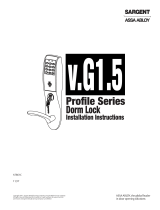
S1/S2 Replacement Controller Instructions
52-4424, 52-4425, 52-4533, 52-4537
FOR INSTALLATION ASSISTANCE CONTACT SARGENT • 1-800-810-WIRE (9473) • www.sargentlock.com
1. On the inside of the door, remove the security screw from the battery
cover on the inside escutcheon (Fig. 1).
2. Lift and remove the battery cover (Fig. 1).
This controller has been configured as a generic replacement.
The serial number MUST be changed before it can be used!
(For serial configuration, refer to Step 2 - Configure Serial Number )
NOTE: For S2 Controllers previously labeled 52-4426, use 52-4425 for the
replacement controller part number.
1 - Replace Controller
Fig. 1
6. Remove inside escutcheon assembly from door.
3a. For exit devices, continue to Step 4 (the inside lever handle does
not need to be removed in order to change the controller).
3b. For a cylindrical lock, remove the inside lever handle by inserting
the push-pin tool (provided with lock) as shown in Figure 2A.
3c. For a mortise lock, remove the inside lever handle by loosening
the lever handle set screw (Fig. 2B).
4. Remove top and bottom through-bolts from inside escutcheon.
5. Carefully separate escutcheon slightly from door and disconnect
antenna (iCLASS only), gray ribbon reader cable, green grounding wire,
motor harness, DPS harness (Fig. 2C), and hard-wired harness/PoE (if present).
Set Screw
Fig. 2B
Inside Lever
Inside of door
Push-Pin Tool
Fig. 2A
Fig. 2C

A8094B 2
12/30/12
Copyright © 2012 Sargent Manufacturing Company, an ASSA ABLOY Group company. All rights reserved.
Reproductions in whole or in part without express written permission of Sargent Manufacturing Company is prohibited.
FOR INSTALLATION ASSISTANCE CONTACT SARGENT • 1-800-810-WIRE (9473) • www.sargentlock.com
S1/S2 Replacement Controller Instructions
52-4424, 52-4425, 52-4533, 52-4537
6. Remove the four (4) Phillips screws holding the
original controller in place (Fig. 3).
Remove controller.
7. Seat the replacement controller into inside escutcheon.
Attach with the four (4) original Phillips screws.
8. Reconnect the keypad harness, ground wire, DPS
harness, motor harness, and hard-wired/PoE harness
(if present). See Figure 4.
9. Mount the inside escutcheon back on the door using
the two through-bolt screws (Fig. 4).
Reattach lever (if applicable).
10.
Install batteries and battery keeper.
Fig. 3
Fig. 4
Through-bolt
1. Place (6) “AA” batteries in the compartment, being careful to align polarity properly (Fig. 5B)
2. Replace battery keeper being careful to engage tabs at top to hold it in place. (Fig. 5A)
Fig. 5A
Fig. 5B

A8094B 3
12/30/12
Copyright © 2012 Sargent Manufacturing Company, an ASSA ABLOY Group company. All rights reserved.
Reproductions in whole or in part without express written permission of Sargent Manufacturing Company is prohibited.
FOR INSTALLATION ASSISTANCE CONTACT SARGENT • 1-800-810-WIRE (9473) • www.sargentlock.com
S1/S2 Replacement Controller Instructions
52-4424, 52-4425, 52-4533, 52-4537
1. Using Lock Configuration Tool (LCT), connect to the
new controller.
2. From the main drop down (Fig. 6A), select “Configure
Serial Number”.
3. Click ‘Go’.
2 - Configure Serial Number
6. Click “Apply Serial Number (S/N)”.
7. Configure lock as usual.
8. Replace battery cover and install security screw.
Fig. 6B Configure Serial Number
Fig. 6A
4. Select the correct reader/human interface.
5. Select the correct lock body.
NOTE: Please confirm last five (5) digits of serial number
match previous controller.

A8094B 4
12/30/12
Copyright © 2012 Sargent Manufacturing Company, an ASSA ABLOY Group company. All rights reserved.
Reproductions in whole or in part without express written permission of Sargent Manufacturing Company is prohibited.
FOR INSTALLATION ASSISTANCE CONTACT SARGENT • 1-800-810-WIRE (9473) • www.sargentlock.com
S1/S2 Replacement Controller Instructions
52-4424, 52-4425, 52-4533, 52-4537
1. Attach battery cover to inside escutcheon
making sure to line up tabs with retaining
slots in battery cover.
2. Secure with the security screw and tool
(P/N 01-0297) (Fig. 7A).
Security Tool
Retaining
slots
Tabs
Fig. 7A
3 - Replace Battery Cover
/