Sargent v.G1.5 Installation Instructions Manual
- Type
- Installation Instructions Manual

A7856C
10/16
Copyright 2016, Sargent Manufacturing Company, an ASSA ABLOY Group company.
All rights reserved. Reproduction in whole or in part without the express written
permission of Sargent Manufacturing Company is prohibited.
Profile
& LK Exit Device
Installation Instructions
v.G1.5


1-800-810-WIRE • www.sargentlock.com • A7856C
Copyright © 2016, Sargent Manufacturing Company, an ASSA ABLOY Group company. All rights reserved.
Reproductions in whole or in part without express written permission of Sargent Manufacturing Company is prohibited.
10/31/16
Table of Contents
Warning ............................................................................ 3
General Description
.......................................................... 4
Specifications
................................................................... 4
Features
............................................................................ 4
Parts Breakdown
8877/8878 x ET x Profile Series Rim Exit Device
............. 5
8977/8978 x ET x Profile Series Mortise Exit Device
....... 7
Installation Instructions: Rim 8877/8878
........................ 9
Installation Instructions: Mortise 8977/8978
................ 15
RF Technology Lock
........................................................ 21
Wiring Options
................................................................ 22
Operational Check
.......................................................... 27
10
1
2
3
4
5
6
7
8
9
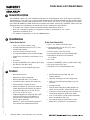
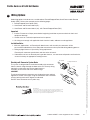
This device complies with Part 15 of the FCC Rules. Operation is subject to the following two conditions: (1) this
device may not cause harmful interference, and (2) this device must accept any interference received, including
interference that may cause undesired operation.
Note: This equipment has been tested and found to comply with the limits for a Class B digital device, pursuant to
Part 15 of the FCC Rules. These limits are designed to provide reasonable protection against harmful interference
in a residential installation.
This equipment generates, uses and can radiate radio frequency energy and if not installed and used in accordance
with the instructions, may cause harmful interference to radio communications. However, there is no guarantee that
the interference will not occur in a particular installation. If this equipment does cause harmful interference to radio
or television reception, which can be determined by turning the equipment off and on, the user is encouraged to try
to correct the interference by one or more of the following measures:
• Reorient or relocate the receiving antenna
• Increase the separation between the equipment and receiver
• Connect the equipment into an outlet on a circuit different from that to which the receiver is connected
• Consult the dealer or an experienced TV technician for help
This Class B digital apparatus complies with Canadian ICES-003.
Cet appareil numérique de la classe B est conforme avec la norme NMB-003 du Canada.
To comply with “Fire Listed” doors, the batteries must be replaced with alkaline batteries only.
Do not install batteries if controller is powered by external power supply.
Warning SARGENT Mfg. Co. locksets utilizing a door position switch (DPS)
are not rated for, or intended for use in life safety applications.
!
!
Warning
Changes or modifications to this unit not expressly approved by the party
responsible for compliance could void the user’s authority to operate the equipment.
1

4 1-800-810-WIRE • www.sargentlock.com • A7856C
Profile Series v.G1.5 Rim Exit Device
Copyright © 2016, Sargent Manufacturing Company, an ASSA ABLOY Group company. All rights reserved.
Reproductions in whole or in part without express written permission of Sargent Manufacturing Company is prohibited.
10/31/16
Specifications
3
Profile Series Rim Exit
• Latch – 3/4” throw, stainless steel
• Outside motor driven Exit Trim (“ET”) lever
controlled by keypad
• Push bar retracts latch from inside
• Fire stop provided on all lever handle designs
• Profile Series exit devices furnished for 1-3/4”
doors
• UL Listed
• Accepts all SARGENT rim cylinders (8877 only)
• Key retracts latch (8877 only)
• Available in ET lever handle designs only
Profile Series Mortise Exit
• Latch – 3/4” throw, anti-friction, brass
• Outside motor driven Exit Trim (“ET”) lever
controlled by keypad
• Push bar retracts latch from inside
• Fire stop provided on all lever handle designs
• Profile Series exit devices furnished for
1-3/4” doors
• UL Listed
• Accepts all SARGENT mortise cylinders (8977 only)
• Key retracts latch (8977 only)
• Available in ET lever handle designs only
General Description
2
Features
4
The SARGENT Profile v.G1.5 Rim and Mortise Exit Devices are designed for areas which require stand-alone
authorized entry. They consist of a self-contained microprocessor-controlled keypad with non-volatile memory.
The keypad holds a total of 100(LK)/2000 (G1-LU, G1-PK, G1-PA, G1-TU, G1-TP, G1-TA) different user codes.
User codes 01 and 02 are utilized for Master and Supervisory Codes, respectively. SARGENT mortise locks are
designed with quality components to provide high security, performance and durability.
• The Profile v.G1.5 Series provides enhanced software and hardware features.
• New v.G1.5 controllers replace v.G1 controllers. Product is still ordered as “G1-” prefix.
Controllers are labeled “G1.5”.
• This product is operated by six (6) “AA” alkaline batteries.
• RF Fob and Proximity Card, Tag, and
Fob are optional
• Operates utilizing any one to six digit code.
• Digits may be repeated and codes may start
with zero
• Cylinder override
• Entry of three wrong User Codes disables all
codes for ten seconds. Yellow LED on solid
• Piezo horn can be heard with each keystroke or
turned off by Master or Supervisory Code
• Last 15 transactions can be output to portable
print via infrared link (LK Only)
• Last 2000 (Except LK) transactions can be
output to PC via SofLink™ Plus Software
• Non-volatile memory
• Motor driven, battery operated
• Battery operated with 6 “AA” Alkaline
• Low battery alert–4 chirps after code entry
• External remote “request to enter”
• Master, Emergency or Supervisory code will
unlock door when low battery has expired
• 100 (LK) or 2000 (G1-LU, G1-PK, G1-PA,
G1-TU, G1-TP, G1-TA) users
• Programming done at keypad or with a DTD
(Data Transfer Device) using SoloPlus™
software and a Laptop /PC (G1-TA and
G1-TP require software)
SoloPlus™ works with PalmPilot; SofLink™
Plus software not supported with DTD.

1-800-810-WIRE • www.sargentlock.com • A7856C 5
Profile Series v.G1.5 Rim Exit Device
Copyright © 2016, Sargent Manufacturing Company, an ASSA ABLOY Group company. All rights reserved.
Reproductions in whole or in part without express written permission of Sargent Manufacturing Company is prohibited.
10/31/16
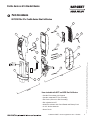
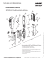
5
Parts Breakdown
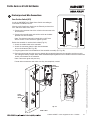
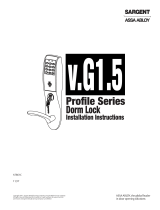
Items included with 8877 and 8878 Rim Exit Device:
• Outside Escutcheon with Keypad
• Outside motorized ET Trim Assembly
• Exit Device (Chassis & Rail Assembly)
• Rim cylinder for 8877
• Inside Escutcheon with Circuit Board and Battery Pack
• 6 “AA” alkaline batteries
• Screw Packs
1
6
2
3
5
12
11
14
15
9
11
12
8
7
4
13
10
16
17
Outside
Inside
8877/8878 x ET x Profile Series Rim Exit Device

6 1-800-810-WIRE • www.sargentlock.com • A7856C
Profile Series v.G1.5 Rim Exit Device
Copyright © 2016, Sargent Manufacturing Company, an ASSA ABLOY Group company. All rights reserved.
Reproductions in whole or in part without express written permission of Sargent Manufacturing Company is prohibited.
10/31/16
1 52-2839 Outside Escutcheon (Prox Only) Assembly (G1-PA, G1-TA) 1
52-2474 Outside Escutcheon (Key Pad Only) Assembly (LK)
52-2838 Outside Escutcheon (Key Pad/Prox) Assembly (G1-LU, G1-PK, G1-TU, G1-TP)
52-2704 Key Pad and Proximity Assembly (G1-LU, G1-PK, G1-TU, G1-TP) 1
52-2432 Key Pad/Proximity Bezel Assembly w/ Harness (LK)
52-2706 Proximity Only Assembly (G1-PA, G1-TA) 1
68-1397 Outside Escutcheon Housing Only 1
52-0176 Outside Escutcheon End Cap 1
2 52-2460 Inside Escutcheon Assembly with 100 User Controller (LK) 1
52-2833 Inside Escutcheon Assembly with 2000 User Controller (G1-LU)
52-2834 Inside Escutcheon Assembly with Prox/Key Pad Controller (G1-PA, G1-PK)
52-2836 Inside Escutcheon Assembly (Key Pad Only) with RF Technology Controller (G1-TU)
52-2835 Inside Escutcheon Assembly (Key Pad/Prox or Prox Only) with RF Technology Controller
(G1-TA, G1-TP)
68-1396 Inside Escutcheon Housing Only 1
52-0175 Inside Escutcheon End Cap Only 1
52-2441 100 User Controller Assembly (LK) 1
52-2783 2000 User Controller Assembly (G1-LU)
52-2784 2000 User Controller Assembly (G1-PA, G1-PK)
52-2786
2000 User (Key Pad/Prox or Prox Only) Controller Assembly w/ RF Technology (G1-TA, G1-TP)
52-2785 2000 User (Key Pad Only) Controller Assembly w/ RF Technology (G1-TU)
3 52-0170 Battery Cover 1
52-2309 Battery Cover – RF Technology (G1-TU,G1-TP, G1-TA)
4 01-1212 Security Screw 1
5 01-0297 Security Tool 1
6 52-0033 Fire Stop Plate 1
7 01-1500 Fire Stop Screws #8 x 1/2” Type “AB” Phillips Pan Head Self Tap 2
8 52-0253 Battery Keeper 1
52-0344 Battery Keeper – RF Technology (G1-TU, G1-TP, G1-TA)
9
Consult Factory
Motorized ET Lever Trim (with Key and Cylinder) 1
10
Consult Factory
Motor and Harness Assembly 1
11 01-4451 ET Through-bolts 2
12 77-0685 Escutcheon Through-bolts 2
13 68-4261 Center Case Assembly LHRB & RHRB (Std.)
68-4263 Center Case Assembly LHRB (12-) & RHRB (12-) 2
14 68-0406 Chassis Cover 1
15 97-0052 Chassis Cover Screws 4
52-2425 Screw Pack (Includes item numbers 5,6,7,15) 1
16 52-0263 Gasket, ET 1
17 68-1400 Gasket, Escutcheon 1
01-0803 Battery Alkaline (“AA” Cell) (Not Shown) 6
ITEM PART NO.
DESCRIPTION REQ’D
Parts Breakdown 8877/8878 x ET x Profile Series Rim Exit Device (Continued)

1-800-810-WIRE • www.sargentlock.com • A7856C 7
Copyright © 2016 Sargent Manufacturing Company, an ASSA ABLOY Group company. All rights reserved.
Reproductions in whole or in part without express written permission of Sargent Manufacturing Company is prohibited.
Profile Series v.G1.5 Mortise Exit Device
10/31/16
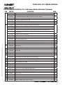
Parts Breakdown (continued)
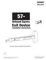
Items included with 8977 and 8978 Mortise Exit Device:
• Outside Escutcheon with Keypad
• Outside Motorized ET Trim Assembly
• Exit Device (Chassis, Rail Assembly and Mortise Lock)
• Mortise Cylinder for 8977
• Inside Escutcheon with Circuit Board and Battery Pack
• 6 “AA” alkaline batteries
• Screw Packs
1
6
2
8
3
5
4
16
17
11
12
13
10
7
14
15
19
Outside
Inside
18
8977/8978 x ET x Profile Series Mortise Exit Device

8 1-800-810-WIRE • www.sargentlock.com • A7856C
Copyright © 2016 Sargent Manufacturing Company, an ASSA ABLOY Group company. All rights reserved.
Reproductions in whole or in part without express written permission of Sargent Manufacturing Company is prohibited.
Profile Series v.G1.5 Mortise Exit Device
10/31/16
1 52-2839 Outside Escutcheon (Prox Only) Assembly (G1-PA, G1-TA) 1
52-2838 Outside Escutcheon (Key Pad/Prox) Assembly (G1-LU, G1-PK, G1-TU, G1-TP)
52-2704 Key Pad and Proximity Assembly (G1-LU, G1-PK, G1-TU, G1-TP) 1
52-2432 Key Pad/Proximity Bezel Assembly w/ Harness (LK)
52-2706 Proximity Assembly (G1-PA, G1-TA) 1
68-1397 Outside Escutcheon Housing Only 1
52-0176 Outside Escutcheon End Cap Only 1
2 52-2460 Inside Escutcheon Assembly with 100 User Controller (LK) 1
52-2833 Inside Escutcheon Assembly with 2000 User Controller (G1-LU)
52-2834 Inside Escutcheon Assembly with Prox/Key Pad Controller (G1-PA, G1-PK)
52-2836 Inside Escutcheon Assembly (Key Pad Only) with RF Technology Controller (G1-TU)
52-2835 Inside Escutcheon Assembly (Key Pad/Prox or Prox Only) with RF Technology Controller
(G1-TA, G1-TP)
68-1396 Inside Escutcheon Housing Only 1
52-0175 Inside Escutcheon End Cap Only 1
52-2441 Enclosure Assembly (LK) 1
52-2783 Enclosure Assembly (G1-LU) 1
52-2784 Key Pad/Prox or Prox Only Controller Assembly (G1-PA, G1-PK) 1
52-2786
2000 User (Key Pad/Prox or Prox Only) Controller Assembly w/ RF Technology (G1-TA, G1-TP)
1
52-2785 2000 User (Key Pad Only) Controller Assembly w/ RF Technology (G1-TU) 1
3 52-0170 Battery Cover 1
52-2309 Battery Cover – RF Technology (G1-TU,G1-TP, G1-TA) 1
4 01-1212 Security Screw 1
5 01-0297 Security Tool 1
6 52-0033 Fire Stop Plate 1
7 01-1500 Fire Stop Screws #8 x 1/2” Type “AB” Phillips Pan Head Self Tap 2
8 52-0253 Battery Keeper 1
52-0344 Battery Keeper – RF Technology (G1-TU, G1-TP, G1-TA)
9 52-2425 Screw Pack (Includes item numbers 5, 6, 7, 12, 13) (not shown) 1
10
Consult Factory
Motorized ET Lever Trim 1
11
Consult Factory
Motor and Harness Assembly 1
12 01-4451 ET Through-bolts 2
13 77-0685 Escutcheon Through-bolts 2
14 68-2172 Center Case Assembly LHRB (Standard and 12-) 1
68-2173 Center Case Assembly RHRB (Standard and 12-) 1
15 99-2401 Mortise Lock LHRB 1
99-2402 Mortise Lock RHRB 1
16 68-0407 Chassis Cover 1
17 97-0052 Chassis Cover Screws 4
18 68-1400 Chassis Gasket 1
19 52-0263 ET gasket 1
01-0803 Batteries - Alkaline (“AA” Cell) (not shown) 6
ITEM PART NO.
DESCRIPTION REQ’D
Parts Breakdown 8977/8978 x ET x Profile Series Mortise Exit Device (Continued)

1-800-810-WIRE • www.sargentlock.com • A7856C 9
Profile Series v.G1.5 Rim Exit Device
Copyright © 2016, Sargent Manufacturing Company, an ASSA ABLOY Group company. All rights reserved.
Reproductions in whole or in part without express written permission of Sargent Manufacturing Company is prohibited.
10/31/16
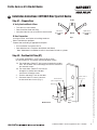
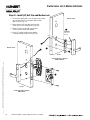
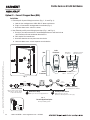
For exterior applications, use ET gasket (P/N 52-0263)
to seal between ET escutcheon and outside door surface.
1A. For wood doors: Route ET wire harness through the cylinder
hole, out the other side, and through the wire run channel to
the controller cutout.
1B. For metal doors: Route ET wire harness
through the cylinder hole and door
and out the controller cutout.
2. Position and hold ET trim on the door.
3. Connector from ET harness connects
to connector from chassis (Fig. 2)
6
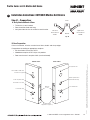
Installation Instructions: 8877/8878 Rim Type Exit Device
Step #2 – Position Exit Trim (ET)
Step #1 – Prepare Door
A. Verify Hand and Bevel of Door
• This device is non-handed.
• Door should be fitted and hung.
• Verify box label for size of exit device and function.
Inside
Outside
Left Hand
Reverse Bevel
LHRB
Right Hand
Reverse Bevel
RHRB
Fig. 1
B. Door Preparation
If using a mullion, install prior to installing hardware.
Doors should be pre-prepped.
Prepare door according to appropriate template:
• Exit installation instructions A6770
• Door Manufacturer’s Template 4640 (Metal and Wood)
Note: Wood door has additional cutout if installation includes a cylinder.
Outside of Door
ET Wire Harness
(from motor)
Fig. 2
Exit trim
Exit trim Gasket
(Exterior Applications)

10 1-800-810-WIRE • www.sargentlock.com • A7856C
Profile Series v.G1.5 Rim Exit Device
Copyright © 2016, Sargent Manufacturing Company, an ASSA ABLOY Group company. All rights reserved.
Reproductions in whole or in part without express written permission of Sargent Manufacturing Company is prohibited.
10/31/16
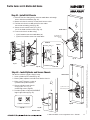
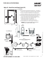
Step #3 – Mount Exit Device Chassis (Inside Trim)
1. Route ET harness along track cutout for wood doors and
through access hole for metal doors.
2. Position exit chassis carefully.
Do not pinch the wire harness.
3. Engage ET spindle in hub of exit device chassis.
4. Secure the exit chassis with through-bolts
to the ET trim using (2) 1/4 -20 x 2-3/8”
flat head machine screws.
Correct
Incorrect
Fig. 4C
Step #4 – Install Cylinder and Secure Chassis
For devices without cylinder, skip this step.
1. Insert cylinder into ET control (Fig. 4A).
2. Mate cylinder tailpiece into hub of exit device chassis.
3. Make sure ET harness is clear of cylinder and cylinder tailpiece.
4. Secure cylinder to exit chassis using (2) #12-24 x 1-7/8”
connecting screws (Fig 4B).
5. Fasten exit chassis to door using:
• (4) #10 wood screws for wood doors (or)
• (4) #10-24 machine screws for metal doors.
6. Position cylinder so that the SARGENT
logo is right-side up (Fig. 4C).
Inside of Door
Fig. 3
(2) 1/4 x 2-3/8” Flathead
Machine Screws
Exit Chassis
ET Motor
Harness
(4) #10 Wood or
#10-24 Machine
Screws
(2) #12-24 x 1-7/8”
Flat Head Screws
(Connecting Cylinder)
Inside of Door
Outside of Door
Inside of Door
Fig. 4B
Fig. 4A
Fig. 4B

1-800-810-WIRE • www.sargentlock.com • A7856C 11
Profile Series v.G1.5 Rim Exit Device
Copyright © 2016, Sargent Manufacturing Company, an ASSA ABLOY Group company. All rights reserved.
Reproductions in whole or in part without express written permission of Sargent Manufacturing Company is prohibited.
10/31/16
B. Weather Conduit (P/N 52-2847)
Install weather conduit on NON FIRE-RATED
exterior doors only.
1. Carefully insert the weather conduit
into the ribbon cable hole on
the inside of the door (Fig 5B).
2. Place the O-ring around the
weather conduit on the outside
and up against the door (Fig. 5C).
Step #5 – Exterior Door Options
Outside of Door
A. Fire Stop Plate (P/N 52-0033)
Fire-rated doors require a fire stop plate on the
outside of the door (Fig.5A).
1. Drill (2) 1/8" x 1-1/4" deep holes in the door if not
already present.
Refer to template for fire-stop prep locations.
2. Attach with flap up and out using (2) #8 x 1/2”
self-tapping screws for wood
and metal doors.
Fig. 5A
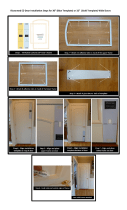
Step #6 – Gasket Installation (for Exterior Doors)
For exterior applications, use a gasket between
escutcheon and outside door surface:
1. Carefully remove the backing from the gasket.
2. Apply gasket to escutcheon carefully.
a. Starting in one place, press the adhesive side
of the gasket firmly against the escutcheon.
b. Work around the escutcheon, pressing the sticky side
of the gasket firmly against the escutcheon edge.
c. The gasket should be aligned so that all edges
of the escutcheon are covered.
4. Attach escutcheon to the door.
Fig. 6B
Fig. 6A
Fig.5B
Ribbon Cable Hole
Fig.5C
O-Ring
Outside of Door

12 1-800-810-WIRE • www.sargentlock.com • A7856C
Profile Series v.G1.5 Rim Exit Device
Copyright © 2016, Sargent Manufacturing Company, an ASSA ABLOY Group company. All rights reserved.
Reproductions in whole or in part without express written permission of Sargent Manufacturing Company is prohibited.
10/31/16
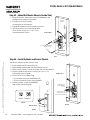
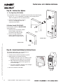
Step #7 – Install Outside Escutcheon
For 12- fire rated exit devices, feed keypad
ribbon cable/connector from outside of door
through the gasket then
fire stop plate (Fig. 7).
For non-fire 12- exit devices, feed keypad
ribbon cable/connector through gasket then
through the conduit hole in door.
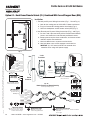
Step #8 – Connect and Position Outside Escutcheon Wires
Images shown represent installation without gasket. If gasket is necessary, refer to Step #6.
Before the controller is attached to the door:
1. Attach the reader assembly ribbon cable to the inside face of the controller assembly (side that
faces towards the door when mounted (Fig. 8B).
Note: Install ribbon cable with side marked TOP facing up. (Fig. 8A).
2. Attach the ground wire to the bottom of the controller assembly (E1, Fig. 8A).
3. Connect the exit connector to the bottom of the controller (TB1, Fig. 8B).
If Hardwiring is required, go to “Hardwire Wiring Options” on page 14.
4. Place extra wire inside door hole and/or outside escutcheon,
being careful not to pinch wires.
Connectors go on only one way.
Do not offset connectors,
and make sure they are
completely seated.
Outside of Door
Fire
Stop
Plate
Weatherseal
Gasket
Ribbon
Cable
Outside
escutcheon
Fig. 7
Outside Escutcheon
1
Reader Cable
Ground Wire
1
2
Fig. 8A
Ground
Wire
Reader Cable
P1
2
1
2
Fig. 8B
TB1
Motor
Connector
TB2
Power/Data
Connector
E3
RedBlack
TB1
3
3
3

1-800-810-WIRE • www.sargentlock.com • A7856C 13
Profile Series v.G1.5 Rim Exit Device
Copyright © 2016, Sargent Manufacturing Company, an ASSA ABLOY Group company. All rights reserved.
Reproductions in whole or in part without express written permission of Sargent Manufacturing Company is prohibited.
10/31/16
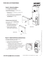
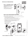
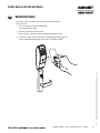
Step 9 – Install and Secure Inside Escutcheon
1. Secure the inside escutcheon using two #8-32
screws through top and bottom of the
escutcheon (Fig. 9).
Thread into outside escutcheon.
2. Straighten escutcheons and tighten securely,
being careful to avoid pinching wires.
Battery Cover
Security
Screw
Security Tool
(P/N 01-0297, Included
Battery Keeper
Fig. 9
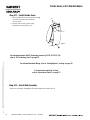
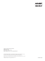
Step #10 – Install and Remove Batteries*
A. Install Batteries and Keeper
1. Place (6) “AA” batteries into the compartment, being careful to properly align polarity (Fig. 10A).
2. To install battery keeper, insert the tabs on the bottom of the keeper into the battery compartment slots
and press the keeper tightly against batteries and inserting tabs into bottom slots.
• For RF technology, use RF Technology lock information 20.
IMPORTANT: * Do not install batteries if controller is powered by external power supply.
• Test for proper operation before closing door.
B. Remove Battery Keeper
To remove the battery keeper, pull the keeper away from the batteries (Fig. 10B).
Fig. 10B
+
-
+
+
-
+
Fig. 10A
Bottom Tabs
(Battery Keeper)
Keeper Tabs
Battery Keeper
Tip Out

14 1-800-810-WIRE • www.sargentlock.com • A7856C
Profile Series v.G1.5 Rim Exit Device
Copyright © 2016, Sargent Manufacturing Company, an ASSA ABLOY Group company. All rights reserved.
Reproductions in whole or in part without express written permission of Sargent Manufacturing Company is prohibited.
10/31/16
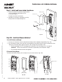
Attach rail assembly according to Exit Installation Instructions A6770.
Step #12 – Install Rail Assembly
For information about the RF Technology versions (G1-TU, G1-TP, G1-TA),
refer to “RF Technology Lock” on page 21.
For information about Wiring, refer to “Wiring Options” starting on page 22.
For information about the Testing,
refer to “Operational Check” on page 27.
Tabs
Fig. 11
Retaining Slots
Step #11 – Install Inside Cover
1. Attach inside cover to escutcheon making
sure to line up tabs with retaining
slots in cover.
2. Secure with security screw using
provided security tool Fig. 11).

1-800-810-WIRE • www.sargentlock.com • A7856C 15
Copyright © 2016 Sargent Manufacturing Company, an ASSA ABLOY Group company. All rights reserved.
Reproductions in whole or in part without express written permission of Sargent Manufacturing Company is prohibited.
Profile Series v.G1.5 Mortise Exit Device
10/31/16
7
Installation Instructions: 8977/8978 Mortise Exit Device
Inside
Outside
Left Hand
Reverse Bevel
“LHRB”
Right Hand
Reverse Bevel
“RHRB”
Fig. 1A
B. Door Preparation
Prior to installation, all holes must be free of burrs, debris and sharp edges.
Prepare door according to appropriate template:
• Exit installation instructions A6770
• Wood door template A7457 ships with product.
• Door manufacturer’s template 4641 (metal and wood)
Through-bolt Hole
Outside Cylinder Hole
(76 and 78 Functions)
Lever Handle Hole
Pre-drilled and/or
Tapped Holes (2 places)
Mortised
Pocket
Hole for Ribbon Cable from
Controller to Keypad
Inside of Cylinder Hole
Thumb Turn Lever Hole
Lever Handle Hole
Inside of DoorOutside of Door
Step #1 – Prepare Door
A. Verify Hand and Bevel of Door
• This device is non-handed.
• Door should be fitted and hung.
• Verify box label for size of exit device and function.

16 1-800-810-WIRE • www.sargentlock.com • A7856C
Copyright © 2016 Sargent Manufacturing Company, an ASSA ABLOY Group company. All rights reserved.
Reproductions in whole or in part without express written permission of Sargent Manufacturing Company is prohibited.
Profile Series v.G1.5 Mortise Exit Device
10/31/16
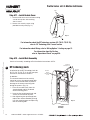
1. For exterior applications, use ET gasket (52-0263)
to seal between ET escutcheon and outside
door surface (Fig. 2A).
2. Slide mortise lock into door and securely
fasten with (2) flat head screws (Fig. 2B).
3. Route ET harness through square wire
cutout and out other side of door.
4. Place ET control on door with spindle
inserted through mortise lock (Fig. 2A).
Step #2 - Install (ET) Exit Trim and Mortise Lock
Fig. 2B
Outside of Door
Showing Wood Door Template
With Cylinder
2
Fig. 2A
Showing Wood Door Template
Without Cylinder
ET gasket
(part number
52-0263)
Outside of Door
1
3
4

1-800-810-WIRE • www.sargentlock.com • A7856C 17
Copyright © 2016 Sargent Manufacturing Company, an ASSA ABLOY Group company. All rights reserved.
Reproductions in whole or in part without express written permission of Sargent Manufacturing Company is prohibited.
Profile Series v.G1.5 Mortise Exit Device
10/31/16
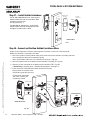
Step #3 - Install Exit Chassis
Fig. 3A
Fig. 3C
Latchbolt
Lever arm
Chassis
Lever
1. Route ET harness along track cutout for wood doors or through
access hole for metal doors (Fig. 3A).
2. Mount exit chassis carefully. Do not pinch harness wires.
3. Position exit chassis on door with lever arm under
rear section of mortise lock (Fig. 3B).
4. Secure chassis and ET with (2) 1/4-20 x
2-3/8” flat head machine screws (Fig. 3A).
4. Fasten exit chassis to door using:
• (4) #10 wood screws for wood doors (or)
• (4) #10-24 machine screws for metal doors.
Correct
Incorrect
Fig. 4C
Step #4 – Install Cylinder and Secure Chassis
For devices without cylinder, skip this step.
1. Insert cylinder into ET control (Fig. 4A).
2. Mate cylinder tailpiece into hub of exit device chassis.
3. Make sure ET harness is clear of
cylinder and cylinder tailpiece.
4. Secure cylinder to exit chassis
using (2) #12-24 x 1-7/8”
connecting screws (Fig 4B).
5. Position cylinder so that the SARGENT
logo is right-side up (Fig. 4C).
Outside of Door
Inside of Door
Fig. 4B
Fig. 4A
Inside of Door
Fig. 4B
Inside of Door
Fig. 3B
(4) #10 Wood or
#10-24 Machine
Screws
(2) #12-24 x 1-7/8”
Connecting Screws

18 1-800-810-WIRE • www.sargentlock.com • A7856C
Copyright © 2016 Sargent Manufacturing Company, an ASSA ABLOY Group company. All rights reserved.
Reproductions in whole or in part without express written permission of Sargent Manufacturing Company is prohibited.
Profile Series v.G1.5 Mortise Exit Device
10/31/16
Step #5 – Exterior Door Options
A. Fire Stop Plate (P/N 52-0033)
Fire-rated doors require a fire stop plate on the outside of the door (Fig.5A).
1. Drill (2) 1/8" x 1-1/4" deep holes in the door if not already present.
Refer to template for fire-stop prep locations.
2. Attach with flap up and out using (2)
#8 x 1/2” self-tapping screws for
wood and metal doors.
Outside of Door
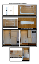
Step #6 – Gasket Installation (for Exterior Doors)
For exterior applications, use a gasket between
escutcheon and outside door surface:
1. Carefully remove the backing from the gasket.
2. Apply gasket to escutcheon carefully.
a. Starting in one place, press the adhesive side
of the gasket firmly against the escutcheon.
b. Work around the escutcheon, pressing the
sticky side of the gasket firmly against the
escutcheon edge.
c. The gasket should be aligned so that all edges
of the escutcheon are covered.
4. Attach escutcheon to the door.
Fig. 6B
Fig. 6A
Fig. 5A
B. Weather Conduit (P/N 52-2847)
Install weather conduit on NON FIRE-RATED
exterior doors only.
1. Carefully insert the weather conduit
into the ribbon cable hole on
the inside of the door (Fig 5B).
2. Place the O-ring around the
weather conduit on the outside
and up against the door (Fig. 5C).
Fig.5B
Ribbon Cable Hole
Fig.5C
O-Ring
Outside of Door

1-800-810-WIRE • www.sargentlock.com • A7856C 19
Copyright © 2016 Sargent Manufacturing Company, an ASSA ABLOY Group company. All rights reserved.
Reproductions in whole or in part without express written permission of Sargent Manufacturing Company is prohibited.
Profile Series v.G1.5 Mortise Exit Device
10/31/16
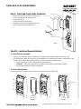
Step #7 – Install Outside Escutcheon
For 12-fire rated exit devices, feed keypad
ribbon cable/connector from outside of
door through the gasket then fire stop
plate (Fig. 7).
For non fire-12-exit devices, feed keypad
ribbon cable/connector through gasket
then through the conduit hole in door.
Step #8 – Connect and Position Outside Escutcheon Wires
Images shown represent installation without gasket. If gasket is necessary, refer to Step #6.
Before the controller is attached to the door:
1. Attach the reader assembly ribbon cable to the inside face of the controller assembly (side that
faces towards the door when mounted (Fig. 8B).
Note: Install ribbon cable with side marked TOP facing up. (Fig. 8A).
2. Attach the ground wire to the bottom of the controller assembly (E1, Fig. 8A).
3. Connect the exit connector to the bottom of the controller (TB1, Fig. 8B).
If Hardwiring is required, go to “Hardwire Wiring Options” on page 14.
4. Place extra wire inside door hole and/or outside escutcheon,
being careful not to pinch wires.
Connectors go on only one way.
Do not offset connectors,
and make sure they are
completely seated.
Outside of Door
Fire
Stop
Plate
Weatherseal
Gasket
Ribbon
Cable
Outside
escutcheon
Fig. 7
Outside Escutcheon
1
Reader Cable
Ground Wire
1
2
Fig. 8A
Ground
Wire
Reader Cable
P1
2
1
2
Fig. 8B
TB1
Motor
Connector
TB2
Power/Data
Connector
E3
RedBlack
TB1
3
3

20 1-800-810-WIRE • www.sargentlock.com • A7856C
Copyright © 2016 Sargent Manufacturing Company, an ASSA ABLOY Group company. All rights reserved.
Reproductions in whole or in part without express written permission of Sargent Manufacturing Company is prohibited.
Profile Series v.G1.5 Mortise Exit Device
10/31/16
Step 9 – Install and Secure Inside Escutcheon
1. Secure the inside escutcheon using two #8-32
screws through top and bottom of the
escutcheon (Fig. 9).
Thread into outside escutcheon.
2. Straighten escutcheons and tighten securely,
being careful to avoid pinching wires.
Fig. 9A
Battery Cover
Security
Screw
Security Tool
(P/N 01-0297, Included
Battery Keeper
Step #10 – Install and Remove Batteries*
A. Install Batteries and Keeper
1. Place (6) “AA” batteries into the compartment, being careful to properly align polarity (Fig. 10A).
2. To install battery keeper, insert the tabs on the bottom of the keeper into the battery compartment slots
and press the keeper tightly against batteries and inserting tabs into bottom slots.
• For RF technology, use RF Technology lock information “RF Technology Lock” on page 20.
IMPORTANT: * Do not install batteries if controller is powered by external power supply.
• Test for proper operation before closing door.
B. Remove Battery Keeper
To remove the battery keeper, pull the keeper away from the batteries (Fig. 10B).
Fig. 10B
+
-
+
+
-
+
Fig. 10A
Bottom Tabs
(Battery Keeper)
Keeper Tabs
Battery Keeper
Tip Out
Page is loading ...
Page is loading ...
Page is loading ...
Page is loading ...
Page is loading ...
Page is loading ...
Page is loading ...
Page is loading ...
-
 1
1
-
 2
2
-
 3
3
-
 4
4
-
 5
5
-
 6
6
-
 7
7
-
 8
8
-
 9
9
-
 10
10
-
 11
11
-
 12
12
-
 13
13
-
 14
14
-
 15
15
-
 16
16
-
 17
17
-
 18
18
-
 19
19
-
 20
20
-
 21
21
-
 22
22
-
 23
23
-
 24
24
-
 25
25
-
 26
26
-
 27
27
-
 28
28


Sargent v.G1.5 Installation Instructions Manual
- Type
- Installation Instructions Manual
Ask a question and I''ll find the answer in the document
Finding information in a document is now easier with AI
Related papers
-
 Sargent Passport 1000 PG Installation Instructions Manual
-
 Sargent P2 PASSPORT 1000 Specification
-
 Sargent 1431 series Installation Instructions Manual
-
 Sargent Profile Series Installation Instructions Manual
-
Assa Abloy U4A-SCYPROX3 User manual
-
 Sargent 57 Series Delayed Egress Exit Device User manual
-
 Sargent 351EHT Operating instructions
-
-
 Sargent PASSPORT 1000 Exit Device Installation Instructions Manual
-


Other documents
-
Yale All-in-One Owner's manual
-
-
-
 EZ-Door EZD-FR-30 Operating instructions
-
 EZ-Door EZD-FR-28 Installation guide
-
-
-
Alarm Lock LEKTROLOK 104 Installation Template
-
-

